318is with Rotrex C30-94 Supercharger

Discuss general engine, turbo and supercharger conversions in this section

Moderator: martauto

GeoffBob
Forced Induction Specialist
Posts: 1843
Joined: Tue Apr 28, 2009 11:00 pm

Thu May 14, 2009 7:38 pm

I received a PM from Appletree asking me to do the calculations necessary to plot the loadline for a Rotrex C30-94 supercharger fitted to a 318is.

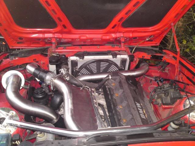
I present the results here for those interested in undertaking this (or a similar) conversion.

The first task is to calculate the pressure to which the Rotrex will boost the plenum chamber (at wide open throttle or WOT) for any given value of mass-air-flow through the engine. From the ideal gas law, and the fact that an engine inducts a constant volume (not mass) of air on each intake stroke, it can be shown that:

Image

Where:
  • Pm is the manifold absolute pressure or MAP (in pascals),
    dma/dt is the air flow through the engine (in kg/second)
    R is the universal gas constant (8.3144 Joule/kelvin.mol),
    Tm is the temperature of the air inducted into the engine (in kelvins),
    F is the mass-ratio of fuel to air (typically around 1/15 to 1/12),
    Vd is the displacement of the engine (in cubic metres),
    N is the rotational speed of the crank (in rotations/second),
    na is the molar mass of air (0.029 kg/mol), and

    Image

    is the volumetric efficiency of the engine (as a function of N).
This equation is a reasonable approximation to a 16v four cylinder engine with ev=1 at ~4000 RPM. Most importantly, it indicates that ev drops markedly above 7000RPM, which is a characteristic of most engines.

Unfortunately, due to the adiabatic heating of the air passing through the supercharger (this is what happens when you compress a gas) the temperature Tm of the air being inducted into the engine is a function of pressure. Assuming an intercooler is included to cool the air coming out of the supercharger then, from first principles it can be shown that:

Image

Where:
  • Ta is the ambient air temperature, assumed to be 293 kelvin (20'C) in this case,
    eic is the efficiency of the intercooler (typically around 0.7 for a standard unit),
    P2 is the absolute pressure of the air at the Rotrex outlet (in pascals), and
    P1 is the absolute pressure of the air at the Rotrex inlet, assumed 100kPa (at sea level) in this case.
The power of 0.286 comes in as a result of the ratio of the specific heats of air at constant pressure and constant volume, and is not for discussion here. The pressure ratio of the compressor is simply P2/P1, and is a commonly used indicator of by how much the compressor multiplies the ambient pressure.

Putting these three equations together we get:

Image

Where dP is the pressure drop across the intercooler. I'll assume 7kpa in this case (1.0 psi), which will suffice for this analysis.

Now, we use this equation to determine P2 (the pressure at the supercharger outlet). Problem is, P2 features on both sides of the equation and it cannot be rearranged to solve for P2 uniquely. This is because it is a transcendental equation. In order to solve it I had to write an iterative routine in MATLAB. Bummer, you can't use a simple calculator, sorry!

The graph below shows a number of blue lines plotted on top of the Rotrex C30-94 compressor map. Each blue line is a solution to the above equation as a function of airflow (in kg/s) through the engine at a specific engine speed, where the engine speed relates to the compressor speed by the ratio of the pulley wheel diameters, and the internal gearing of the supercharger. A point is marked on the graph (in red) where each blue engine line intersects a black compressor line of the same RPM value. Joining these points establishes the loadline (in red) that defines the operation of this engine with the Rotrex C30-94 supercharger.

In this case a 140mm diameter pulley is assumed fitted to the crank, and a 100mm pulley fitted to the Rotrex. Thus, the supercharger pulley spins 1.4 times faster than the crank). This is exactly what Appletree has on his 318i at present.

Image

What the above graph tells us is that, below a compressor speed of 65000RPM (~4900 engine RPM) the loadline is to the left of the compressor surge line. Thus, below 4900RPM engine speed, the air flow around the compressor blades is turbulent and will eventually fatigue the compressor blades to destruction. This turbulence comes about as a result of the fact that the airflow across the blades is too slow to sustain the pressure ratio (P2/P1) demanded in this area of the graph.

This problem typically occurs when the selected supercharger is too large for the fitted application. That is to say, it is intended to flow a greater mass of air at these lower pressures, as would be the case on a larger capacity engine. Ideally, the plotted loadline should be located further to the right of the compressor map, not only to keep the compressor from surging, but so that the loadline passes through the most efficient operating area of the supercharger.

We can calculate the theoretical power output of the engine using the following equation:

Image

Where:
  • W is the work performed by the engine (in Joules), and
    bsfc is the weight of fuel required to liberate 1Joule of mechanical energy.
For most pump petrol (regardless of octane rating) this is roughly 8.333E-8 kg/Joule, but seems to be getting progressively worse as oil reserves run dry. Note, the octane rating of your fuel is an indication of its resistance to detonation, and says nothing about its energy content!

Thus, if W is the work done by the engine, then dW/dt is the rate at which the work is done, known to you and I as the Power Output of the engine (in Watts).

The loadline plotted on the Rotrax compressor map indicates that at 70000 compressor RPM (5300 engine RPM) around 0.14kg/s second of air flows through the supercharger at a pressure ratio of about 1.7. Taking into account the 7kPa drop over the intercooler, this equates to 63kPa (9psi) boost at the plenum chamber. Looking at the attached dyno graph, supplied by Appletree, we see a measured boost figure of 8psi at around 5200RPM, a discrepancy of only 1.0psi, but a discrepancy none the less, probably due to
  • (a) a greater pressure drop across the intercooler than assumed,
    (b) a 1psi pressure drop across the air filter and intake pipes (quite likely), or
    (c) a different atmospheric pressure than I have assumed here (I have no idea what the barometric pressure was on the day of the dyno test).
Plugging the value of 0.14kg/s into the above power equation we get a prediction of 140kW (188hp), not too far from the 185hp indicated in the dynograph (which I assume has been corrected for transmission losses). Dividing by 2.pi.N we get 257Nm (182lb/ft) or torque at 5200RPM (N=86.66). So you see, this maths mumbo-jumbo has a use after all! And you can do this calculation for as many points along the loadline as you like in order to predict the torque and power output of the engine - nifty winkeye

Image

The maximum recommended compressor speed of the Rotrex C30-94 is 100000RPM. With these pulleys this corresponds to around 7500 engine RPM, at which point the above graph indicates that the Rotrex is flowing roughly 0.25kg/s of air to the engine. This equates to an output power of 250kW, or 335hp. Unless the volumetric efficiency of the engine is markedly below that calculated, and provided the internals of the engine are sufficiently strong to handle this, I would expect that 335hp (at the flywheel) is quite likely. The trend indicated in the dynograph certainly indicates that this is possible. The trend of the graph, of course, says nothing about the condition or strength of the engine.

It is interesting to note that if one does not take into account a drop in the volumetric efficiency of the engine above ~7000RPM, the predictions will indicate abnormally high power outputs, that can not be achieved in reality!

More to come ....
Last edited by GeoffBob on Fri May 15, 2009 3:04 pm, edited 10 times in total.
jimmyspeed
E30 Zone Regular
E30 Zone Regular
Posts: 848
Joined: Sat Sep 08, 2007 11:00 pm
Location: riding a wagon wheel west

Thu May 14, 2009 7:39 pm

:mad:
appletree
E30 Zone Addict
E30 Zone Addict
Posts: 3482
Joined: Fri Jan 20, 2006 11:00 pm
Location: Retford

Thu May 14, 2009 7:51 pm

Well sofar i'am following that, looking good ( or bad as it maybe).


intresting stuff :D
Image

You should never underestimate the predictability of stupidity

M42 Supercharged 285bhp + M3 6speed box
GeoffBob
Forced Induction Specialist
Posts: 1843
Joined: Tue Apr 28, 2009 11:00 pm

Thu May 14, 2009 7:54 pm

Appletree, I'll post more later. Must get off home now. Don't worry, I have a solution waiting in the wings.
appletree
E30 Zone Addict
E30 Zone Addict
Posts: 3482
Joined: Fri Jan 20, 2006 11:00 pm
Location: Retford

Thu May 14, 2009 8:01 pm

No probs mate, like the graph its a steep learning curve :D
Image

You should never underestimate the predictability of stupidity

M42 Supercharged 285bhp + M3 6speed box
rix313
E30 Zone Team Member
Posts: 4948
Joined: Fri Oct 31, 2008 11:00 pm
Location: Silverstone
Contact:

Thu May 14, 2009 8:45 pm

Who are you mystical master mind lol!

Looking forward to the next bit.
GeoffBob
Forced Induction Specialist
Posts: 1843
Joined: Tue Apr 28, 2009 11:00 pm

Fri May 15, 2009 2:53 pm

Well, as you can all see, I have substantially modified my first post of this thread. I've corrected some mistakes I made while plotting the Rotrex loadline. Ironically, not because of an error in the maths, but because it seems I haven't yet learned to join the dots! The graph now looks exactly as it should. I've also added in an explanation of how I calculated the volumetric efficency of the engine. This is really only a best guess since I don't personally know the modified 318is engine in question. Nonetheless, it seems to work reasonably well, and should for you two if you ever need to use it.

From the explanation I have provided you should be able to gleem some clues as to how you can improve upon this setup.

In my next post I'll look at what happens when you start changing the pulley dimensions.
appletree
E30 Zone Addict
E30 Zone Addict
Posts: 3482
Joined: Fri Jan 20, 2006 11:00 pm
Location: Retford

Fri May 15, 2009 3:31 pm

Ace, think this will be a realy good thread for referance :cool:
Image

You should never underestimate the predictability of stupidity

M42 Supercharged 285bhp + M3 6speed box
User avatar
bennydotc
E30 Zone Regular
E30 Zone Regular
Posts: 271
Joined: Mon Apr 27, 2009 11:00 pm
Location: Wirral

Fri May 15, 2009 3:40 pm

Are you fitting a blower or planning a trip to Mars :eek:

Nice work :D
Ant
Retired Team Member
Retired Team Member
Posts: 10496
Joined: Tue Dec 21, 2004 11:00 pm
Location: PD+E dept :D
Contact:

Fri May 15, 2009 3:47 pm

the new plot looks far more agreeable

:thumb:
Product Development and Endurance for Delphi.

Original performance chips, original works not unlicensed copies :D Email FTW
MrWhite
E30 Zone Regular
E30 Zone Regular
Posts: 721
Joined: Fri Mar 14, 2008 11:00 pm
Location: Renfrewshire

Fri May 15, 2009 3:49 pm

Great reference thread.
Reminds me of university, and how little I understood of what was written in my lecture notes :?
rust never sleeps
appletree
E30 Zone Addict
E30 Zone Addict
Posts: 3482
Joined: Fri Jan 20, 2006 11:00 pm
Location: Retford

Fri May 15, 2009 4:08 pm

bennydotc wrote:Are you fitting a blower or planning a trip to Mars :eek:

Nice work :D
fitted it this is attempt no. 2 :mad:
Image

You should never underestimate the predictability of stupidity

M42 Supercharged 285bhp + M3 6speed box
GeoffBob
Forced Induction Specialist
Posts: 1843
Joined: Tue Apr 28, 2009 11:00 pm

Fri May 15, 2009 4:14 pm

The graph below shows the effect of reducing the size of the Rotrex supercharger pulley from 100mm, to 90mm, as suggested by Appletree. Apart from the loadline running a little closer to the surge line, it appears little different to the compressor graph presented in my first post. You might think, therefore, that it will have little effect upon engine performance. Think again!

Image

Due to the change in the ratio of the pulley diameters, the supercharger pulley now rotates 1.555 times faster than the crank pulley (compared to 1.4 on the previous setup). This means that the if the engine is revved to 7500RPM, as in the previous example, the supercharger compressor wheel will now rotate at 110000RPM, effectively 10000 RPM higher than before. Now, ignoring for the moment that this exceeds the speed limit of the supercharger, this corresponds to an airflow of roughly 0.28kg/s. Applying the above presented power equation, this amounts to 280kW (375hp) at the flywheel, and 356Nm (252 lb.ft) of torque. This substantial power and torque increase (at 7500RPM) is made possible purely by spinning the supercharger faster, which therefore provides increased airflow at all values of engine RPM.

Since, however, the compressor speed-limit is there for a reason, we will have to assume that this sort of power level is not possible with a Rotrex C30-94, even if the engine could handle it. If we assume, however, that it is possible to operate the Rotrex all the way up to its 100000RPM limit, then this corresponds to an engine speed of ~6800RPM. With this set as the engines new redline (in order not to destroy the supercharger) the Rotrex would pump (at 100000RPM) approximately 0.24kg/s of air, which is 1kg/s LESS than with the 100mm supercharger pulley!

It can therefore be stated, quite categorically, that, due to the difference in engine RPM, the Rotrex C30-94 with the 90mm pulley pumps less air at 100000RPM than the Rotrex C30-94 with the 100mm pulley. And I'll say it again, this is because the engine is displacing less volume per second at 6800RPM than at 7500RPM.

So in general, provided the speed limit of the Rotrex is adhered to, the two configurations will make more or less exactly the same power and torque, because they will flow exactly the same air. The big difference between the two, however, is that, with the 90mm pulley, the engine will achieve this power and torque proportionately sooner. In other words, the power and torque curves will rise marginally faster with respect to engine speed, but will peak at more or less exactly the same value (unless you are prepared to risk the supercharger and rev it beyond 100000RPM)

Aside from the fact that the engine will make marginally more torque and power at slightly lower engine speed, I can see no point to this configuration. The compressor will remain in surge for slightly longer (up till 5500RPM), which is detrimental to the compressor blades (in both configurations) and accounts for the dip in power and torque that is visible in the above dynograph.

If anything, the size of the supercharger pulley wheel should be increased in order to take the compressor out of surge by moving the loadline to the right. This will, however, negatively effect the power and torque of the engine.

More to come ...
Last edited by GeoffBob on Fri May 15, 2009 4:25 pm, edited 1 time in total.
GeoffBob
Forced Induction Specialist
Posts: 1843
Joined: Tue Apr 28, 2009 11:00 pm

Fri May 15, 2009 4:20 pm

Ant wrote:the new plot looks far more agreeable

:thumb:
Ah, so someone did notice! When I woke up this morning It dawned on me ('must have been thinking in my sleep again) that I had joined the dots in the wrong order. 'Can't believe I've mastered post graduate maths but I still can't put a ruler through some lines. You should see me try to tie my shoelaces...
User avatar
ShakeyC
E30 Zone Regular
E30 Zone Regular
Posts: 785
Joined: Sun Apr 29, 2007 11:00 pm

Fri May 15, 2009 4:44 pm

Somethings not quite right and can't put my finger on it yet :o: my calculations yeild similar results but im sure im missing something.
GeoffBob
Forced Induction Specialist
Posts: 1843
Joined: Tue Apr 28, 2009 11:00 pm

Fri May 15, 2009 5:27 pm

In the next graph we see the effect of reducing the crank pulley to 100mm diameter, but keeping the Supercharger pulley, from the first example, at 100mm. The supercharger pulley therefore turns at the same speed as the crank. Thus, if we set the engine redline at 7500RPM, the supercharger compressor wheel will spin at ~71000RPM. This is substantially below the supercharger redline of 100000RPM.

Image

From this graph we can see that the loadline appears to fold back on itself. This is due entirely to the drop in volumetric efficiency of the engine at high RPM. Fortunately, due to the 1:1 pulley ratio, the compressor speed will never exceed ~70000RPM, and thus we need not worry about any part of the loadline beyond this point.

More specifically, this graph indicates that the compressor is free from surge. Unfortunately, the graph also indicates a maximum airflow of around 0.17kg/s at the engine redline. This equates to roughly 170kW (228hp) of power (at the flywheel), which is quite abysmal compared to the earlier predictions (where the compressor was in surge for a large fraction of the rev range).

Unfortunately, nothing can change the fact that the Rotrex C30-94 was intended for use on a larger capacity engine, or an engine operating to much higher RPM. Both of which naturally flow more air. The simple fact that the calculated engine lines (the blue lines) lie to the left of the compressors "finger-print" are a classic indicator of this problem, and should immediately ring alarm bells with anyone pondering a similar problem.

One last post to follow .....
GeoffBob
Forced Induction Specialist
Posts: 1843
Joined: Tue Apr 28, 2009 11:00 pm

Fri May 15, 2009 6:31 pm

Appletree,

So here's my suggestion. Pack up your Rotrex C30-94 and sell it on to someone with a larger capacity engine, preferably 2.5liter and up. Then, get yourself a Rotrex C30-74. keep your 140mm crank pulley and fit a 90mm pulley to the Rotrex. Your loadline will then look as follows:

Image

Note how the loadline never crosses over into surge. Also, the C30-74 redlines at 120000RPM (8128 engine RPM). This means that if you rev your engine to 7500RPM, the compressor wheel will be spinning at just over 110000 RPM. This is ideal.

At 110000RPM the compressor will flow roughly 0.22kg/s of air. This equates to 220kW (295hp) at the flywheel, which is just shy of the 300hp you stated in your PM that you are aiming for. And most importantly, you'll achieve this without the compressor ever crossing over to the dark side! That red loadline is right up the centre, right where its supposed to be :D

The only other option that I can think of is that you keep your C30-94 , and bin your 1800cc engine in favour of large 6-pot lump. In which case I suspect that your C30-94 will deliver in the region of 400hp plus, so long as the engine can handle it.

Sorry to be the bearer of bad news. I only speak the facts, as best I can.

PS: Should you decide to investigate the option of purchasing a C30-74, check with Rotrex that their published compressor map is correct. I see it's identical to the C30-84. The two images are scaled slightly differently, but the data on each is identical, so one of them must surely be wrong!!
Last edited by GeoffBob on Fri May 15, 2009 10:19 pm, edited 1 time in total.
appletree
E30 Zone Addict
E30 Zone Addict
Posts: 3482
Joined: Fri Jan 20, 2006 11:00 pm
Location: Retford

Fri May 15, 2009 10:08 pm

thanks for all your work, just wish i'd known before...

So from your calculations is it possible to get a rough idea what the torque curve would look like around the area where the dip is on my graph, if i was to swop to a smaller charger.
Image

You should never underestimate the predictability of stupidity

M42 Supercharged 285bhp + M3 6speed box
GeoffBob
Forced Induction Specialist
Posts: 1843
Joined: Tue Apr 28, 2009 11:00 pm

Fri May 15, 2009 10:46 pm

appletree wrote:thanks for all your work, just wish i'd known before....
You're welcome. Wish I could have helped you sooner.
appletree wrote:So from your calculations is it possible to get a rough idea what the torque curve would look like around the area where the dip is on my graph, if i was to swop to a smaller charger.
Oh yes, most certainly. It's simply a process of picking off a handful of data points from the red loadline.

You'd begin by calculating each power value by inserting each airflow value (taken off the graph at some known compressor speed) into the above power equation. I typically assume a value of F=1/12 with this equation. You then plot these values on graph paper (or with a spreadsheet) as a function of engine RPM. You get the engine RPM values by dividing the compressor speed values (also taken off the compressor map) by the compressor drive ratio. In this case, 9.49 for the Rotrex internal gears and 1.555 for the pulley ratios (140/90). In other words, a compressor speed of 100000RPM corresponds to an engine speed of 6774RPM, and so on.

Engine torque is simply engine power divided by 2 x pi x N, where N is the engine RPM divided by 60 and pi=3.142. Note, these calculations are metric, so power is in watts, and torque is in Newton.metres. For conversion purposes, 1000w=1.341hp, and 1Nm=0.708lb.ft.

Believe it or not, so long as you make a few intelligent assumptions with regard to volumetric efficiency, these equations are actually quite accurate in predicting the output of an engine.
appletree
E30 Zone Addict
E30 Zone Addict
Posts: 3482
Joined: Fri Jan 20, 2006 11:00 pm
Location: Retford

Mon May 18, 2009 10:45 pm

Well some good news today,

Had a reply from Richard at TTSperformance which was very reasuring, hes asked fpor some more information from the build and is looking in to it and said if it does turn out to be the wrong charger then hes perpared to swop/part ex/ sort somthing out so i'am sorted out.

He seamed a realy nice guy every time ive spoke to hom and he still is in a situation like this which is nice there are some companys out there who ive delt with who would just wash there hands of you a this stage.

looking forward to his response tomorrow and hoping to get somthing sorted out.

The graphs for the -74 and -84 are the same only the face (snail shaped bit :D ) is changed for one with a slightly larger inlet however the impellor and gearbox are the same.

Apparently the graphs are actualy copyied from holslet turbos as rotrex origonaly used to use the impellors and faces, but now use there on cnc'd impellors and have become more effeicent since then due to the tighter tolorences they can work to :D
Just done a quick test in the beast to take some reading for richard.

i'll post them up here to as they may be of some intrest to someone.

2000rpm = 0.15bar
2500rpm = 0.2bar
3000rpm = 0.3bar
3500rpm = 0.35bar
4000rpm = 0.4bar
4500rpm = 0.5bar
5000rpm = 0.6bar
5300rpm = 0.7bar

Short vidoe the boost gauge, more for referance than anything :D

The first white mark about 2 o'clock is the 0.5bar mark

[youtube][/youtube]
Image

You should never underestimate the predictability of stupidity

M42 Supercharged 285bhp + M3 6speed box
GeoffBob
Forced Induction Specialist
Posts: 1843
Joined: Tue Apr 28, 2009 11:00 pm

Tue May 19, 2009 11:03 am

Appletree,

Where exactly are you measuring your boost pressure? This is critical. If it's after your intercooler then your measurement includes the pressure drop over the intercooler. Remember, the pressure at the outlet of the Rotrex is what you need to measure, which is greater than the value you would measure at say, the plenum. It also goes without saying that these measurements have to be performed at wide open throttle (I'm sure you know this already).

Also, what was your barometric pressure during the test? To convert your boost measurement back to a pressure ratio you have to know your ambient pressure.

Having said this, have a look at that first loadline I posted (top of the page) for the Rotrex C30-94 with 140mm crank pulley and 100mm Rotrex pulley. I think you will see that my predictions are more or less in agreement with your measured data (I assumed an ambient pressure of 1bar). The loadline predicts a pressure ratio of ~1.35 (0.35 bar boost) at a turbine speed of 50000RPM (an engine speed of ~3700 RPM) and a pressure ratio of ~1.75 (0.75 bar boost) at a turbine speed of 70000RPM (an engine speed of ~5300 RPM). The discrepancy of 5000 Pascals at 5300 RPM is, I would guess, due to the fact that you are measuring your boost pressure after the intercooler, where I would have estimated at least a 4000 Pascal pressure drop for an off-the-shelf intercooler. This pressure drop is obviously less at lower engine RPM (less air flow through the interccoler).

You should keep in mind two very significant results from your experiment after you have plotted your recorded data points on the Rotrex C30-94 compressor map.
  • 1) At an engine speed of 5300RPM your compressor speed was only 70000RPM. This is only a small fraction of the way into the bottom left hand corner of the map.
    2) You were operating to the left of the surge line the entire time. In fact, at and engine speed of 5300RPM you were only just emerging out of surge.
I think these are two facts that you should discuss in detail with Richard at TTS. And be aware that reducing the size of your compressor pulley will only put you further into surge.

It's great that he is prepared to swop it for you. Great service on his part.
appletree
E30 Zone Addict
E30 Zone Addict
Posts: 3482
Joined: Fri Jan 20, 2006 11:00 pm
Location: Retford

Tue May 19, 2009 11:58 am

GeoffBob wrote:Appletree,
It's great that he is prepared to swop it for you. Great service on his part.
ya he seams a realy good genuine guy. sure we can sort something out, going to give him a ring later on, so will post up tonight.

The boost gauge take off is under the plunum after the intercooler and after the throttle, this is the last point the air is altogeather before splitting off and going down each runner.

All reading are from full throttle in 3rd gear

The intercooler is a large alloy front mount job, supposidly big enough to sustain 500bhp with a 1psi pressure drop SUPPOSIDLY (its the same as e30-turbo is running to) the other thing to consider which my have an effect on the pressure drop is the length of pipe work and number of bends i have.

general engine bay shot
Image

Boost take offs
Image

Intercooler
Image

Also found this guy whos running the same charger on a 1.6 enigne and getting 267bhp@14psi all be it on a 5v head. trying to find out if hes had any issuses.

Info and dyno graph at the end.

[youtube][/youtube]

Cheers matt :cool:
Last edited by appletree on Tue May 19, 2009 1:03 pm, edited 1 time in total.
Image

You should never underestimate the predictability of stupidity

M42 Supercharged 285bhp + M3 6speed box
GeoffBob
Forced Induction Specialist
Posts: 1843
Joined: Tue Apr 28, 2009 11:00 pm

Tue May 19, 2009 12:56 pm

appletree wrote:The boost gauge take off is under the plunum after the intercooler and after the throttle, this is the last point the air is altogether before splitting off and going down each runner.
So at about 2500 RPM you'll need to add around 0.01bar to your boost value, and at 5000 RPM around 0.04bar, to your boost value in order to work out your pressure ratio (P2/P1) so that you can plot it on the Rotrex C30-94 flow curves.
appletree wrote:The intercooler is a large alloy front mount job, supposidly big enough to sustain 500bhp with a 1psi pressure drop SUPPOSIDLY (its the same as e30-turbo is running to)
In the analysis I presented above I assumed a 7000 pascal (1psi) drop over the intercooler at about 0.2 kg/s airflow. You can get lower than this with a custom manufactured job, but to be honest, you'll pay a lot of money for only a small return on your investment. The pressure drop over the intercooler varies with airflow through the intercooler. Very seldom does a manufacturer say at what airflow he measured his 1psi drop. With a really cheap and nasty intercooler you can get a 1psi drop at as low as 0.1kg/s.

I'm afraid I disagree with the whole concept of rating an intercooler to some HP figure. It really does depend on the heat capacity of the intercooler and for how long you run at a particular HP.

Nice work by the way.
appletree
E30 Zone Addict
E30 Zone Addict
Posts: 3482
Joined: Fri Jan 20, 2006 11:00 pm
Location: Retford

Tue May 19, 2009 1:06 pm

Thanks, its still abit of work in progress 8) hoping to make it abit more subtle soon with crack black pipeing instead of the shiney shiney stuff :D
Image

You should never underestimate the predictability of stupidity

M42 Supercharged 285bhp + M3 6speed box
GeoffBob
Forced Induction Specialist
Posts: 1843
Joined: Tue Apr 28, 2009 11:00 pm

Tue May 19, 2009 2:56 pm

Appletree, in response to your PM, see the attached sample calculation.

I think something went wrong with your value of Ev. It's an efficiency, so it should always be between 0 and 1. At 6600 RPM (N=110) I get a value of 0.914.

Also, Tm is the temperature of the air going into the manifold, which is hotter than ambient, so Tm=310 kelvin is a better guestimation, although you should actually calculate it using one of the equations I presented above.

Image

Also, make sure you understand exactly what this equation is for. It calculates the absolute pressure (in pascals) to which you would have to pressurise your intake manifold in order to achieve the air flow rate (dma/dt) that you input to the equation.

It doesn't tell you that your compressor will make this pressure at that particular air flow. That's the job of the flow map supplied to you by Rotrex. This equation, along with the others I presented, enable you to plot those straight-ish blue lines that I plotted on top of the flow curves. At that point where the blue lines cross the matching (same RPM) black curved lines is how you find a point on the loadline, and eventually plot the red line.

It's this redline, the "loadline", that tells you how much boost the compressor will actually make for a certain amount of airflow. the magic ingredient you need to be looking at is those red lines. However, if you want to plot your own red lines you'll have to be able to solve that fourth equation I presented in my first post, and that's a tricky one to be honest. You could, however, get a very similar result using the first equation (like the one you sent me). Only problem is, temperature Tm will only be an estimation, and not exact. Should be good enough to give you a reasonable estimation though.

Incidentally, to make 300hp you will need to flow 0.224kg/s of air (and roughly 1/12 as much fuel) in to your 0.0018 cubic meter engine. Play with the above equation until you can convince yourself that to flow 0.224kg/s of air (at 6600RPM, N=110) you will have to boost the intake mamifold to 238354 pascals. At P_atmos = 1bar, that equates to roughly 1.4 bar boost at the plenum chamber, or roughly P2=2.47 bar (absolute) at the compressor outlet (0.07bar more because of the intercooler).

Soon as I get chance I'll plot some power and torque curves for you.
rix313
E30 Zone Team Member
Posts: 4948
Joined: Fri Oct 31, 2008 11:00 pm
Location: Silverstone
Contact:

Tue May 19, 2009 4:26 pm

appletree wrote:supposidly big enough to sustain 500bhp with a 1psi pressure drop SUPPOSIDLY
Thats why I went for a smaller one on mine for the Eaton :)
GeoffBob
Forced Induction Specialist
Posts: 1843
Joined: Tue Apr 28, 2009 11:00 pm

Tue May 19, 2009 5:08 pm

appletree wrote:Also found this guy whos running the same charger on a 1.6 enigne and getting 267bhp@14psi all be it on a 5v head. trying to find out if hes had any issuses.
Makes sense. 267hp = 199kW. Applying the 5th equation in my 1st post, that equates to 0.198 kg/s of air flow at an AFR of 12. So, plugging a value of 0.198kg/s into the above pressure equation, where Vd=0.0016 for the Toyota 4AGE, and assuming that Ve~0.97 (about right for a 20-Valve 4A-GE at 7200RPM) and you get Pm=196kPa at Tm=300K. Assuming P_atmos=100kPa, then P_boost = 0.96bar or 14psi, exactly as shown in the video.

Still doesn't change the fact that the Rotrex in question is operating up the far righthand side of the compressor flow chart.

If you want to make 300hp at 6600RPM you'll have to flow 0.224kg/s of air at 1.4bar boost (assuming P_atmos = 1bar). The Rotrex C30-94 was designed to boost to about 0.6bar at 0.22kg/s airflow, but is capable of high boost at high flow. You'll make 300hp out of the Rotrex C30-94 if you want to simply by increasing the pulley ratio, but you'll be running so far into surge that one day your compressor wheel will self destruct from fatigue. Same thing that used to bring down the early jet planes.
rix313
E30 Zone Team Member
Posts: 4948
Joined: Fri Oct 31, 2008 11:00 pm
Location: Silverstone
Contact:

Tue May 19, 2009 5:17 pm

What do you do as your day job Geoff?
GeoffBob
Forced Induction Specialist
Posts: 1843
Joined: Tue Apr 28, 2009 11:00 pm

Tue May 19, 2009 5:23 pm

rix313 wrote:What do you do as your day job Geoff?
I'm a physicist when I'm not on this forum :D
GeoffBob
Forced Induction Specialist
Posts: 1843
Joined: Tue Apr 28, 2009 11:00 pm

Tue May 19, 2009 7:15 pm

Appletree, See below my prediction of your power, torque and boost as a function of engine speed for a Rotrex C30-84 with 140mm engine pulley and 80mm Rotrex pulley. This prediction was made by pulling data points off the calculated loadline, exactly as I described to you in my earlier post.

If I have not overestimated your engines volumetric efficiency, then you'll be making torque all the way up to your 6800RPM red line. If I have over-estimated it, then the torque curve may peak a little earlier at a lower value. We'll have to talk more later to make sure you have the correct size injectors and exhaust so that you don't see a self-imposed premature peak in any of these curves. Note that boost is in kilo-pascals (not pascals like I've written on the side of the graph) so that I could plot it on the same scale as power and torque.

Whether your engine is strong enough to handle this, well that's up to you.

Image

The most important thing about this is that it happens without crossing the surge line!

Image
appletree
E30 Zone Addict
E30 Zone Addict
Posts: 3482
Joined: Fri Jan 20, 2006 11:00 pm
Location: Retford

Tue May 19, 2009 10:27 pm

How did you do that graph in exel? ive got the data going in in the same graph as you've used an the correct scale up y axis but i wont do anything along the x other than 1,2,3,4-12??

can you see i'am not overly skilled with computers other than chatting on here! :D

The exhaust is a 2 1/2" stainless streight through to a high flow back box with no CAT or resinator in the middle section.

Will Cams play a big factor in the equations your doing for the set up? As the IS is quite a cammy engine, you have to rev it past 4krpm to get anywere in standard trim, then it "realy goes" :D

Also somthing else id be intrested to know is how would i test for surge? Just to make sure i have it and that the flow rates arnt prehaps abit optemistick.
GeoffBob
Forced Induction Specialist
Posts: 1843
Joined: Tue Apr 28, 2009 11:00 pm

Wed May 20, 2009 9:28 am

appletree wrote:How did you do that graph in exel? ive got the data going in in the same graph as you've used an the correct scale up y axis but i wont do anything along the x other than 1,2,3,4-12??
Exel is plotting the data values as a function of the row number. You need to tell it that it needs to plot the data as a function of the first column of data, which should be RPM. Then click on the X and Y axes on the graph itself to scale them up and down as you want. Or you can just download mine from here: ftp://ftp.csir.co.za/DPSS/Landwards_Sci ... 4318is.xls
appletree wrote:The exhaust is a 2 1/2" stainless streight through to a high flow back box with no CAT or resinator in the middle section.
Should be fine, nothing unusual or obscure around the exhaust manifold I trust, but I doubt it. Sounds like you have this covered.
appletree wrote:Will Cams play a big factor in the equations your doing for the set up? As the IS is quite a cammy engine, you have to rev it past 4krpm to get anywere in standard trim, then it "realy goes" :D.
Yes, cams will have a noticable effect. High overlap cams tend to lower VE at low RPM, but raise it at high RPM (due to the effect of cam overlap on the way an engine breathes). The whole phenomenon of "coming on cam" is exactly this, it's arriving at the sweet-spot where VE is high. Combined with resonance in the intake runners the VE can be in excess of 1 (>100%). This is not impossible, but it is a subject for another day.

Strictly speaking (other than at very high power), large overlap (wild) cams are not required on forced induction engines. The combined effect of lowering the compression ratio on an engine that already has a low VE at low RPM can be disastrous (abismal torque at low RPM). However, since the 318is is a road car, I sincerely doubt that the cams are particularly wild. Unless you are having severe trouble at low RPM, don't worry. And given that this is a supercharged engine (not turbocharged) the loss of low RPM VE won't effect you quite as much since your boost is a function RPM, as opposed to a function of the time it takes to boil an egg.

At high RPM your cams will however be to your advantage. Chances are I may have underestimated your engines VE, in which case you'll actually make more torque than my basic prediction, and rev higher (if you choose to).
appletree wrote:Also somthing else id be intrested to know is how would i test for surge? Just to make sure i have it and that the flow rates arnt prehaps abit optemistick.
Well, so long as that C30-94 compressor map you sent me is accurate, then you have it, no question. In extreme cases (under heavy load) surge will make itself known by a barking, fluttering, turbulent noise coming from your air intake (which you may or may not hear over your engine noise). I doubt that you are that far into surge to hear this. All that is happening inside your compressor is the airflow around the compressor wheel is mildly turbulent. You may see some flutter or vibration in your boost guage, so long as you have a boost gauge that is fast enough to respond (which I doubt, since it is mechanical, but it's possible).

To diagnose this problem properly you would have to put a piezoelectric or piezoresistive pressure probe into the compressor outlet and observe the pressure fluctuations on an oscilloscope. Not something your average tuner is likely to do. In your case, the effect of surge will be a fluctuating load on the bearing and compressor blades. The bearing will eventually fail, and the compressor blades will eventually suffer fatigue and crack. The bearing will probably go first (although no guarantee).

The C30 series of Rotrex turbochargers are all basically identical, with the exception of the compressor housing, the compressor wheels, and the pulleys. Why don't you just keep your 30-94, and buy an extra compressor wheel, housing and 80mm pulley for the 30-84. Then you can swop them (or have them swopped) and experiment. Probably cheaper than going the whole part exchange route.

A few questions:
  • 1) What size fuel injectors are you using?
    2) What fuel pressure are you running and can you adjust it?
    3) Do you have a blow-off valve to stop the compressor going into surge when you snap the throttle closed while making boost?
appletree
E30 Zone Addict
E30 Zone Addict
Posts: 3482
Joined: Fri Jan 20, 2006 11:00 pm
Location: Retford

Wed May 20, 2009 12:03 pm

The injectors are 460cc rover tomcat ones (220ish bhp) but ive had them cleaned and tested and they should be good for 300bhp@80% duty cycle. Pressures controled by an adjustable pressure reg, currently at 3.5bar.

I'm running a 38mm twin port turbo smart adjustable dumpvalve set to a low setting, origonaly off a 911 turbo.

I can make and hear the compressor surge if i'm a mid revs and feather the throttle so theres no vacume for the dump valve and i get the flutter, chatter noise but you cant hear it at full throttle.

Trying to get hold of a pressure tester from my dads, its instant and does 3 decimal places. :cool:
Image

You should never underestimate the predictability of stupidity

M42 Supercharged 285bhp + M3 6speed box
appletree
E30 Zone Addict
E30 Zone Addict
Posts: 3482
Joined: Fri Jan 20, 2006 11:00 pm
Location: Retford

Wed May 20, 2009 1:39 pm

New response from Richard.

I have had your Rotrex emails forwarded to me. So I thought I would confirm technically from their data and formulae they use.

You have 136 bhp and you want 300 bhp correct?

Flow in kg/s = 300/1200 = 0.25

pressure ratio = 300/136 x 1.15 = 2.537

using this information on the C30-84 flow chart shows and ideal selection but unfortunately I have found that this chart is a good 10% optomistic.
using the C30-94 chart you can see although the line is offset to the left it just goes the wrong side of the surge line right down at the bottom, the rest is up in the 70-75% zone which is also the maximum the C30-84 or 74 makes.

Concluding the 74-84 may give you marginally better response low down but is absolutely maxed out where the 94 has capacity to give more boost should you require with your low compression motor.

The offer to exchange your unit still stands but I think the 94 is still the best option.


regards Richard


Maybe the -94 map is optomistic then?

Going to weight till i get the pressure equipment then see whats what and post up :D
Image

You should never underestimate the predictability of stupidity

M42 Supercharged 285bhp + M3 6speed box
Post Reply