
Twin Seq. Dry sumping for beginners :D
Moderator: martauto
-
gareth
- E30 Zone Team Member

- Posts: 11009
- Joined: Tue Jan 11, 2005 11:00 pm
- Location: hastings, east sussex
great balls of fire!!!!! 
Sole founder of Fe2O3-12V it's a lifestyle

LSD rebuilding / modification services provided, PM for details
LSD rebuilding / modification services provided, PM for details
-
kam-325i
- E30 Zone Team Member
- Posts: 4851
- Joined: Tue Sep 27, 2005 11:00 pm
- Location: TELFORD !!!! (Shropshire) Stevetigger Land !!!
Heres a tip for you.......
Place your filler rod in postion first, before you strick the arc..........
Place your filler rod in postion first, before you strick the arc..........
Pete don't care about colour, He would shag a rainbow if he could find the end of it....

-
Turbo-Brown
- Boost Junkie
- Posts: 4705
- Joined: Tue Feb 15, 2005 11:00 pm
- Location: Aldershot, Hants
I tend to find that just melts the rod as soon as the arc strikes though, if I put the rod on the spot I want to tack.
Anyway, little bit more progress after the belt broke on the lathe last weekend leaving me machineless All sorted now though
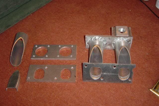
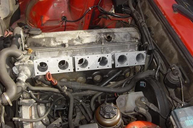
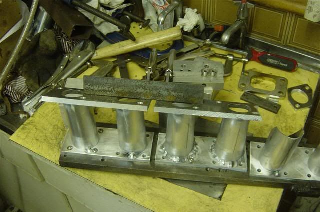
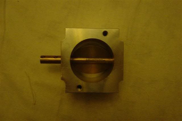
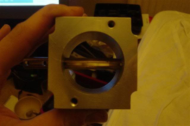
SO! Here's some component parts of the inlet manifolds and one which is about half done and has a throttle bolted to it.
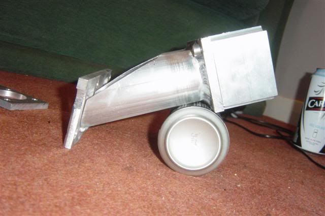
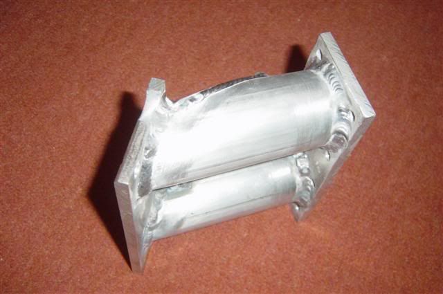
The half done mani from the side showing the angle of attack the runner has into the port. Believe it or not, the bottom of the runner lines up exactly with the bottom of the port.
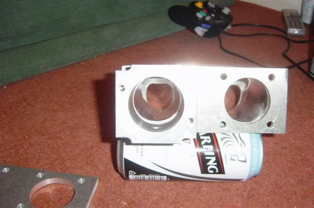
Here's a look down the throttle:
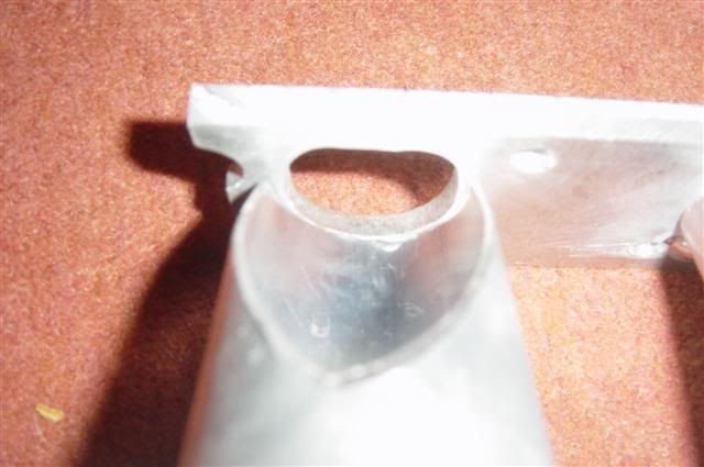
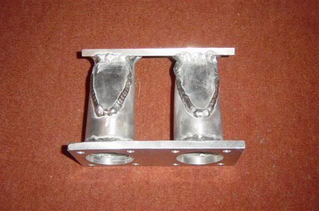
And one showing the transition from runner to head flange. The large hole will be filled by a welded plate (the thing which is kinda shield shaped in the first piccy) and the injector bosses will be welded to those plates. Advice when I was at Emerald was to move the injectors away from the head to get better mixing.
For anyone wondering why the runners are so long, it's because of that pesky thermostat housing which is very close to cyl1's port. Make the runners about 120mm long though and you've got all the room you could want
Did a trial fit of the E36 front hubs today. Looks like all that's needed is to modify the rear crud guard a bit and then make up a very simple sleeve to take the diameter of the spigot out. The E30 nut looks big enough and goes on 5 1/2 turns which is more than enough in my opinion
Think I'm going to need about a 3mm spacer behind the E46 330Ci brake discs to get enough clearance for the track rod ends but that's no great shakes. What does remain to be seen is whether the offset of the front wheels will need altering as there's about 13mm from the inner edge of the rim to the strut and, on an 8J rim I think I need the wheels as far into the arches as possible. Should just be a case of making up a set of spacers for the wheels so that the rim sits further in, will give me that nice staggered offset look too
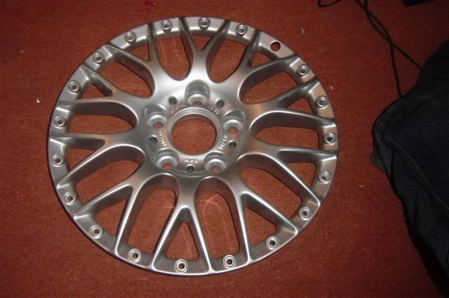
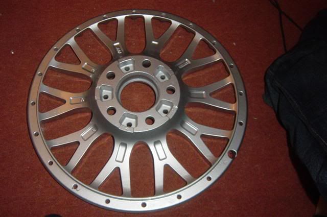
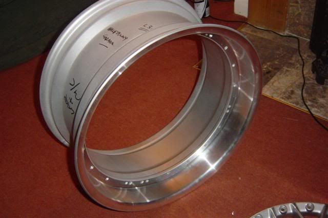
Finally, on a more aesthetic note, I had another go at dismantling the wheels today. I tried standing in them, levering at them and was about to resort to chemicals but thought I'd give a hammer a go. Found a nice rubber headed hammer and gave the back of the spokes a twat and, after several knocks the centre dropped out
I'm really torn now between making more manifolds for the throttles tomorrow or whether to attack the rim sections with the polish!
Oh yeah, and as an aside, I'm getting a Ford style heated windscreen for the car too. How cools is that ?!!
Anyway, little bit more progress after the belt broke on the lathe last weekend leaving me machineless
SO! Here's some component parts of the inlet manifolds and one which is about half done and has a throttle bolted to it.
The half done mani from the side showing the angle of attack the runner has into the port. Believe it or not, the bottom of the runner lines up exactly with the bottom of the port.
Here's a look down the throttle:
And one showing the transition from runner to head flange. The large hole will be filled by a welded plate (the thing which is kinda shield shaped in the first piccy) and the injector bosses will be welded to those plates. Advice when I was at Emerald was to move the injectors away from the head to get better mixing.
For anyone wondering why the runners are so long, it's because of that pesky thermostat housing which is very close to cyl1's port. Make the runners about 120mm long though and you've got all the room you could want
Did a trial fit of the E36 front hubs today. Looks like all that's needed is to modify the rear crud guard a bit and then make up a very simple sleeve to take the diameter of the spigot out. The E30 nut looks big enough and goes on 5 1/2 turns which is more than enough in my opinion
Think I'm going to need about a 3mm spacer behind the E46 330Ci brake discs to get enough clearance for the track rod ends but that's no great shakes. What does remain to be seen is whether the offset of the front wheels will need altering as there's about 13mm from the inner edge of the rim to the strut and, on an 8J rim I think I need the wheels as far into the arches as possible. Should just be a case of making up a set of spacers for the wheels so that the rim sits further in, will give me that nice staggered offset look too
Finally, on a more aesthetic note, I had another go at dismantling the wheels today. I tried standing in them, levering at them and was about to resort to chemicals but thought I'd give a hammer a go. Found a nice rubber headed hammer and gave the back of the spokes a twat and, after several knocks the centre dropped out
I'm really torn now between making more manifolds for the throttles tomorrow or whether to attack the rim sections with the polish!
Oh yeah, and as an aside, I'm getting a Ford style heated windscreen for the car too. How cools is that ?!!
-
Andy335Touring
- Married to the E30 Zone

- Posts: 7144
- Joined: Sun Jan 09, 2005 11:00 pm
- Location: Long Eaton,Nottingham
Looking sweet, no pod tomorrow then ?
-
maxfield
- Old Skooler

- Posts: 15186
- Joined: Sat Nov 26, 2005 11:00 pm
- Location: Mansfield
Looking good 
That Carling can reminds me
That Carling can reminds me

-
Turbo-Brown
- Boost Junkie
- Posts: 4705
- Joined: Tue Feb 15, 2005 11:00 pm
- Location: Aldershot, Hants
Cheers dude, no pod for me, I'm being a reclusive welder bee at the momentAndy335Touring wrote:Looking sweet, no pod tomorrow then ?
Poor Brown, it's the last chance he'd have had too
Is there nothing Carling can't support?!
-
Turbo-Brown
- Boost Junkie
- Posts: 4705
- Joined: Tue Feb 15, 2005 11:00 pm
- Location: Aldershot, Hants
Well, lack of Pod means I've now got this far with the inlet side of things:
Time to take some days off work to really get stuck into these bits
Time to take some days off work to really get stuck into these bits
-
jkarran
- E30 Zone Regular

- Posts: 327
- Joined: Thu Jan 12, 2006 11:00 pm
- Location: Isle of Man
Good progress, there's a huuuuge amount of work going into this, just watching from the 'web, it's easy to overlook the hours that each of these photo updates actually represents 
jk
jk
E30 320i Rally Turd - Usually broken
E24 635Csi - Rotting in peace for now
E34 540i - Daily driver
Blown R1 Striker - In progress
E24 635Csi - Rotting in peace for now
E34 540i - Daily driver
Blown R1 Striker - In progress
-
Turbo-Brown
- Boost Junkie
- Posts: 4705
- Joined: Tue Feb 15, 2005 11:00 pm
- Location: Aldershot, Hants
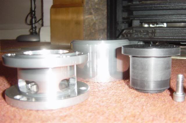
Forgot to borrow the camera this weekend, but have made the great big (56mm dia) cylinder for my great big 40mm dia dump-valve.
Also made and polished the last bit of the inlet air side of the charge cooler.
Also made and polished the last bit of the inlet air side of the charge cooler.
-
Gunni

- E30 Zone Addict
- Posts: 2115
- Joined: Tue Jan 11, 2005 11:00 pm
- Location: Oxford
sweet.
How´s the vacuum control system for the twin turbo coming along?
How´s the vacuum control system for the twin turbo coming along?
-
Turbo-Brown
- Boost Junkie
- Posts: 4705
- Joined: Tue Feb 15, 2005 11:00 pm
- Location: Aldershot, Hants
Just gotta get some more Tiggy tig gas and then I can start making the vacuum actuators.
Not really looked at the electronics despite JK kindly offering to help, will e-mail you the bits if you're still willing to have a look at them for me dude?
Other than that, got a single vee belt driven vac pump to go on.
Gonna start concentrating on actually finishing some of these bits off rather than just starting lots and lots of little bits!
Get the DV done, and them move onto the throttles. Everone likes throttles!
-
Yaninnya
- E30 Zone Regular
- Posts: 512
- Joined: Tue Aug 01, 2006 11:00 pm
- Location: Jersey, CI
No! Not everyone!Turbo-Brown wrote:Everone likes throttles!
Nice to see that the progress is continuous on your project, Alex.
BTW. Did you think about rest of the car? Mostly about the brakes and suspension?
Jan
-
Turbo-Brown
- Boost Junkie
- Posts: 4705
- Joined: Tue Feb 15, 2005 11:00 pm
- Location: Aldershot, Hants
Yaninnya wrote: No! Not everyone!
I'm going to keep the suspension kit I've already got which is the Bilstein Sprintline (if memory serves!) and hold on to the offset front bushes too as I like the way that Brown drives at the moment.
For the brakes, I'm using E30 M3 discs at the rear (no idea what size they are or indeed if they're any larger than 325i discs). On the front, I'm using the 325x22mm E46 330Ci discs and either the Wilwood calipers I've got on Brown (which are dust sealed) or possibly another set of Wilwood calipers I bought ages ago for the GT6 which are quite alot bigger.
Would prefer to keep the dust sealed calipers if I can though.
Think that should take care of the stopping requirements, the front discs really fill the front wheels nicely too
-
jkarran
- E30 Zone Regular
- Posts: 327
- Joined: Thu Jan 12, 2006 11:00 pm
- Location: Isle of Man
No problem. I'm just getting back into PICs anyway for another project so I'm a bit less rusty after a week or two reading and thinking.Turbo-Brown wrote:Not really looked at the electronics despite JK kindly offering to help, will e-mail you the bits if you're still willing to have a look at them for me dude?
jk
E30 320i Rally Turd - Usually broken
E24 635Csi - Rotting in peace for now
E34 540i - Daily driver
Blown R1 Striker - In progress
E24 635Csi - Rotting in peace for now
E34 540i - Daily driver
Blown R1 Striker - In progress
-
Turbo-Brown
- Boost Junkie
- Posts: 4705
- Joined: Tue Feb 15, 2005 11:00 pm
- Location: Aldershot, Hants
You're still about a million miles ahead of where I'll ever be with the darned things, JK 
So, this weekends spoils are.....the dump valve! Just needs a spring and a pipe connection in the top and it's done!
Here's the component parts:
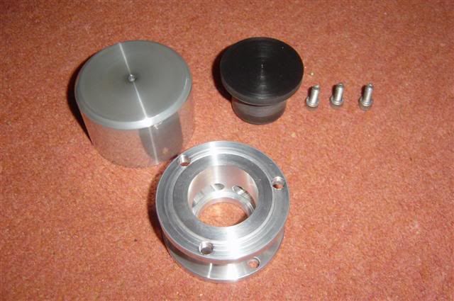
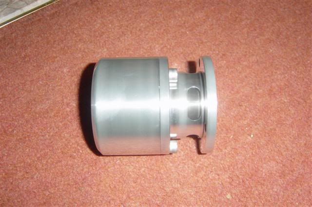
And the assembled valve:
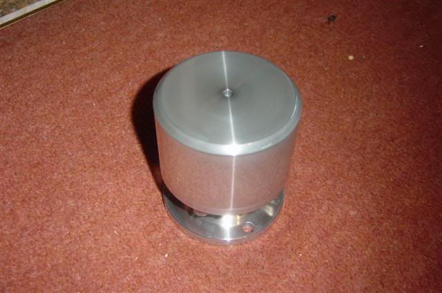
Looks a lot shinier in real life
So, this weekends spoils are.....the dump valve! Just needs a spring and a pipe connection in the top and it's done!
Here's the component parts:
And the assembled valve:
Looks a lot shinier in real life
-
Speedtouch
- Old Skooler
- Posts: 14099
- Joined: Tue Feb 14, 2006 11:00 pm
- Location: Canterbury
I have a couple of programs for the PIC 16F876 that provide PWM function (one with keyboard input and LCD display), if you're interested...
///M aurice
ECU Upgrade EPROM Chips, £40 posted within the UK. Note these are not Zone chips.
viewtopic.php?f=6&t=279421
ECU Upgrade EPROM Chips, £40 posted within the UK. Note these are not Zone chips.
viewtopic.php?f=6&t=279421
-
Turbo-Brown
- Boost Junkie
- Posts: 4705
- Joined: Tue Feb 15, 2005 11:00 pm
- Location: Aldershot, Hants
Now that is interesting! Does the keyboard input allow you to adjust the look-up table settings by any chance?
Being able to have a readout and also quick access to the table would be so handy!!!
Being able to have a readout and also quick access to the table would be so handy!!!
-
Speedtouch
- Old Skooler
- Posts: 14099
- Joined: Tue Feb 14, 2006 11:00 pm
- Location: Canterbury
AFAIK, the look-up table is set within the program, and the keyboard is used to select which section of the table is used, to give a corresponding change in Duty Cycle, or mark-space ratio of the PWM output signal.
Have sent copies of the files to the contact address in your 'air-in' website - hope this is OK?
Cheers,
Have sent copies of the files to the contact address in your 'air-in' website - hope this is OK?
Cheers,
///M aurice
ECU Upgrade EPROM Chips, £40 posted within the UK. Note these are not Zone chips.
viewtopic.php?f=6&t=279421
ECU Upgrade EPROM Chips, £40 posted within the UK. Note these are not Zone chips.
viewtopic.php?f=6&t=279421
-
Turbo-Brown
- Boost Junkie
- Posts: 4705
- Joined: Tue Feb 15, 2005 11:00 pm
- Location: Aldershot, Hants
Hey Maurice, got them through yesterday. Bit over my head at the moment but will have a good hard look at trying to understand what makes them tick
Can anyone shed any light on the kind of artificial slowing down of the frequency? I send a plea for help to Microchip who said the chips can't output as slow as 15Hz and that you need to slow them down using interrupts or something.
Can anyone shed any light on the kind of artificial slowing down of the frequency? I send a plea for help to Microchip who said the chips can't output as slow as 15Hz and that you need to slow them down using interrupts or something.
-
jkarran
- E30 Zone Regular
- Posts: 327
- Joined: Thu Jan 12, 2006 11:00 pm
- Location: Isle of Man
You can produce pretty much any waveform you can imagine so long as it's quite a bit lower frequency than the main clock crystal using built in timers and some simple software. You could also produce a 15Hz waveform using the hardware pwm output but you'd need to run the chip very slowly which limits you computing power so that's not the way to tackle it.
Have a think about what you want to achieve re. control strategy and adjustability then either post it up here or email and I'll go through some different possible implementations with you. Adding buttons to adjust tables and displays adds more complexity than you might imagine because you'll also need to access EEPROM memory which isn't mapped the same as the RAM though once you get into it and get the basics working (so you can see what's happening) it's not hard.
jk
E30 320i Rally Turd - Usually broken
E24 635Csi - Rotting in peace for now
E34 540i - Daily driver
Blown R1 Striker - In progress
E24 635Csi - Rotting in peace for now
E34 540i - Daily driver
Blown R1 Striker - In progress
-
Speedtouch
- Old Skooler
- Posts: 14099
- Joined: Tue Feb 14, 2006 11:00 pm
- Location: Canterbury
You could use dividers (flip-flops) to drop the output frequency. For instance, a watch crystal oscillates at 32,768Hz (2^15Hz), which is divided by 2 fifteen times over to give a 1Hz reference for the seconds.
Dividing the 20kHz signal of those PWM circuits by 2 ten times over gives an output frequency of around 20Hz...
Dividing the 20kHz signal of those PWM circuits by 2 ten times over gives an output frequency of around 20Hz...
///M aurice
ECU Upgrade EPROM Chips, £40 posted within the UK. Note these are not Zone chips.
viewtopic.php?f=6&t=279421
ECU Upgrade EPROM Chips, £40 posted within the UK. Note these are not Zone chips.
viewtopic.php?f=6&t=279421
-
Turbo-Brown
- Boost Junkie
- Posts: 4705
- Joined: Tue Feb 15, 2005 11:00 pm
- Location: Aldershot, Hants
Been burying my head a bit with the eletronics but will need to look at them again soon I think, I'm just not getting it
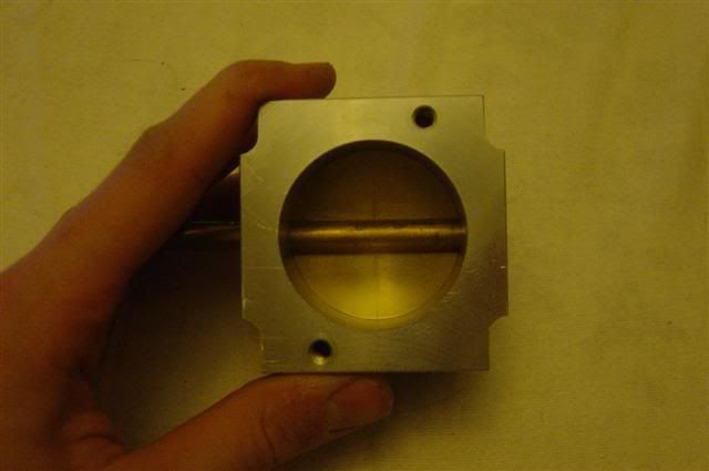
Anyway, not had an amasingly productive weekend, but have managed to close off one of the inlet manifolds and get another to about 50% completion before running out of gas. Couldn't figure out why the weld just would take on the last one until I flicked the gauge on the bottle which made it drop to zero
So, here's the most complete manifold which just needs injector bosses and fuel rail ties welding on
-
Onz
- E30 Zone Regular
- Posts: 836
- Joined: Sat Aug 26, 2006 11:00 pm
looking good mate, ill look forward to seeing this dynoed!
-
appletree
- E30 Zone Addict
- Posts: 3482
- Joined: Fri Jan 20, 2006 11:00 pm
- Location: Retford
Just out of intrest has there been much distortion on the plate were it will mate to the head or are you going to skim them in a milleing machine???
looking
looking

You should never underestimate the predictability of stupidity
M42 Supercharged 285bhp + M3 6speed box
-
Turbo-Brown
- Boost Junkie
- Posts: 4705
- Joined: Tue Feb 15, 2005 11:00 pm
- Location: Aldershot, Hants
Cheers guys, can't wait to get the thing up and running myself!
I'm gonna get the manifolds all jigged up and skimmed to just make sure the angles are all the same, but amasingly the plates have all stayed pretty much dead flat.
All I've been doing is clamping them down to a plank of steel about 3/4" thick which has been doing the trick nicely
I'm gonna get the manifolds all jigged up and skimmed to just make sure the angles are all the same, but amasingly the plates have all stayed pretty much dead flat.
All I've been doing is clamping them down to a plank of steel about 3/4" thick which has been doing the trick nicely
-
jkarran
- E30 Zone Regular
- Posts: 327
- Joined: Thu Jan 12, 2006 11:00 pm
- Location: Isle of Man
That'll be a nice heatsink. I wish I'd done that, mine looked like a curly wurly when I'd finished welding up my runnersTurbo-Brown wrote:All I've been doing is clamping them down to a plank of steel about 3/4" thick which has been doing the trick nicely
jk
E30 320i Rally Turd - Usually broken
E24 635Csi - Rotting in peace for now
E34 540i - Daily driver
Blown R1 Striker - In progress
E24 635Csi - Rotting in peace for now
E34 540i - Daily driver
Blown R1 Striker - In progress
-
Turbo-Brown
- Boost Junkie
- Posts: 4705
- Joined: Tue Feb 15, 2005 11:00 pm
- Location: Aldershot, Hants
Aah, the other thing I've been doing is jigging everything up, clamping to my plank of steel and then putting the whole lot on the gas stove for a while to bring it up to temperature. Makes welding thicker stuff to thinner stuff SO much easier!
Nice gauge of when the metal's ready to weld is touching a piece of wood against it. If the wood gets a scorch mark on it, the metal's ready to weld
Nice gauge of when the metal's ready to weld is touching a piece of wood against it. If the wood gets a scorch mark on it, the metal's ready to weld
-
Turbo-Brown
- Boost Junkie
- Posts: 4705
- Joined: Tue Feb 15, 2005 11:00 pm
- Location: Aldershot, Hants
Ooh, had a reeeeealy bad hangover on Saturday after we threw a haloween party so haven't managed to do much this weekend.
Have badgered out the spindles, and made one butterfly. Most of the time was spend making the tooling for the spindles, but last time it took a few boring days with a tiny little slot drill to make spindles, this time it took about an hour for all six. Tooling is time well spent!
Quite pleased to have a butterfly done as they're some of the most accurate (read time consuming) parts I make. Only five left
Typed PWM CONTROLLER into the internet during my hangover yesterday too. It came up with a little 12v 555-based PWM controller which uses a variable resistor as a reference and costs about £2 to make so I might give that a try. Seems it's frequency is set by a capacitor, think you can get variable caps can't you? If so it should make the thing a little more tunable....I hope!
Basically all I want from this PWM controller is to prevent the air divertor from just banging open as soon as the large turbo starts boosting leading to a sudden drop in boost overall. Fingers crossed for the simple solution!
-
Speedtouch
- Old Skooler
- Posts: 14099
- Joined: Tue Feb 14, 2006 11:00 pm
- Location: Canterbury
Nice work! Alas, variable capacitors only come in values up to around 1500pF (1n5F) since they used to be used for tuning radio front ends prior to digital PLL tuners, hence probably won't be much use on a 555 timer circuit; in the one I think you're referring to, C1 is 0.047uF/0.1uF = 47/100nF, way bigger than variable capacitors...
http://www.mainlinegroup.co.uk/jacksonb ... 5720br.htm
http://www.mainlinegroup.co.uk/jacksonb ... 5720br.htm
///M aurice
ECU Upgrade EPROM Chips, £40 posted within the UK. Note these are not Zone chips.
viewtopic.php?f=6&t=279421
ECU Upgrade EPROM Chips, £40 posted within the UK. Note these are not Zone chips.
viewtopic.php?f=6&t=279421
-
Yaninnya
- E30 Zone Regular
- Posts: 512
- Joined: Tue Aug 01, 2006 11:00 pm
- Location: Jersey, CI
Hi Alex,Turbo-Brown wrote:Have badgered out the spindles, and made one butterfly. Most of the time was spend making the tooling for the spindles, but last time it took a few boring days with a tiny little slot drill to make spindles, this time it took about an hour for all six. Tooling is time well spent!
IMO you shoud reduce the diameter of spindle in area where the throttle is. It don't need to be so big and you will reduce the drag (you can reduce it near by half I think; what is the diameter of spindle?).
Jan
-
Turbo-Brown
- Boost Junkie
- Posts: 4705
- Joined: Tue Feb 15, 2005 11:00 pm
- Location: Aldershot, Hants
Aah, is there some way of gangint capacitors to increase their overall value? or is that just resistors?
Hey Jan, how's it going?
There's a fair amount of work to do to the spindles before they're ready to use, including drilling and tapping them for the butterfly bolts, welding an arm onto each one and machining them down to reduce restriction as you say.
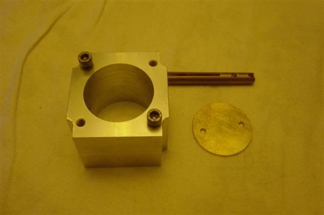
The spinldes are 10mm diameter which is quite large! The reason behond that is I designed the throttles to have one sided spindles like this (in the bottom right of the picture):

Only problem being that I don't think brass is strong enough to do that with so I made the ones pictured there from stainless steel which is a pain to machine and I can't be bothered to go through it all again, especially as I'm not paying myself to make these ones
Hey Jan, how's it going?
There's a fair amount of work to do to the spindles before they're ready to use, including drilling and tapping them for the butterfly bolts, welding an arm onto each one and machining them down to reduce restriction as you say.
The spinldes are 10mm diameter which is quite large! The reason behond that is I designed the throttles to have one sided spindles like this (in the bottom right of the picture):
Only problem being that I don't think brass is strong enough to do that with so I made the ones pictured there from stainless steel which is a pain to machine and I can't be bothered to go through it all again, especially as I'm not paying myself to make these ones
Last edited by Turbo-Brown on Mon Oct 29, 2007 7:27 am, edited 1 time in total.
-
Speedtouch
- Old Skooler
- Posts: 14099
- Joined: Tue Feb 14, 2006 11:00 pm
- Location: Canterbury
Yeah, you used to be able to buy ganged variable capacitors; in theory just connecting them in parallel will increase the overall capacitance. Snag is, they're not ideally suited to an automotive environment unless well sealed in a casing because the vanes (on air-dielectric type) tend to collect dust, metal particles, etc.
///M aurice
ECU Upgrade EPROM Chips, £40 posted within the UK. Note these are not Zone chips.
viewtopic.php?f=6&t=279421
ECU Upgrade EPROM Chips, £40 posted within the UK. Note these are not Zone chips.
viewtopic.php?f=6&t=279421
-
Yaninnya
- E30 Zone Regular
- Posts: 512
- Joined: Tue Aug 01, 2006 11:00 pm
- Location: Jersey, CI
That is exactly what I mean. In part open throttle the bigger width of spindle doesn't matter. The flow is restricted then by the butterfly.Turbo-Brown wrote:The spinldes are 10mm diameter which is quite large! The reason behond that is I designed the throttles to have one sided spindles like this (in the bottom right of the picture):
Jan
-
jkarran
- E30 Zone Regular
- Posts: 327
- Joined: Thu Jan 12, 2006 11:00 pm
- Location: Isle of Man
If you can dedicate some time to the PIC solution it is your best option (besides finding extra PWM OP channels from your ecu). It should however be easy enough to make an analogue controller though it'll never be as adjustable and versatile as the PIC could be.
All variable components in a car are a potential sorce of problems down the line, they don't like harsh environments and tend to be quite fragile and unreliable in real world situations. The best bet is to set up with variable components, measure their values then substitute fixed devices when you're happy. PWM generators are easy to make and can be tuned by varying resistances (variable R is much more common, versatile and robust than variable C) instead of varying capacitors.
Is the controller basically looking at 2 pressure sensors, when the big turbo one reads higher than the little turbo one you want to start opening the butterfly? In principal this is easy to do but the problem will be stability, it'll need careful tuning to make sure it doesn't continually oscilate between open and shut yet opens quickly enough to do the rest of the engine justice. Do you have a pressure sensor in mind, if so pop up the part no.? Also, what PWM freq do you need, I guess pretty low for the solenoids, 30-50Hz? Will increasing or decreasing duty cycle (basically controller output power) open the butterfly valve?
<edit> Additional consideration will need to be given to making sure the butterfly behaves correctly once both turbos are up and running then shuts again when the throttle shuts since the pressure will be equal either side. It's an interesting and complex problem.
jk
E30 320i Rally Turd - Usually broken
E24 635Csi - Rotting in peace for now
E34 540i - Daily driver
Blown R1 Striker - In progress
E24 635Csi - Rotting in peace for now
E34 540i - Daily driver
Blown R1 Striker - In progress
-
Speedtouch
- Old Skooler
- Posts: 14099
- Joined: Tue Feb 14, 2006 11:00 pm
- Location: Canterbury
Agreed, variable resistor adjustment is preferable to variable capacitor, being more durable and cheaper.
Maybe you could adapt an E34 heater control since it provides a PWM output to open and close solenoid operated heater valves at around the frequency you're aiming at.
http://cgi.ebay.co.uk/BMW-E34-5-SERIES- ... dZViewItem
http://cgi.ebay.co.uk/BMW-5-series-E34- ... dZViewItem
Maybe you could adapt an E34 heater control since it provides a PWM output to open and close solenoid operated heater valves at around the frequency you're aiming at.
http://cgi.ebay.co.uk/BMW-E34-5-SERIES- ... dZViewItem
http://cgi.ebay.co.uk/BMW-5-series-E34- ... dZViewItem
///M aurice
ECU Upgrade EPROM Chips, £40 posted within the UK. Note these are not Zone chips.
viewtopic.php?f=6&t=279421
ECU Upgrade EPROM Chips, £40 posted within the UK. Note these are not Zone chips.
viewtopic.php?f=6&t=279421