Twin Seq. Dry sumping for beginners :D

Discuss general engine, turbo and supercharger conversions in this section

Moderator: martauto

Post Reply
jkarran
E30 Zone Regular
E30 Zone Regular
Posts: 327
Joined: Thu Jan 12, 2006 11:00 pm
Location: Isle of Man

Thu Aug 30, 2007 12:33 am

I seem to have been banned from posting from work, something about a script attack. Arse :x

No preheating used on that TurboBrown, just ramp the current up for a few seconds before allowing the puddle to form.

The tig takes some getting used to but when you do it's a hell of a tool. I had next to no practical experience on a mig or oxy-acetylene welder but it was trivially easy to start welding steel with the tig. Alloy took more practice, perhaps 2 weeks of evenings spread over a few months. It's exceptionally frustrating, impossible even at first but once you realise that you can stop things getting out of hand by quickly backing off the pedal it all falls into place. The oxides spoiling your seam are a pain in the ass but careful cleaning helps a lot especially after the workpiece has got hot.

They're not cheap though to buy or run, mine uses a worrying amount of argon. I'd have had my alloy bits welded by local fabricator at very reasonable rates but he emigrated forcing me to learn.
jk
E30 320i Rally Turd - Usually broken
E24 635Csi - Rotting in peace for now
E34 540i - Daily driver
Blown R1 Striker - In progress
Turbo-Brown
Boost Junkie
Posts: 4705
Joined: Tue Feb 15, 2005 11:00 pm
Location: Aldershot, Hants
Contact:

Thu Aug 30, 2007 10:42 pm

What sort of gas flow do you use JK?

I used to absolutely CANE gas with my set until one day the bottle was running really low, but the welds were fine despite the tiny amount of gas coming out. Problem I have now is that the reg keeps changing and upping the flow :(

Anyway, on some project related news, I've been playing with the PIC tonight trying to get my head around this ports thing.

The board in the kit has 4 LEDs which are connected to pins 0-3 of PORTC.

The first lesson (they're crap as lessons go, largely involving you loading up a program from a CD, burning it to the PIC and then the lesson going "there; that works now, isn't that wonderful and haven't you learned a lot?! winkeye " )...anyway, the first lesson tells the LED which is connected to pin 0 or PORTC to come on.

I've got my head around telling PORTC that it's an output so I thought it would be a simple case of copying the line of program which tells pin 0 to go high, changing the 0 for a 1, and thereby making both the first and second LEDs light up.

Alas, the second one comes on, but the first one goes off :cry:

Think I've got quite some way to go before I can get an analogue input to give a PWM output! :lol:

If anyone knows what I'm on about or where I might be going wrong, pleeeease shout!
325i Twin Turbo (until 10am 01/12/07 :( )

www.air-in.co.uk free M20 exhaust and inlet flange
jkarran
E30 Zone Regular
E30 Zone Regular
Posts: 327
Joined: Thu Jan 12, 2006 11:00 pm
Location: Isle of Man

Fri Aug 31, 2007 6:40 pm

IIRC ports that are shared analogue/digital are configured to analogue inputs as default, this is a safe condition to start in for most applications.

You'll need to configure the whole of port C to digital (or at least the 4 port C pins with LEDs) then configure them as outputs then write your data to the port to control the LEDs

you can do all of this this a bit or byte ata time, I can't recall the exact commands or register names and I wouldn't want to confuse you by getting one wrong.

Post which device you're using and I can have a flick through the datasheet, It's mostly straightforward once you get the hang of what's what but there's a few annoying little traps you can stumble into.

If you can get a button to control an led then add some time delays (loops and counters) and then maybe some basic logic using 2 or 3 button inputs to control an led or two then you're well on your way to understanding. After that have a go at the ADC, it's pretty simple to use. Then try PWM, this requires more thought than the other bits and is the bit I have least experience of. Personally I'd avoid interupts, they can be useful but you can really shoot yourself in the foot with them. The code to control your solenoid should be pretty simple but I'd certainly learn the basics bit by bit first. These chips are cheap and hugely versatile once you get to grips with them.

Assigning sensible names to variables and pins helps when you have to go back to your code in a couple of years and the memory is rusty. I can't remember how though. Adding meaningful comments is also essential even while learning, it'll remind you what you were trying to acchieve even if it goes wrong.

I have loads of info and code examples at work but I'm still banned by the mods :x
E30 320i Rally Turd - Usually broken
E24 635Csi - Rotting in peace for now
E34 540i - Daily driver
Blown R1 Striker - In progress
jkarran
E30 Zone Regular
E30 Zone Regular
Posts: 327
Joined: Thu Jan 12, 2006 11:00 pm
Location: Isle of Man

Fri Aug 31, 2007 7:34 pm

If you're writing a byte to the output port (using something like the 'movwf' command as opposed to setting individual bits with the 'bsf' command) to turn on the LEDs you'll be turning the first LED on by writing a binary sequence like 00000001 then 1uS later you'll be turning it off and turning the next one on with a binary sequence like 00000010

The bold bit represents your initial LED. you could be using the hexidecimal representation 0x01 for the first LED and 0x02 for the second. Try 0x03, that will set both of the two least significant bits.

Read up on hexidecimal and binary notation, it's your friend and will help loads to have it fresh in your mind when programming in assembly languages.
jk
E30 320i Rally Turd - Usually broken
E24 635Csi - Rotting in peace for now
E34 540i - Daily driver
Blown R1 Striker - In progress
bigkev
E30 Zone Regular
E30 Zone Regular
Posts: 612
Joined: Wed Jul 27, 2005 11:00 pm
Location: hibernating till summer

Fri Aug 31, 2007 9:35 pm

you must be loaded jkarran, you own a pool table :D

nice work by the way :cool:
Image
Turbo-Brown
Boost Junkie
Posts: 4705
Joined: Tue Feb 15, 2005 11:00 pm
Location: Aldershot, Hants
Contact:

Sat Sep 01, 2007 1:20 am

That's a full blown snooker table isn't it? :lol:

I'm using the PIC 16F690 which came with the kit. It's got ADC and PWM so it seemed to fit my bill as it were.

I had a quick go at plugging 0x03 into the TRISC and PORTC things and that brought the 4th LED on :(

I'd really like to gain some understanding of the programming of these things, just out of interest! Think it's useful to know what's going on behind the scenes too when it comes to developing any kind of system.

Cheers for your help JK :cool:
325i Twin Turbo (until 10am 01/12/07 :( )

www.air-in.co.uk free M20 exhaust and inlet flange
Turbo-Brown
Boost Junkie
Posts: 4705
Joined: Tue Feb 15, 2005 11:00 pm
Location: Aldershot, Hants
Contact:

Sat Sep 01, 2007 1:23 am

Hmmmm, it's not something to do with the _config thing is it? I've absolutely NO idea what the stuff on that line means!

Also, i'm not really getting my head around what the reguisters do.

The program which makes the 4th LED come on goes as follows:

#include <p16F690.inc>
__config (_INTRC_OSC_NOCLKOUT & _WDT_OFF & _PWRTE_OFF & _MCLRE_OFF & _CP_OFF & _BOR_OFF & _IESO_OFF & _FCMEN_OFF)
org 0
Start:
bsf STATUS,RP0 ; select Register Page 1
bcf TRISC,0x03 ; make IO Pin C3 an output
bcf STATUS,RP0 ; back to Register Page 0
bsf PORTC,0x03 ; turn on LED C1 (DS4)
goto $ ; wait here
end

Although the 0x03 said just '0' in the example file and made the 1st LED (DS1) come on.
325i Twin Turbo (until 10am 01/12/07 :( )

www.air-in.co.uk free M20 exhaust and inlet flange
Turbo-Brown
Boost Junkie
Posts: 4705
Joined: Tue Feb 15, 2005 11:00 pm
Location: Aldershot, Hants
Contact:

Sat Sep 01, 2007 1:32 am

Aaaaaaaaaaaaaaaaaaaaaaaaaaaaaaaaaaaaaaaaaaah!

It suddenly clicked!

Because the 1st LED in the program was just flicking on as you said, and the the 2nd was coming on after the first before the program ended, all it needed was to be sent back to the start to get two LEDs to light up so I've got this now:

#include <p16F690.inc>
__config (_INTRC_OSC_NOCLKOUT & _WDT_OFF & _PWRTE_OFF & _MCLRE_OFF & _CP_OFF & _BOR_OFF & _IESO_OFF & _FCMEN_OFF)
org 0
Start:
bsf STATUS,RP0 ; select Register Page 0
bcf TRISC,0x02 ; make IO Pin C1 an output
bcf STATUS,RP0 ; back to Register Page 0
bsf PORTC,2

bsf STATUS,RP0 ; select Register Page 1
bcf TRISC,0x03 ; make IO Pin C1 an output
bcf STATUS,RP0 ; back to Register Page 1
bsf PORTC,3

goto Start ; wait here
end


I'll go through and annotate it so i don't forget why it works now!

Aah, a tiny milestone for me :D
325i Twin Turbo (until 10am 01/12/07 :( )

www.air-in.co.uk free M20 exhaust and inlet flange
jkarran
E30 Zone Regular
E30 Zone Regular
Posts: 327
Joined: Thu Jan 12, 2006 11:00 pm
Location: Isle of Man

Sat Sep 01, 2007 12:58 pm

The _config line sets up the processer

__config (_INTRC_OSC_NOCLKOUT & _WDT_OFF & _PWRTE_OFF & _MCLRE_OFF & _CP_OFF & _BOR_OFF & _IESO_OFF & _FCMEN_OFF)

Basically in order they appear: (internal oscilator selected and not routed to a pin on the chip & watchdog timer off & powerup timer off & master reset pin disabled & code protection off & low supply voltage reset dissabled & fu*k knows & fu*k knows)

They're all fine for now. Ultimately you'll want the Watchdog and Powerup timer and Brownout reset enabled to prevent problems in the car but don't touch them yet, it'll stop working at all if you set them wrong!

The opperation of the PIC peripherals including its IO pins is controlled by RAM registers, some contain setup info, some contain data that is mirrored to the IO pins and some contain data gathered from timers ADC etc. With user RAM there's too many to address directly so they're arranged into pages called banks. STATUS register bit RP0 allows you to switch between banks to adjust the registers you need to control the IO.

TRISC in bank 1 controls the direction of the PortC pins, a bit set to '1' is an input and a '0' an output. You can set or clear individual bits using the bsf or bcf commands with the syntax:

bcf TRISC,6 for example, this clears (sets to 0) bit 6 (bits are referenced 0 to 7, not 1 to 8 ) in the TRISC register leaving it with x0xxxxxx in it where x represents unchanged bits that were there before.

For example to turn Port C pin 0 and pin 2 on you need to do the following:

#include <p16F690.inc>
__config (_INTRC_OSC_NOCLKOUT & _WDT_OFF & _PWRTE_OFF & _MCLRE_OFF & _CP_OFF & _BOR_OFF & _IESO_OFF & _FCMEN_OFF)
org 0
Start:
bsf STATUS,RP0 ; select Register Page 1 there the TRISx direction reg are
bcf TRISC,0 ; make IO Pin C0 an output
bcf TRISC,2 ; make IO Pin C2 an output
bcf STATUS,RP0 ; back to Register Page 0 where the PORTx data registers are
bsf PORTC,0 ; turn on pin C0 and whatever is connected to it
bsf PORTC,2 ; turn on pin C2 and whatever is connected to it
goto $ ; wait here in an eternal loop repeating this instruction
end

Read the general description, IO ports, memmory arrangement and commands sections of the data sheet to get a good feel for exactly what you're doing with this, it's heavy going but will help no end :chuckle:

jk
E30 320i Rally Turd - Usually broken
E24 635Csi - Rotting in peace for now
E34 540i - Daily driver
Blown R1 Striker - In progress
Turbo-Brown
Boost Junkie
Posts: 4705
Joined: Tue Feb 15, 2005 11:00 pm
Location: Aldershot, Hants
Contact:

Sun Sep 02, 2007 10:40 pm

Good grief, it really is heavy going!

Just popped the program above onto the PIC and it made the 3rd LED come on but not the first, guess it's the GOTO at the end which causes this as if I reverse the last two BSF commands, it swaps the LED which comes on, taking the last BSF thing as the one that gets left on.

Is the GOTO $ to tell it to start again or something?

I'm just concerned that I'm bodging it by telling the program to GOTO Start:.

Also interesting is that if I set the registers twice, once for each TRICS,x... the LEDs which come on share the same brightness, whereas if both TRISC things happen between the register commands, the 1st LED comes on brighter than the others.

Anyway, in other news which I do vaguely understand, the piccies from the previous pages are fixed now :D

Also, I've just finished a project for someone else which means I've got loooots more free time on my hands to get on with this! :)

Cheers for your help JK, it's very much appreciated!
325i Twin Turbo (until 10am 01/12/07 :( )

www.air-in.co.uk free M20 exhaust and inlet flange
mattG
E30 Zone Camper
E30 Zone Camper
Posts: 1231
Joined: Tue Jul 04, 2006 11:00 pm
Location: Surrey

Sun Sep 02, 2007 11:27 pm

This is getting over my head but :cool:
Image

(\__/)
(='.'=)Simon13 wrote:
323's were dangerous this will un drivable in the wet!

MattG - hedgefinding specialist
E21 turbo

Can be your new sig matt!
jkarran
E30 Zone Regular
E30 Zone Regular
Posts: 327
Joined: Thu Jan 12, 2006 11:00 pm
Location: Isle of Man

Mon Sep 03, 2007 10:04 pm

I'm pretty sure the code eg I posted should give two LEDs on brightly

It configures both pins as outputs, swaps banks to allow access to the PORTC data register then sets the two output pins high. If that only lights one LED I suspect the pins set high aren't both connected to LEDs :?

What's the name of the kit you're using?

It's a steep learning curve but it'll come together pretty quickly once you get your head around the basics. Don't be put off by my ramblings, I haven't written any .asm code for a year or so and it's easy to forget small but vital details.

goto $ repeats itself, it's basically saying goto this address which it obviously continues to do for ever, it should stall the program.

jk
E30 320i Rally Turd - Usually broken
E24 635Csi - Rotting in peace for now
E34 540i - Daily driver
Blown R1 Striker - In progress
Turbo-Brown
Boost Junkie
Posts: 4705
Joined: Tue Feb 15, 2005 11:00 pm
Location: Aldershot, Hants
Contact:

Wed Sep 05, 2007 2:08 pm

Hmmm, the odd thing is that the LED corresponding to the last pin that's set high is the one that stays on :?

The kit's call the PIC Kit-2 which has a little board connecting LEDs DS1-DS4 to pins RC0-RC3

Gonna have to read up on this registers thing again I think, it's still not sticking in my brain :cry:

Anyway, on the bright side, I've just ordered a heavy duty polishing kit and a better finishing kit than I've already got so that I can make the wheel rims (if I can get them apart) and all the other ali bits I'm making soooooper shiny.

Bling!!!! :D
325i Twin Turbo (until 10am 01/12/07 :( )

www.air-in.co.uk free M20 exhaust and inlet flange
Turbo-Brown
Boost Junkie
Posts: 4705
Joined: Tue Feb 15, 2005 11:00 pm
Location: Aldershot, Hants
Contact:

Thu Sep 06, 2007 8:50 pm

Hmmmm, does the

goto $ tell the PIC to goto the current instruction and loop that rather than looping the whole thing?

Makes sense in my mind as the current instruction would be the last one executed before the goto, hence the last LED staying on?
325i Twin Turbo (until 10am 01/12/07 :( )

www.air-in.co.uk free M20 exhaust and inlet flange
Turbo-Brown
Boost Junkie
Posts: 4705
Joined: Tue Feb 15, 2005 11:00 pm
Location: Aldershot, Hants
Contact:

Thu Sep 06, 2007 10:33 pm

Just sent an e-mail to Microchip in teh vein hope that someone at the other end would go "duuuur! It's simple and here's ll the code to make it work"

However, what I got (and it is useful) is that you can't get the PIC to generate a 15 or so Hz PWM output without cheating and using a delay loop rather than the oscillator which is what I probably would've done.....so they've saved me the bother :lol:
325i Twin Turbo (until 10am 01/12/07 :( )

www.air-in.co.uk free M20 exhaust and inlet flange
jkarran
E30 Zone Regular
E30 Zone Regular
Posts: 327
Joined: Thu Jan 12, 2006 11:00 pm
Location: Isle of Man

Fri Sep 07, 2007 11:15 am

I can post from work again where I have MPLab setup. Send me the code and a description of what happens LED wise and what pins they're wired to. I'll pm my email address.
jk
E30 320i Rally Turd - Usually broken
E24 635Csi - Rotting in peace for now
E34 540i - Daily driver
Blown R1 Striker - In progress
Turbo-Brown
Boost Junkie
Posts: 4705
Joined: Tue Feb 15, 2005 11:00 pm
Location: Aldershot, Hants
Contact:

Fri Sep 07, 2007 1:13 pm

Cheers dude, received your PM.

Only got the bits at home so I'll e-mail them over the weekend if that's alright?

Thank you so much for your help on all of this dude :cool:
325i Twin Turbo (until 10am 01/12/07 :( )

www.air-in.co.uk free M20 exhaust and inlet flange
jkarran
E30 Zone Regular
E30 Zone Regular
Posts: 327
Joined: Thu Jan 12, 2006 11:00 pm
Location: Isle of Man

Fri Sep 07, 2007 3:13 pm

No problem, it's a cool project. It'll be Tuesday before I get to look through them though.
jk
E30 320i Rally Turd - Usually broken
E24 635Csi - Rotting in peace for now
E34 540i - Daily driver
Blown R1 Striker - In progress
Turbo-Brown
Boost Junkie
Posts: 4705
Joined: Tue Feb 15, 2005 11:00 pm
Location: Aldershot, Hants
Contact:

Sat Sep 08, 2007 7:24 pm

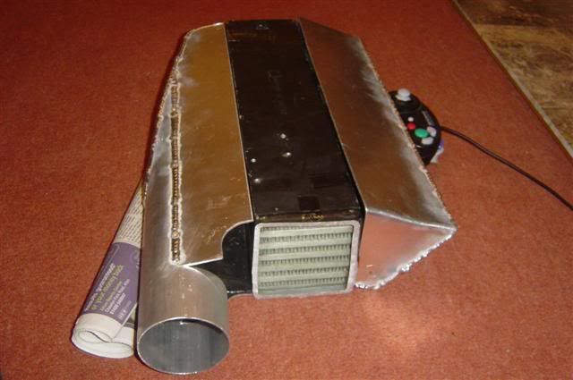
Had a nice day of fabrication and welding today, working on the charge cooler.

Think it's coming together quite nicely now I'm vaguely getting the hang of TIG welding. Have adjusted the %EN setting a little bit to give better penetration and a flatter weld. Seems to be doing the trick :D

Here's what it'll look like....ish:

Image


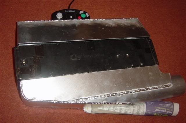
Same thing from a different angle:

Image


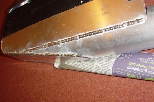
And lastly some weldy welds. Just gotta get the hang of tacking things together. Always seem to end up with a great big blob of weld :(

Image
325i Twin Turbo (until 10am 01/12/07 :( )

www.air-in.co.uk free M20 exhaust and inlet flange
appletree
E30 Zone Addict
E30 Zone Addict
Posts: 3482
Joined: Fri Jan 20, 2006 11:00 pm
Location: Retford

Sat Sep 08, 2007 7:33 pm

looking stunning, just a bit of advise.

try and get a bigger pump than you think you will need if that makes sense.

I used a positive displacement 12.5ltr per minute pump which gets hot pumping the water through the system which is all in 10mm airline, a twin pump system might have been better one to pump it through the charger cooler and then a second one after that to pump it through the cooling rad?

also volvo 440 auto transmition coolers are very good, big, thin and easy to mount!!

If your going to the Santa Pod show come and have a look! :D
Last edited by appletree on Sat Sep 08, 2007 8:52 pm, edited 1 time in total.
Image

You should never underestimate the predictability of stupidity

M42 Supercharged 285bhp + M3 6speed box
Turbo-Brown
Boost Junkie
Posts: 4705
Joined: Tue Feb 15, 2005 11:00 pm
Location: Aldershot, Hants
Contact:

Sat Sep 08, 2007 7:50 pm

Cheers for the advice Matt :D I was planning to use something like a bilge pump from a boat. Seems you can get them for about £30 and they'll pump 2000 gallons per hour. They're also submersible so that should (hopefully) keep it cool :D

What sort of dims is the 440 rad dude?

I'd been thinking of using a motorbike rad as I imagine they're quite efficient.

Cool wrie up in PPC by the way :cool:
Last edited by Turbo-Brown on Sun Sep 09, 2007 12:55 am, edited 1 time in total.
325i Twin Turbo (until 10am 01/12/07 :( )

www.air-in.co.uk free M20 exhaust and inlet flange
appletree
E30 Zone Addict
E30 Zone Addict
Posts: 3482
Joined: Fri Jan 20, 2006 11:00 pm
Location: Retford

Sat Sep 08, 2007 9:01 pm

I'll check on the dimensions for you, the only probs with the motor bike rad is they all have the cap to fill them on so its abit acward to mount anywere, although with your fabrication skills i'am sure you could just blaze a plate over it winkeye

i,ve got 8 brand new huge ally black rads from a industrial aircon units what my dad bought to do a garage heatin system ages ago but dint use in the end which is what i realy wanted to use as it fits perfectly between the chassis rails but would have ment me lowering the mounts for the engines rad by 2" to fit it under the bonnet but that would have been easily big enough and also held alot of water!!! if you want a look at one i could bring one to the pod, if you though you would want to lower the mounts or trim one down abit? my dad only wants abit for them nothing stupid.
Image

You should never underestimate the predictability of stupidity

M42 Supercharged 285bhp + M3 6speed box
kam-325i
E30 Zone Team Member
Posts: 4851
Joined: Tue Sep 27, 2005 11:00 pm
Location: TELFORD !!!! (Shropshire) Stevetigger Land !!!
Contact:

Sat Sep 08, 2007 11:22 pm

Turbo-Brown wrote:What sort of gas flow do you use JK?

I used to absolutely CANE gas with my set until one day the bottle was running really low, but the welds were fine despite the tiny amount of gas coming out. Problem I have now is that the reg keeps changing and upping the flow :(
For TIG welding of Aluminium, you'll want an ideal flow rate of 5-7 Lpm, anymore than 9-10 Lpm and you will start to introduce air into the weld area.

For MIG welding, around 10-15 Lpm.
Pete don't care about colour, He would shag a rainbow if he could find the end of it....
Image
Turbo-Brown
Boost Junkie
Posts: 4705
Joined: Tue Feb 15, 2005 11:00 pm
Location: Aldershot, Hants
Contact:

Sun Sep 09, 2007 6:23 pm

Little bit more progress today:

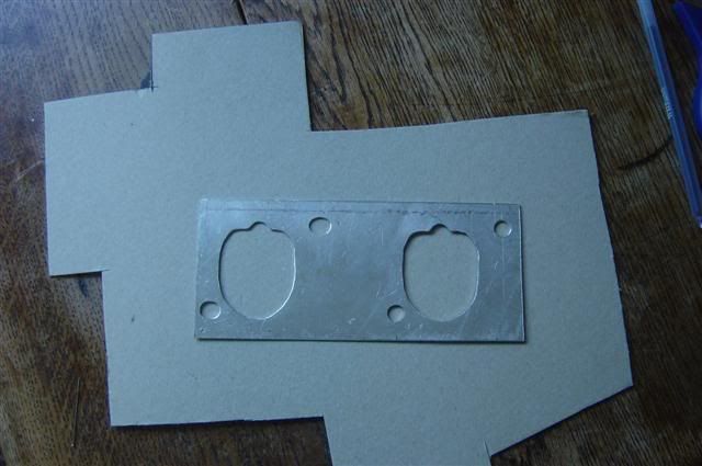
been making a start on the throttle body manifolds.

Here's the template I made for the last set to score around:

Image


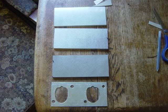
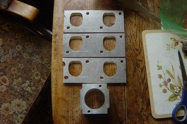
The 8mm thick blanks ready for drilling and lots of filing:

Image


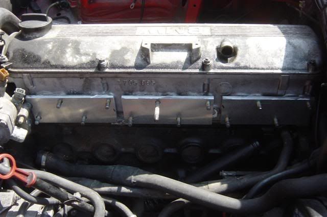
The drilled blanks on the head. The front most one is shaped to clear the thermostat housing. Great for air flow like this :)

Image


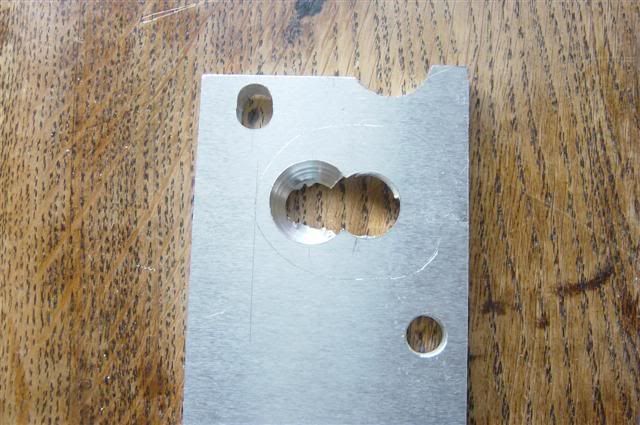
Anyway, once they fit, ya drills a couple of 20mm holes in them to give this and let you get a grrrreat big file in:

Image


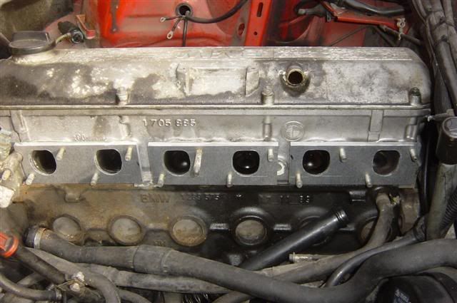
And after about 15 or 20 mins on each port, they look like this, all reasonably well matched and sloping at an angle to match the port:

Image


Lastly, here the finished plates are with one of the 48mm throttles which is to go on the engine winkeye

Image
325i Twin Turbo (until 10am 01/12/07 :( )

www.air-in.co.uk free M20 exhaust and inlet flange
brian325i
E30 Zone Regular
E30 Zone Regular
Posts: 308
Joined: Thu Nov 02, 2006 11:00 pm
Location: Cork-Ireland

Sun Sep 09, 2007 7:28 pm

they look machined,fairplay!
Image

S50 is alive :-)
Turbo-Brown
Boost Junkie
Posts: 4705
Joined: Tue Feb 15, 2005 11:00 pm
Location: Aldershot, Hants
Contact:

Mon Sep 10, 2007 1:57 pm

Think the photos do them some favors :lol:

Can't wait to get cracking on the new runners for them, and start polishing up the charge cooler :D
325i Twin Turbo (until 10am 01/12/07 :( )

www.air-in.co.uk free M20 exhaust and inlet flange
1an
E30 Zone Addict
E30 Zone Addict
Posts: 2384
Joined: Sat Oct 28, 2006 11:00 pm
Location: benfleet, essex

Mon Sep 10, 2007 2:08 pm

looking good,

hmm throttle bodies how much to make me a set once i put the m20 in my car :D
Image

Audi S3 and Racing Puma track car.
Speedtouch
Old Skooler
Old Skooler
Posts: 14022
Joined: Tue Feb 14, 2006 11:00 pm
Location: Canterbury

Mon Sep 10, 2007 2:56 pm

Sounds as though you could get away with using an op-amp comparator to give a voltage output proportional to the difference between the two vacuum levels then feed the varying voltage into a PWM circuit (which can be made from the good old NE555 timer IC for example, see http://www.allaboutcircuits.com/vol_6/chpt_6/9.html and http://www.dprg.org/tutorials/2005-11a/index.html) to give the modulated output.

But a PIC-based solution would be cool nevertheless (still learning the programming of these myself, albeit the 16F84 mostly.)

Good luck, sounds like a great project!
///M aurice
ECU Upgrade EPROM Chips, £40 posted within the UK. Note these are not Zone chips.
viewtopic.php?f=6&t=279421
Turbo-Brown
Boost Junkie
Posts: 4705
Joined: Tue Feb 15, 2005 11:00 pm
Location: Aldershot, Hants
Contact:

Tue Sep 11, 2007 7:35 am

1an wrote:looking good,

hmm throttle bodies how much to make me a set once i put the m20 in my car :D
Hi 1an, to be honest, the throttles I'm making for my engine would be miles too big for a standard M20, or even one in a high state of tune come to think of it.

There's a thread somewhere which I started about a month ago in the FAO section regarding piccies/drawings, you could have a look at that for a price for bike based throttles of you like :)


That's interesting about the op-amp thing, will have to have a read tonight. I wonder how easily the transfer function of the system could be altered though.
325i Twin Turbo (until 10am 01/12/07 :( )

www.air-in.co.uk free M20 exhaust and inlet flange
jkarran
E30 Zone Regular
E30 Zone Regular
Posts: 327
Joined: Thu Jan 12, 2006 11:00 pm
Location: Isle of Man

Tue Sep 11, 2007 10:10 am

Turbo-Brown wrote:That's interesting about the op-amp thing, will have to have a read tonight. I wonder how easily the transfer function of the system could be altered though.
It could be done just as effectively with analogue circuitry but it's arguably harder to pick up the principals and get right than using the PIC. Adjustability is with trimmer pots, probably the same as it would be if you used a PIC, it's a pain in the ass reprogramming each time you want to change something.

The rest of the fabrication seems to be coming along nicely, that'll look great all polished up. I get big blobs where I tack the alloy too. 3/4 times I can get a nice small tack but sometimes the two puddles just refuse to flow together and the tack ends up wider than the bead will be. I just quickly run over the tacks with a flap wheel before I weld the seam, they're still strong enough to hold and totally invisible when finished.
jk
E30 320i Rally Turd - Usually broken
E24 635Csi - Rotting in peace for now
E34 540i - Daily driver
Blown R1 Striker - In progress
Turbo-Brown
Boost Junkie
Posts: 4705
Joined: Tue Feb 15, 2005 11:00 pm
Location: Aldershot, Hants
Contact:

Tue Sep 11, 2007 1:52 pm

Glad it's not just me getting two blobs which just won't stick together!

Think tacking ali sheets together is probably more difficult than running the seam down them!

I reckon I could fairly easily leave a serial port on the case of the little box of tricks which eventually goes in the car so that I can just change numbers in a little table on the laptop and then do the whole ICSP thing.

Once it's set up to work as it should, I shouldn't need to touch it again I wouldn't have thought.
325i Twin Turbo (until 10am 01/12/07 :( )

www.air-in.co.uk free M20 exhaust and inlet flange
maxfield
Old Skooler
Old Skooler
Posts: 15186
Joined: Sat Nov 26, 2005 11:00 pm
Location: Mansfield

Tue Sep 11, 2007 1:58 pm

Awesome work dude!

Although a lot of it is going over my head extremely fast! :)
Image
kam-325i
E30 Zone Team Member
Posts: 4851
Joined: Tue Sep 27, 2005 11:00 pm
Location: TELFORD !!!! (Shropshire) Stevetigger Land !!!
Contact:

Tue Sep 11, 2007 2:15 pm

Just to let you know that Aluminium wont "Flow" or "Swill" when you need to tack it together. You need to use wire to get the tack to hold or else it will crack......

For thin sheet, You'll need to set the AC balance to around 40-50%, The Frequence to around 70-80Hz & the HF must be on continuious.
Pete don't care about colour, He would shag a rainbow if he could find the end of it....
Image
jkarran
E30 Zone Regular
E30 Zone Regular
Posts: 327
Joined: Thu Jan 12, 2006 11:00 pm
Location: Isle of Man

Tue Sep 11, 2007 3:14 pm

The problem is getting the filler rod into the newly formed puddles before they retreat back from the edges :chuckle: I'm sure it's a practice thing but it's easy to be a fraction of a second too slow or slightly too heavyhanded with the current.
E30 320i Rally Turd - Usually broken
E24 635Csi - Rotting in peace for now
E34 540i - Daily driver
Blown R1 Striker - In progress
Turbo-Brown
Boost Junkie
Posts: 4705
Joined: Tue Feb 15, 2005 11:00 pm
Location: Aldershot, Hants
Contact:

Tue Sep 11, 2007 6:06 pm

Or to try feeding the pool on one side only for the rod not to melt into it, but leave you with a blob of molten ali dangling from the end, waiting to drop into your lap :lol:
325i Twin Turbo (until 10am 01/12/07 :( )

www.air-in.co.uk free M20 exhaust and inlet flange
Post Reply