
The story of how I searched for and broke fans.
Again, some error when copying the text, so if anyone is interested, the text is here:
http://forum.e30club.com.ua/index.php/t ... msg1011839
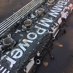
Collection_165. ETK_64_Heating and air conditioning. (part 11) Condenser, fan.
The story of how I searched for and broke fans.
So, I return again to the installation of the parts of the air conditioner, namely - the condenser and the fan. I'll start with the fan.
The air conditioner included a 7-blade fan made by the Canadian manufacturer Power Motion.
The condition is unknown, the appearance is so-so...


The first check showed that it was not working.
Another type of fan was available for the E30 - with 5 blades, made by the German manufacturer Bosch. They are more common on earlier cars. I read somewhere that they are more reliable and easier to repair. Now I can say that this is not so - there is no fundamental difference between them, except for the different design of the impeller and the number of blades on it. But then I decided to look for a Bosch fan, and surprisingly, I found it quite quickly. According to the seller - "it was working".... Its appearance did not inspire much hope either, but I still bought it.


It turned out that it was from a restyling car, and had a different connector, with flat contacts. But this is not a problem. And the problem is that it did not work at all!
Well, what! Now I have both types of fans and both are not working!
The impeller did not want to come off the axis, so I unscrewed three nuts on the back side and thus "through the ass" disassembled it! It was a mistake.
The "brushes" were stuck in it due to dirt, so it did not work. Cleaned the brushes, sanded and painted the body.

The magnets did not hold well, the insulation was almost completely peeled off. I cut the insulation from the same material, glued and installed the magnets in the case.


I wanted to replace the bearing, but the impeller sits dead on the rotor axis and does not want to come off!

When I tried to knock out the axle, I even riveted the thread a little... Now the nut does not tighten. By the way, there is a left thread!

I decided to assemble it just like that, without replacing the bearing. Painted the impeller, and then my mistake caught up with me. With the impeller, there is no access to the bolt heads to lock them and screw the motor to the fan housing!

No matter how hard I tried, it was in vain, because it was impossible to insert the bolts into the holes and fix them to tighten the nuts. Fiasco! ) It would be correct to first remove the impeller, and then disassemble the motor. And then collect in the reverse order. Now I know it! ;)
I put everything in a box and went to look for fans in a flea market again! )) Found, but from E34. I looked at ETK - there they say that they are the same for E30, E32, E34. OK, I'll take it!

I check - it works! But only at the second (maximum) speed. The resistor does not work. And that's just a trifle!... I put it in the same box and put it off for "later". Later, in a flea market, I saw another identical fan from an E34. I bought it - there will be a spare! ;)


It has no resistor at all, so it also works only at maximum speed and the bearing hums a lot. I gladly put it in the same box and put it away again for "later"!
And now "then" has come!

For E30, the diameter is 38 cm

For E34, the diameter is 41 cm

And ETK didn't tell me anything about it! ))) It was not necessary to trust her! )
Well, hope dies last...let's try it on...
First the fan for the E30

From above it becomes almost close to the body

From below, it becomes very tight between the body and the oil cooler

Now the fan for the E34
It does not fit at all from the top

If inserted from above, the oil radiator interferes.

Without the oil cooler, maybe it would fit if you redo the mounts for it. But this is not my option. Again a fiasco! Even double! ))
I remember my very first fan from the set.
I remember my very first fan from the set.
As it turned out, the problem was in the wiring and the resistor. Repaired the wiring, bought a new resistor, cleaned everything.

I check - it works, but only at maximum speed, and with a very strong crackle and crunch. Even with a new resistor, the first speed does not work, the resistor instantly heats up like an iron! I understand that it will not work like this for a long time, or the car will burn down.
Sorted it out. Well, how did I take it apart... broke the hell out of it!

Here, too, the impeller was not removed from the rotor axis. I had to knock it out with a hammer. I tried to beat carefully, but as a result - a cracked impeller

Broken rotor

Broken "brush" housing

The problem was that due to corrosion, the magnets fell away from the housing, rotated together with the rotor and jammed it.


And again I go to look for fans in a flea market! )))) Now only with a diameter of 38 cm)
Although I am lucky in my search! )) Found a fan for E30, again, according to the seller - "it was working"

And still working! Of course, only at maximum speed. And the bearing hums. The resistor does not work.

And here it just farted again! )) A friend gave me his old fan - exactly the same as the one I broke. But he is also already broken.

The resistor does not work - I'm already used to it!

Took both! )

I now have four fans for the E30! And two more for E34)

I did not disassemble the first one correctly, restored it a little, but now I cannot assemble it.

I broke the second one... )

The third one was already broken... ))

The fourth works, but needs repair... I'm already afraid to touch it!... )))

But, "you don't go to the forest to be afraid of wolves!" (c)
Next will be...
P.S.
From my now extensive experience, the main causes of fan failure are:
1. Resistor burned out, works only at maximum speed. Probably so in the majority. I have all six of them.
2. The bearing hums, over time it can jam. The bearing is no longer lubricated from old age or from dirt. Probably also in the majority.
3. Magnets fell off due to corrosion. Loud noise and crackling when working. Can jam.
4. The "brushes" got jammed from dirt. Doesn't work at all.
5. Corrosion of terminals or wires. Doesn't work at all.