After much faffing and procrastination, and because I'm booked on a MLR day at Castle Combe and will thus be mixing with loads of bloody Evos....
It's Turbo Time!
As posted above, I bought an eBay turbo manifold etc. a couple of years back. Didn't fit it because ... well, because it didn't fit.
Cutting the flange between runners just about let me force it onto the head, but it wasn't doing the studs any good and at least one flange section couldn't be pulled flat. So I kind of lost interest...
Until last weekend, when I decided I wasn't going to be beaten by a lump of poorly-made stainless Chinesium and resolved to sort the damn thing out properly.
The first question - why doesn't it fit?
A long time ago, in a design studio far, far away (Munich), someone at BMW decided that the correct bore spacing for a six-cylinder engine was 91mm. Why? Who knows, but damn near every six-pot they've made since the M20 has had its bore centres 91mm apart. And hence its exhaust ports are 91mm apart. As are the exhaust port studs.
Maybe the Chinese have difficulty telling a 1 from a 0, or maybe they just didn't think it would matter, but the spacings on my eBay special were accurate, consistent, and, at 90mm, wrong.
Now some people have mentioned problems fitting these manifolds, and have resorted to drilling the stud holes out to 13mm. I didn't want to do this partly because it would lead to misalignment of the head ports and flange holes (fnarr) and partly because I don't have a 13mm drill bit that can handle stainless.
So here's what I did.
I started by carefully measuring a spare head, to get the exact stud spacing. If you're interested, the vertical spacing, between the top and bottom rows, is 49mm, and the top row is 36mm rightward of the bottom. I then made up a jig, with plain studs 10mm in diameter tightly fitted into a bit of heavy box section, then welded on the reverse side. After cutting the flange between each port, I forced it onto the jig, clamped it down flush, and welded it back together. The flange section for #1 cylinder couldn't be clamped flat against the jig until its runner had been blowtorched orange for a few minutes, allowing it to stretch a bit. I then prised the manifold off the jig and welded up the slots in the flange face. After a clean up with grinder and a flap disc, it looks like this :

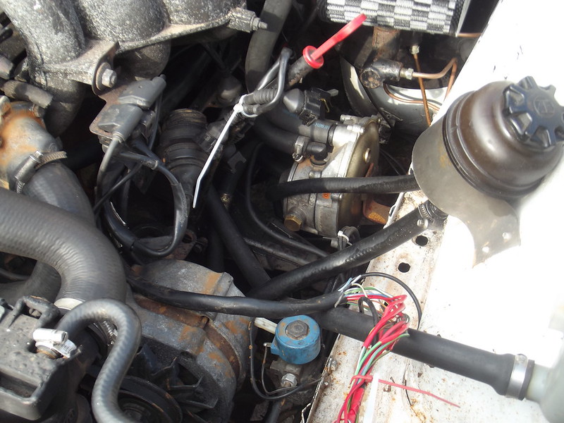
Now it slips on to the head as easily as the OE manifold. Or it would, if it weren't for the oil cooler pipes :

Someone suggested turning the oil filter mount round, but that seems to make things worse :


I noticed that the pipes
almost fitted through the manifold with the filter in the OE position, so after a bit more blowtorch work and pipe bending, and cutting the locating tabs off the oil filter mount to let it swivel further, this happened :

I'm not delighted about the pipe routing; they're both within 10mm of the collector, which will get seriously hot in use. I'll look into some kind of thermal insulation, particularly for the rubber sections.
Now I just need to mount the turbo, run its oil lines, mount the intercooler, fit the coldside plumbing, modify the vaporiser, mount and fit the boost gauge, make up a downpipe...
Oh, and get it dyno'd at some point. Not so much for power, but because I have no idea what the AFRs are now, never mind with a few pounds of boost.