
Hi, today my m50'ed moredoor ''overheated'', the needle crept toward the 3/4 mark, I kept an eye on it and went out to see if the electric fan kicked in. It did not. I started tugging at wires and as soon as I moved the temp switch wiring the fan kicked in. I removed the switch to realize the wires have been screwed/unscrewed in along with the switch when I had my radiator replaced 3 months ago, they were all broken and the connectors just fell out.
So I ordered a new switch as the pins were mangled a bit and I'm wondering what is the way to wire it. There are 3 pins. T1, unmarked and T2. I presume T1 is 80 degree but do I send the power to the middle unmarked pin or the T1 pin? Also what can I use to connect the wires solidly to the pins?
I haven't had a chance to look at the previous wiring as it literally just fell out and the needle like connectors looked flimsy.
Thanks!!
80/88 temp switch trouble
Moderator: martauto
-
JF008
- E30 Zone Regular

- Posts: 631
- Joined: Tue Jan 17, 2012 11:00 pm
- Location: Fort McMurray
I found the connector I need on real oem : ) What a dodgy setup it had! Just need to know which of the 3 pins gets the power.
Happy x max eve's morning
Happy x max eve's morning
-
kam-325i
- E30 Zone Team Member

- Posts: 4851
- Joined: Tue Sep 27, 2005 11:00 pm
- Location: TELFORD !!!! (Shropshire) Stevetigger Land !!!
Common sense would say that the unmarked pin gets the 12v supply, that will be switched to T1 output at temp1, then switched to T2 output at temp2.....
But I would think that the temp switch would drive a relay to switch on the fan, and not power the fan directly....
have you got a P/N for the temp switch, I may be able to find a circuit diagram.
But I would think that the temp switch would drive a relay to switch on the fan, and not power the fan directly....
have you got a P/N for the temp switch, I may be able to find a circuit diagram.
Pete don't care about colour, He would shag a rainbow if he could find the end of it....

-
JF008
- E30 Zone Regular
- Posts: 631
- Joined: Tue Jan 17, 2012 11:00 pm
- Location: Fort McMurray
The wiring is all good with relay etc. I was missing the 3 hole connector to plug to the temp switch, now ordered. I will feed the power to the middle pin as you made it obvious that's where it has to go! Thanks Kam.
No. 15 is the connector I was missing
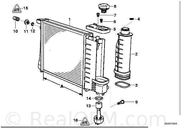
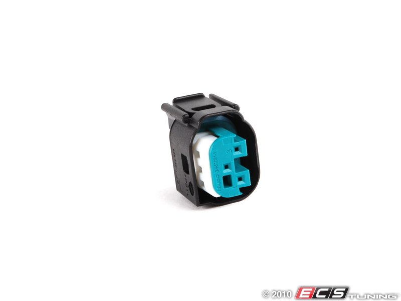
No. 15 is the connector I was missing
-
JF008
- E30 Zone Regular
- Posts: 631
- Joined: Tue Jan 17, 2012 11:00 pm
- Location: Fort McMurray
So now the connector is built, all new parts received. I'm wondering if its safe to connect the 80* side only and not bother with the 88* pin. The fan is a 16'' Revotec/Comex and only has one speed.
Could I connect the 80* side only or would bridging both temp together something that would work in case the temperature would go above 88*?
Thanks,
Happy new year,
JF
Could I connect the 80* side only or would bridging both temp together something that would work in case the temperature would go above 88*?
Thanks,
Happy new year,
JF
-
kam-325i
- E30 Zone Team Member
- Posts: 4851
- Joined: Tue Sep 27, 2005 11:00 pm
- Location: TELFORD !!!! (Shropshire) Stevetigger Land !!!
without seeing a diagram for the switch, I would not know if the 80 side is still switched when the 88 is also on...
Pete don't care about colour, He would shag a rainbow if he could find the end of it....
-
JF008
- E30 Zone Regular
- Posts: 631
- Joined: Tue Jan 17, 2012 11:00 pm
- Location: Fort McMurray
Ok so turns out my existing fan wiring is garbage, runs on an external fuse thing and is generally of bad taste. I have collected the parts I need to wire it according to the wiki.

So I just want to make sure I understand this diagram correctly and that the diagram itself is correct.
To run a single speed electric fan:
- Connect power from fuse 19 (7.5amp) to temp switch inlet
- Connect temp switch outlet (80°) to relay K6 86 pin
- Connect K6 pin 85 to ground
- Connect power from fuse 18 (30 amp) to electric fan power inlet
- Connect electric fan power outlet to ground.
Hope its as simple as it looks : )
Cheers,
Jf
So I just want to make sure I understand this diagram correctly and that the diagram itself is correct.
To run a single speed electric fan:
- Connect power from fuse 19 (7.5amp) to temp switch inlet
- Connect temp switch outlet (80°) to relay K6 86 pin
- Connect K6 pin 85 to ground
- Connect power from fuse 18 (30 amp) to electric fan power inlet
- Connect electric fan power outlet to ground.
Hope its as simple as it looks : )
Cheers,
Jf
-
Brianmoooore

- E30 Zone Team Member
- Posts: 49360
- Joined: Mon Jan 10, 2005 11:00 pm
Slightly easier than that - K6 pin 85 is already connected to ground.
You could also use the purple wiring instead, connected to the correct 'stat pin and less the resistor of course, not that there is any advantage or disadvantage in doing so.
Use a fuse rating (18 ) suitable for the particular fan you are using.
There is a rubber nipple on the side of the fusebox nearest the inner wing. Cut the end off of this, and feed your newly made loom through it. Fan motor earthing point is near the front of the LH inner wing, which the loom will run right by.
You could also use the purple wiring instead, connected to the correct 'stat pin and less the resistor of course, not that there is any advantage or disadvantage in doing so.
Use a fuse rating (18 ) suitable for the particular fan you are using.
There is a rubber nipple on the side of the fusebox nearest the inner wing. Cut the end off of this, and feed your newly made loom through it. Fan motor earthing point is near the front of the LH inner wing, which the loom will run right by.
-
JF008
- E30 Zone Regular
- Posts: 631
- Joined: Tue Jan 17, 2012 11:00 pm
- Location: Fort McMurray
Thank you Brianmoooore, most helpful, now I can tackle this with confidence.
-
JF008
- E30 Zone Regular
- Posts: 631
- Joined: Tue Jan 17, 2012 11:00 pm
- Location: Fort McMurray
So I've worked on this today but had the wrong fuse connectors  Anyhow, as fuse 19 is busy looking after the electric mirrors, can I power the temp switch input via fuse 3 using the orange diagram above? everything else would remain the same.
Also if anyone could post a link to the right fuse connector thing it would be useful. I tried using a locking 4.8mm female spade connector but although it a perfect fit to a fuse it seem to thick for the hole.
Thanks,
JF
Anyhow, as fuse 19 is busy looking after the electric mirrors, can I power the temp switch input via fuse 3 using the orange diagram above? everything else would remain the same.Also if anyone could post a link to the right fuse connector thing it would be useful. I tried using a locking 4.8mm female spade connector but although it a perfect fit to a fuse it seem to thick for the hole.
Thanks,
JF
Last edited by JF008 on Sat Jan 24, 2015 7:07 pm, edited 1 time in total.
-
JF008
- E30 Zone Regular
- Posts: 631
- Joined: Tue Jan 17, 2012 11:00 pm
- Location: Fort McMurray

-
Brianmoooore
- E30 Zone Team Member
- Posts: 49360
- Joined: Mon Jan 10, 2005 11:00 pm
Fuse 19 should be used, since it's ignition switched live and controlled by one of the unloader relays. Splice into the green/black wire inside the fusebox.
Can't help you with part numbers for terminals. I'm far too tight to buy new, and always recycle from scrap fuseboxes.
Can't help you with part numbers for terminals. I'm far too tight to buy new, and always recycle from scrap fuseboxes.
-
JF008
- E30 Zone Regular
- Posts: 631
- Joined: Tue Jan 17, 2012 11:00 pm
- Location: Fort McMurray
You mean splice into one of those two little green/black wires that go up to fuse 19? they are tiny and my soldering iron will do nothing but damage in there : ) Do you mean another green black wire?
Thanks for helping!
JF
Thanks for helping!
JF
-
Brianmoooore
- E30 Zone Team Member
- Posts: 49360
- Joined: Mon Jan 10, 2005 11:00 pm
You don't actually have to 'splice' into it. One of the two wires is the connection for the radiator thermoswitch, which ends at a small multipin socket loose inside the fusebox. Find a single pin plug to fit the socket, or cut the green/black from the socket and join it to your new loom.
-
JF008
- E30 Zone Regular
- Posts: 631
- Joined: Tue Jan 17, 2012 11:00 pm
- Location: Fort McMurray
Thanks again Brian, I might get that done by the end of the year now : )