
I'm looking at installing a data logger, so that I can record engine performance. Basic idea is to take a signal from each wire that feeds the instrument cluster, and converting those signals (resistances) into voltages.
I've identified each wire I need (fuel level, fuel rate, engine speed etc) but the issue is that when the circuits are live I can't get a valid reading because those wires are "in use", as it were.
Is there any way of tapping into those wires without affecting the working of the instrument cluster?
Tapping into instrument wires
Moderator: martauto
-
Grrrmachine
- E30 Zone Wiki / Team Member

- Posts: 8043
- Joined: Sat Feb 09, 2008 11:00 pm
- Location: Warsaw, Poland
'89 325i Touring | Touring Resto Thread | In-Dash Screen install
-
milescook
- E30 Zone Camper

- Posts: 1285
- Joined: Thu Jan 13, 2011 11:00 pm
- Location: The 'bran of Cwm
Isn't there a spare connection that goes to the OBC if you aren't already using it? Could be of use?
The story so far... http://www.cookracing.co.uk/
Also please help the race budget by watching some videos https://www.youtube.com/cookracinguk
Also please help the race budget by watching some videos
https://www.youtube.com/cookracinguk-
Grrrmachine
- E30 Zone Wiki / Team Member
- Posts: 8043
- Joined: Sat Feb 09, 2008 11:00 pm
- Location: Warsaw, Poland
For some of this stuff, that's what I'm using. But for the fuel level, for example; if I put the wire through a multimeter, I get 60 ohms (half a tank). Soon as I switch the ignition on, the meter goes to infinite resistance.
'89 325i Touring | Touring Resto Thread | In-Dash Screen install
-
Speedtouch
- Old Skooler

- Posts: 14124
- Joined: Tue Feb 14, 2006 11:00 pm
- Location: Canterbury
You'll probably need 'buffers' (amplifiers) to take the signal from the instruments with a high impedance input so that they place very little load on them, and give an output corresponding to the varying levels.
You generally use operational amplifiers to do this, e.g., the 741 op-amp, though individual transistors can also be used:
http://www.eecs.tufts.edu/~dsculley/tut ... amps5.html
http://www.muzique.com/lab/buffers.htm
You generally use operational amplifiers to do this, e.g., the 741 op-amp, though individual transistors can also be used:
http://www.eecs.tufts.edu/~dsculley/tut ... amps5.html
http://www.muzique.com/lab/buffers.htm
///M aurice
ECU Upgrade EPROM Chips, £40 posted within the UK. Note these are not Zone chips.
viewtopic.php?f=6&t=279421
ECU Upgrade EPROM Chips, £40 posted within the UK. Note these are not Zone chips.
viewtopic.php?f=6&t=279421
-
Grrrmachine
- E30 Zone Wiki / Team Member
- Posts: 8043
- Joined: Sat Feb 09, 2008 11:00 pm
- Location: Warsaw, Poland
Interesting; I was planning on just making an voltage divider for each signal, as my input board accept inputs of 0-3.3V. I've also got some frequency-to-voltage converters since things like tacho signal will be a pulse rather than a voltage, but I've not experimented with those yet.
'89 325i Touring | Touring Resto Thread | In-Dash Screen install
-
Speedtouch
- Old Skooler
- Posts: 14124
- Joined: Tue Feb 14, 2006 11:00 pm
- Location: Canterbury
Your input board may already have buffers built in, in which case, you can probably get away with feeding in the signals via a current-limiting resistor.
///M aurice
ECU Upgrade EPROM Chips, £40 posted within the UK. Note these are not Zone chips.
viewtopic.php?f=6&t=279421
ECU Upgrade EPROM Chips, £40 posted within the UK. Note these are not Zone chips.
viewtopic.php?f=6&t=279421
-
Brianmoooore

- E30 Zone Team Member
- Posts: 49360
- Joined: Mon Jan 10, 2005 11:00 pm
As Speedtouch has said, it all depends on the source impedance of the signals and the input impedance of your input board. The former needs to much, much lower than the latter, by a few orders of magnitude for analogue signals to avoid affecting the original instrumentation, and for digital signals you just have to be careful not to load the original signal below its 'threshold'. Often digital signals have a much larger amplitude than is apparent, as they are often 'clipped' to a maximum level by a diode connected across them.
There's already a low impedance analogue road speed signal available at most of the pins of the green socket on the instrument cluster, on the underside of the speedo.
Your ohmmeter objects to the signal from the fuel level sensors when you turn the ignition on because the fuel level gauge requires an analogue current signal, not a resistance, and this signal is produced by applying a voltage to the sensors, which your meter objects to an a resistance range. Turn it to a voltage range, and you will get a reading proportional to the amount of fuel in your tank.
-
Grrrmachine
- E30 Zone Wiki / Team Member
- Posts: 8043
- Joined: Sat Feb 09, 2008 11:00 pm
- Location: Warsaw, Poland
Yes, I see what you mean about the signals now - I'm getting voltage through the fuel sender wire, so I'll have to adjust my plans now. The input board accepts 0 to 3.3V and at half a tank, I'm getting 3.6V on my fuel sender wire, so I'll have to find a way to lower that.
The input board is a pretty well made piece of kit, but I don't have any specs about its input impedance unfortunately.
The input board is a pretty well made piece of kit, but I don't have any specs about its input impedance unfortunately.
'89 325i Touring | Touring Resto Thread | In-Dash Screen install
-
Speedtouch
- Old Skooler
- Posts: 14124
- Joined: Tue Feb 14, 2006 11:00 pm
- Location: Canterbury
A simple potential divider circuit made up of resistors, or a potentiometer, will probably suffice to bring the fuel tank sender voltage down to the correct level.
///M aurice
ECU Upgrade EPROM Chips, £40 posted within the UK. Note these are not Zone chips.
viewtopic.php?f=6&t=279421
ECU Upgrade EPROM Chips, £40 posted within the UK. Note these are not Zone chips.
viewtopic.php?f=6&t=279421
-
Grrrmachine
- E30 Zone Wiki / Team Member
- Posts: 8043
- Joined: Sat Feb 09, 2008 11:00 pm
- Location: Warsaw, Poland
Yeah, I'll work it out  I just need to get basic measures of everything first so that I can cobble together an interface board; putting all my potential dividers, F-to-V converters and other resistors in one place, rather than having a labyrinth of loose wires everywhere.
Oil pressure and temp were a peace of cake in comparison.
I just need to get basic measures of everything first so that I can cobble together an interface board; putting all my potential dividers, F-to-V converters and other resistors in one place, rather than having a labyrinth of loose wires everywhere.Oil pressure and temp were a peace of cake in comparison.
'89 325i Touring | Touring Resto Thread | In-Dash Screen install
-
Grrrmachine
- E30 Zone Wiki / Team Member
- Posts: 8043
- Joined: Sat Feb 09, 2008 11:00 pm
- Location: Warsaw, Poland
I've had a few PMs about this, so I'll be keeping this thread updated with my progress for the archives (no point making a Wiki out of such a niche topic).
My aim is to access the coolant temp, tacho signal and fuel level direct from the cluster. Readings change depending on whether you keep the cluster intact (which race-stripped cars may not). That's not my case here, but I'll try and provide both types of data. So:
Tacho cluster signals are voltages. 1000rpm is around 8.5V, 2000 is 7.6V, 3000 is 6.7V and 4000rpm is about 5.8V - therefore a logical scale. No idea what the signal is without the cluster fitted.
Fuel level is a resistance reading from 0 to 120 Ohms, full to empty. The cluster converts to a voltage, so 78 Ohms equates to 3.9volts - I haven't driven enough to calculate how the voltage scales down as resistance drops.
Coolant temp is also a resistance converted to voltage. The trouble is the very narrow range of data; between blue and red on the cluster is a narrow range of resistances, so I'll amend this post with better readings in due course.
All of these signals are converted into compatible voltages via voltage dividers. They are being inputted into a device I bought called a Fusion Brain, which is read via USB onto a standard PC. At the moment the screen looks like this:
'89 325i Touring | Touring Resto Thread | In-Dash Screen install
-
winx
- E30 Zone Camper
- Posts: 1099
- Joined: Wed Jul 30, 2008 11:00 pm
- Location: almost certainly not working on my E30...
Very useful info, I still haven't got round to setting up my digi dash as the car has been off the road for 3 years!
Will be interesting to see what you come up with
Will be interesting to see what you come up with

-
Grrrmachine
- E30 Zone Wiki / Team Member
- Posts: 8043
- Joined: Sat Feb 09, 2008 11:00 pm
- Location: Warsaw, Poland
The only thing I can't work out at the moment is the fuel level. The wire supplying the dash cluster converts to voltage with the ign on, and it seems stable (3.9V) no matter how much fuel is in the tank. I'll have to explore the OBC loom and see if I get different readings, cos I can't get my head round it.
Coolant temp on the other hand is non-linear - resistances start at 4600 ohms for -17 degrees, 1100 ohms is 9 degrees, 275 ohms is 40.5 degrees and 20 ohms is 120 degrees. This is because the area between the blue and red marks of the gauge cover a very small temp area, so the higher resistances don't matter. I'll be ignoring any resistances above 100 ohms (66 degrees) as "too cold", so that I can focus on the sweep from 100 down to 20 ohms.
Coolant temp is linked to the thermostat, so I don't want to equate gauge needle position to any specific temp as various temp thermostats get fitted to these cars, but just in case, 80 degrees is 68 ohms, and 90 degrees is 50 ohms - that way you should be able to use your brown temp sensor to tell which thermostat you have fitted once the engine is up to operating temp
'89 325i Touring | Touring Resto Thread | In-Dash Screen install
-
Grrrmachine
- E30 Zone Wiki / Team Member
- Posts: 8043
- Joined: Sat Feb 09, 2008 11:00 pm
- Location: Warsaw, Poland
The adapter board has now been soldered up, the wiring is all in place and the main screen has been built:

The scales will slide to represent the data, as well as displaying the numerical data for each gauge. At the moment I'm talking to the software developer on conversion formulae so that each input voltage can be converted to bar, celsius or litres, and I need to drive the car around a lot to get base readings for those conversions. But things are very much progressing
The scales will slide to represent the data, as well as displaying the numerical data for each gauge. At the moment I'm talking to the software developer on conversion formulae so that each input voltage can be converted to bar, celsius or litres, and I need to drive the car around a lot to get base readings for those conversions. But things are very much progressing
'89 325i Touring | Touring Resto Thread | In-Dash Screen install
-
Grrrmachine
- E30 Zone Wiki / Team Member
- Posts: 8043
- Joined: Sat Feb 09, 2008 11:00 pm
- Location: Warsaw, Poland
Asked in another thread:
Fuel rate is sent as a frequency (square wave) so you'll need an oscilloscope or a frequency-to-voltage converter to make use of it. I've isolated this wire but not connected it because, well, it has no practical use.gromgsxr wrote:Does anyone know what sorta signal the ecu sends out on the fuel rate wire by any chance would love to get the obc and econometer working properly with a stand alone ecu
'89 325i Touring | Touring Resto Thread | In-Dash Screen install
-
gromgsxr
- E30 Zone Regular

- Posts: 451
- Joined: Tue Dec 06, 2011 11:00 pm
I thought as much if read that it basically pulsed the same as the first bank of injectors and uses the vss as well how many times do the injectors fire on the first bank of cylinders per engine cycle on motronic?
-
gromgsxr
- E30 Zone Regular
- Posts: 451
- Joined: Tue Dec 06, 2011 11:00 pm
OK well its connected up to a injector I'm running sequential injection so that's 1 injection event per engine cycle eg 720° crank rotation and success the little needle that's been dead for months moves and according to the calculated mpg in tunerstudio its correct the within +-2mpg. If that is working in theory the rest of the functions on the obc should function to some extent??
-
Grrrmachine
- E30 Zone Wiki / Team Member
- Posts: 8043
- Joined: Sat Feb 09, 2008 11:00 pm
- Location: Warsaw, Poland
You lost me. What's the question?
'89 325i Touring | Touring Resto Thread | In-Dash Screen install
-
gromgsxr
- E30 Zone Regular
- Posts: 451
- Joined: Tue Dec 06, 2011 11:00 pm
OK i I'm running megasquirt and have connected up and got the econameter working fairly accuatly in theory would the rest of the functions of the obc work to a extent now?
-
Brianmoooore
- E30 Zone Team Member
- Posts: 49360
- Joined: Mon Jan 10, 2005 11:00 pm
If the instrument cluster works fully, then so should the OBC. It takes all its signals, except external temp., direct from the cluster.
-
gromgsxr
- E30 Zone Regular
- Posts: 451
- Joined: Tue Dec 06, 2011 11:00 pm
It does indeed seem to be working fairly well
-
milescook
- E30 Zone Camper
- Posts: 1285
- Joined: Thu Jan 13, 2011 11:00 pm
- Location: The 'bran of Cwm
Hi Grr, how are you getting on? I'm fascinated with playing with data logging, as my car will be hitting the track soon. I want to capture revs (and temps) at least, to combine with GPS data and show me how poor my driving is  Could even take that a stage further and add crude resistance meter devices to track throttle and braking?
I've been thinking about these - http://www.raspberrypi.org/faqs
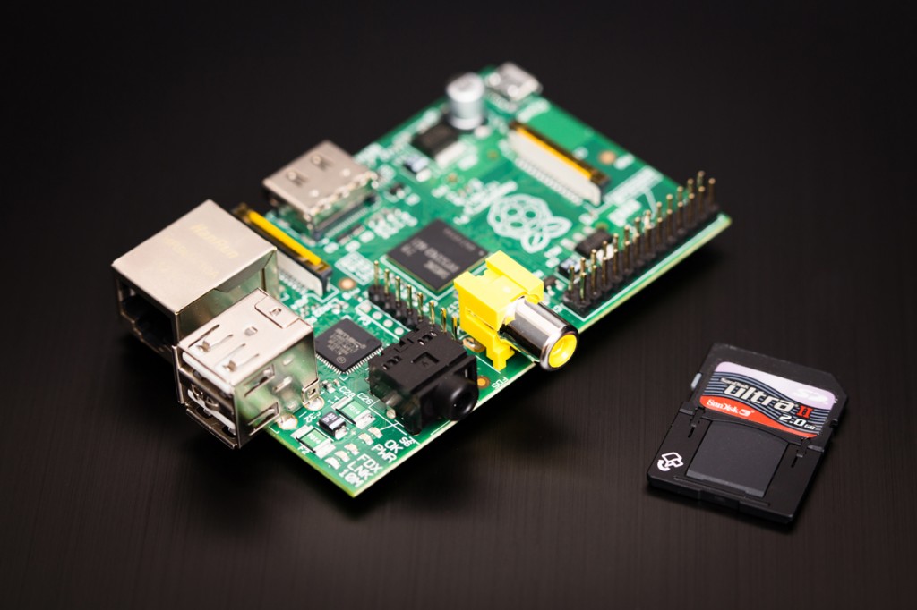
As it's Linux based it would allow me to easily program it in Python to capture inputs, and store in some kind of Logger (I initially thought Motec http://www.motec.com/i2/i2overview/ but it needs a license for CSV import for the Pro version...) friendly format , as it has some input pins:
http://www.cl.cam.ac.uk/projects/raspbe ... _switches/
It can't be hard to fabricate some sort of intercepting plug between the ECU and ECU plug, that feeds data to the device (25 dollars!)?
One practical thing I've noticed with my proposed solution using a pi, is it accepts digital inputs. But,
"Although there is no analogue input, it is possible to simulate a very crude form of analogue input by timing the charging of a capacitor. So if say the capacitor is discharged by the GPIO in output mode then switched to input and the capacitor charged up through the variable resistor then the time to reach the input threshold is shorter when the resistance is smaller. This can be detected by using an interrupt triggered by the pin changing state and you can then convert the time into an analogue value."
and
http://nwazet.com/pi-keylime
I'm dead excited!
Any major technical hurdles I haven't considered? 
Could even take that a stage further and add crude resistance meter devices to track throttle and braking? I've been thinking about these - http://www.raspberrypi.org/faqs
As it's Linux based it would allow me to easily program it in Python to capture inputs, and store in some kind of Logger (I initially thought Motec http://www.motec.com/i2/i2overview/ but it needs a license for CSV import for the Pro version...) friendly format , as it has some input pins:
http://www.cl.cam.ac.uk/projects/raspbe ... _switches/
It can't be hard to fabricate some sort of intercepting plug between the ECU and ECU plug, that feeds data to the device (25 dollars!)?
One practical thing I've noticed with my proposed solution using a pi, is it accepts digital inputs. But,
"Although there is no analogue input, it is possible to simulate a very crude form of analogue input by timing the charging of a capacitor. So if say the capacitor is discharged by the GPIO in output mode then switched to input and the capacitor charged up through the variable resistor then the time to reach the input threshold is shorter when the resistance is smaller. This can be detected by using an interrupt triggered by the pin changing state and you can then convert the time into an analogue value."
and
http://nwazet.com/pi-keylime
I'm dead excited!
Any major technical hurdles I haven't considered? The story so far... http://www.cookracing.co.uk/
Also please help the race budget by watching some videos https://www.youtube.com/cookracinguk
Also please help the race budget by watching some videos
https://www.youtube.com/cookracinguk-
milescook
- E30 Zone Camper
- Posts: 1285
- Joined: Thu Jan 13, 2011 11:00 pm
- Location: The 'bran of Cwm
For added info, the yellow connector on the back of the cluster can give:
Instrument cluster C3
Pin MFC OBC
1 Br Ground from C1-20
2 N/C GnBk Hot in run or start, from fuse 10, out
4 N/C BrGy Low fuel indicator
5 N/C BrGn Fuel tank level sensor
8 BrWt Illumination level -- dimmer to ground
9 N/C Hot in start
10 N/C Hot at all times, via fuse 21
13 Gy/Vi RA12 +12V Hot in Accy, run and start via C2-13 fuse 12 (GnVi)
14 N/C Hot in run or start, from fuse 10
15 N/C Hot in run or start, from fuse 10
20 GyRd Back light on, switch to +12V via C2-23 fuse 23
22 N/C BkYl Hot in start (BkGn?)
23 RdWt Hot at all times, via C1-2 fuse 21 (listed as RdBk)
25 N/C WtBu Present fuel rate, Motronic pin 11(e)/32(i)
26 Br/Rd Speed output
Of course that's dead handy for speed and poss fuel rate, and the fact that the plug socket on mine is now empty is great. But for tempreature and revs I'd still need to tap into the other instrument plug. Would it be easier to intercept the ECU plug or the 2 instrument cluster plugs?
The story so far... http://www.cookracing.co.uk/
Also please help the race budget by watching some videos https://www.youtube.com/cookracinguk
Also please help the race budget by watching some videos
https://www.youtube.com/cookracinguk-
Grrrmachine
- E30 Zone Wiki / Team Member
- Posts: 8043
- Joined: Sat Feb 09, 2008 11:00 pm
- Location: Warsaw, Poland
I tapped the wires behind the instrument cluster since I was back there fiddling with the yellow plug anyway.
I did get my system taking readings, but it's still a long way from being calibrated. I think if you're using the Pi then you're going to have a lot of work playing with capacitors getting reasonable, reliable analogue readings. Are you sure you wouldn't be better off with an Arduino of some sort?
I did get my system taking readings, but it's still a long way from being calibrated. I think if you're using the Pi then you're going to have a lot of work playing with capacitors getting reasonable, reliable analogue readings. Are you sure you wouldn't be better off with an Arduino of some sort?
'89 325i Touring | Touring Resto Thread | In-Dash Screen install
-
milescook
- E30 Zone Camper
- Posts: 1285
- Joined: Thu Jan 13, 2011 11:00 pm
- Location: The 'bran of Cwm
My main driver for using the pi is its a linux os which I can program on and has limitless potential. Wifi, web host to connect via smartphone and configure, gps modules over usb and all sorts of fun.i was looking at potentiometers to connect to the throttle body to take throttle position. All sorts really.
I looked at the arduino it seems better suited out of the box but a pi is cheap and essentially a pc.
I guess the question is how long I would go beforr I got bored and acknowledged that a more embedded aolution is the way to go, I just like the possibilities.
I think I will have a go....ill certainly lwarn something!
The story so far... http://www.cookracing.co.uk/
Also please help the race budget by watching some videos https://www.youtube.com/cookracinguk
Also please help the race budget by watching some videos
https://www.youtube.com/cookracinguk-
milescook
- E30 Zone Camper
- Posts: 1285
- Joined: Thu Jan 13, 2011 11:00 pm
- Location: The 'bran of Cwm
http://www.pcpro.co.uk/features/381787/ ... lternative
Interwstingly in that article the arduino can also bolt onto the pi.
Interwstingly in that article the arduino can also bolt onto the pi.
The story so far... http://www.cookracing.co.uk/
Also please help the race budget by watching some videos https://www.youtube.com/cookracinguk
Also please help the race budget by watching some videos
https://www.youtube.com/cookracinguk