
The DTM mounting point was moved up to the top of the hub however it was still single shear.harry_p wrote:i am sure they would, but the road cars don't have all their rear weight on the one bolt, and yes, dtm cars are going to have a hell of a hard time, but i've yet to see one smash over typical b-road potholes at 100mph. most normal peoples suspension is pretty much fit and forget for thousands of harsh bumpy miles, whilst i expect dtm cars got their major load bearing bolts swapped after every round!
if they had wanted to, would they even have been able to alter the way the damper is mounted within the regulations?
Has anyone strengthened the rear arm using Gaz Coilovers?
Moderator: martauto
-
Jhonno
- Homo Hair
- Posts: 20362
- Joined: Mon Jan 10, 2005 11:00 pm
- Location: FLAT, FLAT, FLAT!!

-
HairyScreech
- Engaged to the E30 Zone

- Posts: 6265
- Joined: Sun Jan 21, 2007 11:00 pm
hmm, even with a 60n/mm spring and 80mm travel we are looking at too much force.
theres 3 issues here.
1. spring rate
2. suspension travel
3. distance from the trailing arm to the centre of the coil over eye mount.
without these 3 we will be speculating.
however assuming a 3" travel and an eye centre 35mm from the arm the max spring before breakage is 49n/mm or 279lb/inch. (assuming an 8.8 grade bolt)
Which means if the spring rates were 40n/mm then they were pretty close to the wind. That bolt would have been doing no more than 1 race!
As i say though with out the values for the 3 things above being right this is only speculation.
The calcs above assume the spacer to the outside of the gaz bottom eye is 25mm and the eye is 20mm, thus placing the centre of the load 35mm from the trailing arm.
If the eye is moved closer to the trailing arm then the bending moment is reduced.
2.8 development thread http://www.e30zone.net/modules.php?name ... c&t=170822
m3.3.1 m20 thread - now running, chip needed - any volunteers?
http://www.e30zone.net/modules.php?name ... =viewtopic&
m3.3.1 m20 thread - now running, chip needed - any volunteers?
http://www.e30zone.net/modules.php?name ... =viewtopic&
-
HairyScreech
- Engaged to the E30 Zone
- Posts: 6265
- Joined: Sun Jan 21, 2007 11:00 pm
if i remember then ill take some measurements of mine tomorrow so we can get a proper answer.
i think want is certain is the bolts are in a situation where fatigue is an issue, its just a question of how bad it is.
i think want is certain is the bolts are in a situation where fatigue is an issue, its just a question of how bad it is.
2.8 development thread http://www.e30zone.net/modules.php?name ... c&t=170822
m3.3.1 m20 thread - now running, chip needed - any volunteers?
http://www.e30zone.net/modules.php?name ... =viewtopic&
m3.3.1 m20 thread - now running, chip needed - any volunteers?
http://www.e30zone.net/modules.php?name ... =viewtopic&
-
f0xy

- E30 Zone Regular

- Posts: 276
- Joined: Mon Oct 04, 2010 11:00 pm
My rear coilovers are off the car at the moment - do you just want the unsprung damper travel? I can get the spring rate off my notes and the distance measurement too.
-
keri-WMS
- E30 Zone Camper

- Posts: 1269
- Joined: Sat Apr 29, 2006 11:00 pm
My understanding is that it's shock (fast) loadings that will carry the highest forces - not springs which carry a fairly smooth/even load.
So increased shock rates will have a bigger effect than adding springs and using a coil-over design...
In most cases adding a spring to a shock-mount is fine, it's adding shocks to spring-mounts that tends to break things.
So increased shock rates will have a bigger effect than adding springs and using a coil-over design...
In most cases adding a spring to a shock-mount is fine, it's adding shocks to spring-mounts that tends to break things.
WMS E30 brake kits! (4-pot 280mm & 300mm front / 2-pot 290mm rear)
www.wms-brakes.co.uk / http://www.e30zone.net/modules.php?name ... c&t=209737
www.wms-brakes.co.uk / http://www.e30zone.net/modules.php?name ... c&t=209737
-
GeoffBob
- Forced Induction Specialist
- Posts: 1843
- Joined: Tue Apr 28, 2009 11:00 pm
I think you'll find that's the yield strength at 80% of UTS in tension Screech. You can expect to see a bolt fail at around half that value in shear.HairyScreech wrote:going at 80% uts as the bolt is stated on the last page as a 8.8 grade.
Thus 800n/mm^2 and 80%
I do believe, however, that if you are concerned with spring deflection then you should be looking to calculate that deflection as a function of the applied load (due to the action of the un-sprung mass upon the sprung mass while riding a defined terrain), and not the other way around. The deflection of the spring is little else other than an indicator of the load applied to the spring (much like a spring type bathroom scale), it does not define it.
I believe that you are correct Keri. It is often forgotten that while a spring resists deflection, a damper resists rate-of-change of deflection. That is to say, the force exerted by a damper is a function of how fast it is being displaced (that really is what defines a damper). A step-change in terrain (such as a curb-stone or pot-hole) results in a significantly greater reaction force from the damper than from the spring.keri-WMS wrote:My understanding is that it's shock (fast) loadings that will carry the highest forces - not springs which carry a fairly smooth/even load.
So increased shock rates will have a bigger effect than adding springs and using a coil-over design...
In most cases adding a spring to a shock-mount is fine, it's adding shocks to spring-mounts that tends to break things.
Despite expecting the bolt to fail in shear at a lower value than indicated by screech, I still would not expect to see that bolt fail. If we assume roughly 230kg of static load over each rear wheel then you’d require a dynamic load of near 15 times that to get that bolt to fail (by my estimation) and near 30 times that by Screech’s. Around a well manicured track I would not expect to see dynamic loads that high.
But honestly gents, that’s just my opinion with some very rough calculations thrown in for measure. I’m not looking for a fight and it certainly is not my intention to diminish your efforts Screech.

"It is amazing how many drivers, even at the Formula-1 level, think that brakes are for slowing the car down." - Mario Andretti
-
Demlotcrew
- E30 Zone Team Member

- Posts: 13329
- Joined: Mon Dec 20, 2004 11:00 pm
- Location: East Anglia
Absolutely, and when you add very high pressure dampers this adds to the load even more.
The point was to see what the spring on its own would do.
I don't know the formulas, but I don't see why the damper travel value would be part of it?
The point was to see what the spring on its own would do.
I don't know the formulas, but I don't see why the damper travel value would be part of it?

-
GeoffBob
- Forced Induction Specialist
- Posts: 1843
- Joined: Tue Apr 28, 2009 11:00 pm
Hi Andrew,Demlotcrew wrote:I don't see why the damper travel value would be part of it?
Not the actual travel, but how fast it is travelling.
If you will, imagine holding a common oil filled damper between both hands. It's relatively easy to compress or extend the damper provided you do it slowly. Try do it at speed and it gets more and more difficult. This is because a damper resists (exerts a force) in response to how fast it is displaced.
HTH
Geoff
"It is amazing how many drivers, even at the Formula-1 level, think that brakes are for slowing the car down." - Mario Andretti
-
HairyScreech
- Engaged to the E30 Zone
- Posts: 6265
- Joined: Sun Jan 21, 2007 11:00 pm
Obviously not geoff, open and clear discussion is the only way to hash these things out properly.
as for the yield yes your right that is in tension, but then the yield doesn't actually factor into anything if you just do the bending and shear stress calculation.
I too have been told the largest force is in the rebound, although with a spring over damper the spring and damper are acting on each other directly with this load never being transmitted to the mounting points.
Which leaves the largest force on the bolt in a coil over application the compressive loading.
Which would certainly follow what i have seen, i have always questioned the damper loading thing, certainly when applied to coil over units as i have only ever seen them broken at the mountings in compression.
We cannot quantify the load spike produced by the damper in compression so all we can do is look at the spring force.
I was after the damper travel as the spring rate is in N/mm or lb/inch, so any spring load needs to be looked at as the rating x the deflection.
Although this may be an over simplification, as that would assume a correctly sprung car to fully absorb highest load, which a track car on coil overs is most certainly not as the spring rates are being used to control pitch.
Perhaps a measurement of the wear mark on the damper might be more helpful at that will tell us how much load is applied during day to day depravity.
We will be better served looking at the load as a function of the damper travel seen in normal use than guessing at a maximum loading.
at least if we times the used damper travel by the spring rate we will have something reasonable go on.
Tbh, none of this has considered bottom out forces, which that bolt is no way able to handle, one trip up the mountain at Cadwell or over the curbs and the compression spike is potentially massive.
Again if it was me i would still be running the bottomout bump stops on the trailing arm pad, where they were originally.
For illustration our formula renault a 540kg race car bent a 10mm axially loaded pushrod adjuster the other week after a bit of a corner cut and the curbs at pembrey are no way near the suspension smashers at some tracks.
ill drag milliken and milliken out in a bit and see if they have anything to say on the subject.
2.8 development thread http://www.e30zone.net/modules.php?name ... c&t=170822
m3.3.1 m20 thread - now running, chip needed - any volunteers?
http://www.e30zone.net/modules.php?name ... =viewtopic&
m3.3.1 m20 thread - now running, chip needed - any volunteers?
http://www.e30zone.net/modules.php?name ... =viewtopic&
-
HairyScreech
- Engaged to the E30 Zone
- Posts: 6265
- Joined: Sun Jan 21, 2007 11:00 pm
100%, the only trouble is i certainly have no idea how high this high speed compression force is and certainly it will vary between dampers.GeoffBob wrote:Hi Andrew,Demlotcrew wrote:I don't see why the damper travel value would be part of it?
Not the actual travel, but how fast it is travelling.
If you will, imagine holding a common oil filled damper between both hands. It's relatively easy to compress or extend the damper provided you do it slowly. Try do it at speed and it gets more and more difficult. This is because a damper resists (exerts a force) in response to how fast it is displaced.
HTH
Geoff
Without putting it on a damper dyno i think we can only acknowledge its presence and say that its an as well as force ontop of what the springs resist.
certainly if its going to be a 1 hit fail then the damping will be the culprit, but if the bolt is going to fatigue under normal spring loadings then its still going to be best to either put it into double shear or periodically replace them.
2.8 development thread http://www.e30zone.net/modules.php?name ... c&t=170822
m3.3.1 m20 thread - now running, chip needed - any volunteers?
http://www.e30zone.net/modules.php?name ... =viewtopic&
m3.3.1 m20 thread - now running, chip needed - any volunteers?
http://www.e30zone.net/modules.php?name ... =viewtopic&
-
HairyScreech
- Engaged to the E30 Zone
- Posts: 6265
- Joined: Sun Jan 21, 2007 11:00 pm
Ok, i have just measured my "normal" damper mount on the car, its 20mm to the center line of the eye.
However there is a 14mm tube that the rubber damper bush is centered on.
This 14mm tube will take some of the bending load.
Do the GAZ dampers have a mounting tube or are they direct to the bolt?
Do the sleeves either side of the eye mount hold the rose joint tight?
If so a simple bending and shear analysis wont be enough, and frankly that's deeper than i know how to go and gets pretty damn complicated quickly.
What i could do if that's the case is get some higher help that may be able to give an answer.
2.8 development thread http://www.e30zone.net/modules.php?name ... c&t=170822
m3.3.1 m20 thread - now running, chip needed - any volunteers?
http://www.e30zone.net/modules.php?name ... =viewtopic&
m3.3.1 m20 thread - now running, chip needed - any volunteers?
http://www.e30zone.net/modules.php?name ... =viewtopic&
-
keri-WMS
- E30 Zone Camper
- Posts: 1269
- Joined: Sat Apr 29, 2006 11:00 pm
In simple terms again... 
Isn't there a balljoint/bush on the bottom of the shock, and the bolt holds that against the arm?
In which case, as long as the bolt is torqued correctly (and that torque is high enough), the load travels from wheel > hub > bearing > arm > inside of bush/balljoint > outside of bush/balljoint and into the shock body and bypasses the bolt? So there are no side forces on the bolt as long as it's tight enough - ie as long as the shock force doesn't overcome the friction on the bush>arm mating surfaces?
EDIT - Almost the same point as the last post, a few seconds too slow by me!
WMS E30 brake kits! (4-pot 280mm & 300mm front / 2-pot 290mm rear)
www.wms-brakes.co.uk / http://www.e30zone.net/modules.php?name ... c&t=209737
www.wms-brakes.co.uk / http://www.e30zone.net/modules.php?name ... c&t=209737
-
HairyScreech
- Engaged to the E30 Zone
- Posts: 6265
- Joined: Sun Jan 21, 2007 11:00 pm
yes, thats what im trying to establish, is there a series of spacers or a tube that goes over the bolt which is then torqued against the arm?
Even in the case of the gaz damper?
Normal dampers obviously have a tube that the bolt goes through as the rubber needs to be mounted to something.
The effect of the bolt crushing down on this tube makes it effectively become a 15mm stub.
Which lets face it will take the damper loads of a road set up no worries.
However it looks like the gaz eye runs direct on the bolt with spacers either side, i assume the bolt clamps the spacer tightly up to the rose joints eye.
In which case i'm not sure how to work that out, i don't know if that's a simple load case or not.
I'm due in for a meeting at 12 and i shall badger the motorcycle engineering guy, he is both a dynamics lecturer and a doctor of physics.
2.8 development thread http://www.e30zone.net/modules.php?name ... c&t=170822
m3.3.1 m20 thread - now running, chip needed - any volunteers?
http://www.e30zone.net/modules.php?name ... =viewtopic&
m3.3.1 m20 thread - now running, chip needed - any volunteers?
http://www.e30zone.net/modules.php?name ... =viewtopic&
-
Jhonno
- Homo Hair
- Posts: 20362
- Joined: Mon Jan 10, 2005 11:00 pm
- Location: FLAT, FLAT, FLAT!!
My Intrax rear coilovers have a nylon bush iirc, which the bolt goes through and tightens up to.
-
GeoffBob
- Forced Induction Specialist
- Posts: 1843
- Joined: Tue Apr 28, 2009 11:00 pm
TaHairyScreech wrote:Obviously not geoff, open and clear discussion is the only way to hash these things out properly.
I understand what you mean Screech, but I had in mind though that the yield stress in shear was roughly half that of the yield stress in tension (as stamped on the bolt head). Well, actually 1/sqrt(3) = 0.577, but a half is close enough for me. Has to do with the Von Mises something or other (that relates tensile strength to shear strength) as I recall.HairyScreech wrote:as for the yield yes your right that is in tension, but then the yield doesn't actually factor into anything if you just do the bending and shear stress calculation.
Wasn’t specifically considering either bump or rebound TBH, was just considering/speculating the maximum shear load to which that bolt might be exposed in the course of normal duty.HairyScreech wrote:I too have been told the largest force is in the rebound, although with a spring over damper the spring and damper are acting on each other directly with this load never being transmitted to the mounting points.
I can live with that Screech. I accept that the bolt under discussion could indeed suffer dire consequences if hammered hard enough.HairyScreech wrote:Tbh, none of this has considered bottom out forces, which that bolt is no way able to handle, one trip up the mountain at Cadwell or over the curbs and the compression spike is potentially massive. Again if it was me i would still be running the bottomout bump stops on the trailing arm pad, where they were originally.
For illustration our formula renault a 540kg race car bent a 10mm axially loaded pushrod adjuster the other week after a bit of a corner cut and the curbs at pembrey are no way near the suspension smashers at some tracks.
"It is amazing how many drivers, even at the Formula-1 level, think that brakes are for slowing the car down." - Mario Andretti
-
Demlotcrew
- E30 Zone Team Member
- Posts: 13329
- Joined: Mon Dec 20, 2004 11:00 pm
- Location: East Anglia
My coilovers use a series of steel selves which clamp the rose joint from both sides and they also sleeve in to the rose joint it self and I have also made a step in to the arm and then machined one of the sleeves to fit inside this step in the arm, very much like a dowel in a cylinder head.HairyScreech wrote:yes, thats what im trying to establish, is there a series of spacers or a tube that goes over the bolt which is then torqued against the arm?
Even in the case of the gaz damper?
Normal dampers obviously have a tube that the bolt goes through as the rubber needs to be mounted to something.
The effect of the bolt crushing down on this tube makes it effectively become a 15mm stub.
Which lets face it will take the damper loads of a road set up no worries.
However it looks like the gaz eye runs direct on the bolt with spacers either side, i assume the bolt clamps the spacer tightly up to the rose joints eye.
In which case i'm not sure how to work that out, i don't know if that's a simple load case or not.
I'm due in for a meeting at 12 and i shall badger the motorcycle engineering guy, he is both a dynamics lecturer and a doctor of physics.
The reason i did this was because the E30 bolts are NLA from BMW and i had to use a slightly shorter one from an E36, plus it added a little more support for the bolt., the step is only 3mm in.
-
HairyScreech
- Engaged to the E30 Zone
- Posts: 6265
- Joined: Sun Jan 21, 2007 11:00 pm
That's actually a very good way to go about it.Demlotcrew wrote:My coilovers use a series of steel selves which clamp the rose joint from both sides and they also sleeve in to the rose joint it self and I have also made a step in to the arm and then machined one of the sleeves to fit inside this step in the arm, very much like a dowel in a cylinder head.HairyScreech wrote:yes, thats what im trying to establish, is there a series of spacers or a tube that goes over the bolt which is then torqued against the arm?
Even in the case of the gaz damper?
Normal dampers obviously have a tube that the bolt goes through as the rubber needs to be mounted to something.
The effect of the bolt crushing down on this tube makes it effectively become a 15mm stub.
Which lets face it will take the damper loads of a road set up no worries.
However it looks like the gaz eye runs direct on the bolt with spacers either side, i assume the bolt clamps the spacer tightly up to the rose joints eye.
In which case i'm not sure how to work that out, i don't know if that's a simple load case or not.
I'm due in for a meeting at 12 and i shall badger the motorcycle engineering guy, he is both a dynamics lecturer and a doctor of physics.
The reason i did this was because the E30 bolts are NLA from BMW and i had to use a slightly shorter one from an E36, plus it added a little more support for the bolt., the step is only 3mm in.
and yes etk says the bolts are the same but the e36 one is 3mm shorter.
Which does make me wonder if it is just a normal bolt that can be obtained in the right grade from anywhere.
i checked up, we need to treat the thing as a whole.
Basically where its has spacers we can just treat it as one solid steel bolt the same diameter as the outer diameter of the sleeves.
Which is what i was thinking and as long as the bolt is correctly torqued then it will behave as a solid piece for all intents and purposes.
So assuming the spacers are about 2mm thick we can just treat it as a bolt 16mm in diameter and the answer produced will be close enough to make no odds. (the thinking being if your close enough to the max stress that the error introduced matters then your either in f1 and should be using fea or its time to fit a bigger bolt anyway.)
2.8 development thread http://www.e30zone.net/modules.php?name ... c&t=170822
m3.3.1 m20 thread - now running, chip needed - any volunteers?
http://www.e30zone.net/modules.php?name ... =viewtopic&
m3.3.1 m20 thread - now running, chip needed - any volunteers?
http://www.e30zone.net/modules.php?name ... =viewtopic&
-
Demlotcrew
- E30 Zone Team Member
- Posts: 13329
- Joined: Mon Dec 20, 2004 11:00 pm
- Location: East Anglia
The bolt has a shoulder on it and that is very specific, you could get a blank M13 and have it machined down and then case hardened to the the correct grade.
-
HairyScreech
- Engaged to the E30 Zone
- Posts: 6265
- Joined: Sun Jan 21, 2007 11:00 pm
I have an e36 rear end by the back door (uber council i know) so ill have a look, never really looked at the bolt that close as you wouldn't really unless you were going to replace it or check it like this.
i have assumed 16mm outer diameter for the spacers here (ignore where is wrote 14mm at the start, i wrote that while at uni)
If someone would like to check the math (as i'm prone to stupid errors) then we can assume this is the acceptable minimum loading for failure and fatigue to occur.
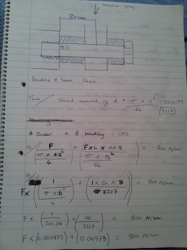
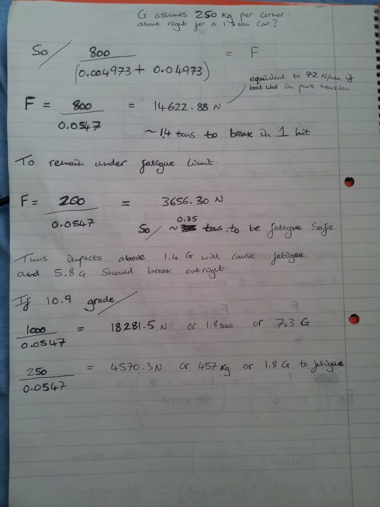
Thought i would just do it as maximum safe wheel loads, then once we know the spring rate we can see if its above or below.
Pretty much from that we can see it doesn't take much to produce a fatigue effect in the bolt.
Its 100% a bolt i would be replacing at least yearly if i was going to rely on it to hold the car up and i think that's a small concession given the consequence of it failing.
i have assumed 16mm outer diameter for the spacers here (ignore where is wrote 14mm at the start, i wrote that while at uni)
If someone would like to check the math (as i'm prone to stupid errors) then we can assume this is the acceptable minimum loading for failure and fatigue to occur.
Thought i would just do it as maximum safe wheel loads, then once we know the spring rate we can see if its above or below.
Pretty much from that we can see it doesn't take much to produce a fatigue effect in the bolt.
Its 100% a bolt i would be replacing at least yearly if i was going to rely on it to hold the car up and i think that's a small concession given the consequence of it failing.
2.8 development thread http://www.e30zone.net/modules.php?name ... c&t=170822
m3.3.1 m20 thread - now running, chip needed - any volunteers?
http://www.e30zone.net/modules.php?name ... =viewtopic&
m3.3.1 m20 thread - now running, chip needed - any volunteers?
http://www.e30zone.net/modules.php?name ... =viewtopic&
-
GeoffBob
- Forced Induction Specialist
- Posts: 1843
- Joined: Tue Apr 28, 2009 11:00 pm
Been a while since I worked out shear and bending moment diagrams on beams, but I follow your working OK Screech.
I see, however, that you are equating the sum of the shear and bending stress to the UTS of the material. The shear stress (on the left) is the usual applied force divided by the cross-sectional area of the beam, while the bending stress on the right is the bending moment (force x distance) divided by the section modulus, where the section modulus is by definition the 2nd moment of area divided by the maximum distance from the centroid of the beam (which is, in this case, the radius). So all good so far.
Only thing is, the bending stress determined by the right hand term is in a direction parallel to the axis of the beam. It's at 90 degrees to the shear stress, so you can't simply add the two directly to each other. Think of a cantilever beam jutting out from the side of a wall. The force applied to the end of the beam (pushing it down) tends to tear the beam out at the top edge where it connects to the wall, but push it in at the bottom edge of the wall. Top edge is in tension, bottom edge is in compression ”“ the bending stresses run parallel to the neutral axis while the shear stress is parallel to the wall.
Not that it makes a huge difference, mind you, as the bending stress clearly dominates (by an order of magnitude) over the shear stress. So, as I think you have clearly demonstrated, if the bolt is to fail it will be as a result of bending, and at an uncomfortably low value as well. Good on you since I initially only considered the shear stress.
Considering the bending stress only (ignoring shear) it works out (using exactly your values above) to a static weight of 1.6ton required to break that bolt. That’s a bit too low for comfort in my opinion.
It’s also worth keeping in mind that the bolt plus spacer only behave as a 16mm diameter beam so long as the tensile force in the bolt (after tightening it up) compresses the spacer between the bolt head and the shoulder of the mounting hole. If that bolt were to come loose that spacer would simply be along for the ride and you can treat that bolt as a 12mm diameter beam, which would bend and fail under a static load of only 680kg (again ignoring the shear stress).
I think you were right to do this calculation Screech. Well done . I retract my statement about bouncing the car around on one wheel to get that bolt to break, I was wrong. That bolt genuinely is a weak point, particularly if it were ever to come loose. At the very least a 10.8 grade bolt should be fitted.
I see, however, that you are equating the sum of the shear and bending stress to the UTS of the material. The shear stress (on the left) is the usual applied force divided by the cross-sectional area of the beam, while the bending stress on the right is the bending moment (force x distance) divided by the section modulus, where the section modulus is by definition the 2nd moment of area divided by the maximum distance from the centroid of the beam (which is, in this case, the radius). So all good so far.
Only thing is, the bending stress determined by the right hand term is in a direction parallel to the axis of the beam. It's at 90 degrees to the shear stress, so you can't simply add the two directly to each other. Think of a cantilever beam jutting out from the side of a wall. The force applied to the end of the beam (pushing it down) tends to tear the beam out at the top edge where it connects to the wall, but push it in at the bottom edge of the wall. Top edge is in tension, bottom edge is in compression ”“ the bending stresses run parallel to the neutral axis while the shear stress is parallel to the wall.
Not that it makes a huge difference, mind you, as the bending stress clearly dominates (by an order of magnitude) over the shear stress. So, as I think you have clearly demonstrated, if the bolt is to fail it will be as a result of bending, and at an uncomfortably low value as well. Good on you since I initially only considered the shear stress.
Considering the bending stress only (ignoring shear) it works out (using exactly your values above) to a static weight of 1.6ton required to break that bolt. That’s a bit too low for comfort in my opinion.
It’s also worth keeping in mind that the bolt plus spacer only behave as a 16mm diameter beam so long as the tensile force in the bolt (after tightening it up) compresses the spacer between the bolt head and the shoulder of the mounting hole. If that bolt were to come loose that spacer would simply be along for the ride and you can treat that bolt as a 12mm diameter beam, which would bend and fail under a static load of only 680kg (again ignoring the shear stress).
I think you were right to do this calculation Screech. Well done
"It is amazing how many drivers, even at the Formula-1 level, think that brakes are for slowing the car down." - Mario Andretti
-
HairyScreech
- Engaged to the E30 Zone
- Posts: 6265
- Joined: Sun Jan 21, 2007 11:00 pm
Well i have never tried doing a stress calc in that manner, i just cooked it up for this, so its pretty untested but does seem to produce the right numbers.GeoffBob wrote:Been a while since I worked out shear and bending moment diagrams on beams, but I follow your working OK Screech.
I see, however, that you are equating the sum of the shear and bending stress to the UTS of the material. The shear stress (on the left) is the usual applied force divided by the cross-sectional area of the beam, while the bending stress on the right is the bending moment (force x distance) divided by the section modulus, where the section modulus is by definition the 2nd moment of area divided by the maximum distance from the centroid of the beam (which is, in this case, the radius). So all good so far.
Only thing is, the bending stress determined by the right hand term is in a direction parallel to the axis of the beam. It's at 90 degrees to the shear stress, so you can't simply add the two directly to each other. Think of a cantilever beam jutting out from the side of a wall. The force applied to the end of the beam (pushing it down) tends to tear the beam out at the top edge where it connects to the wall, but push it in at the bottom edge of the wall. Top edge is in tension, bottom edge is in compression ”“ the bending stresses run parallel to the neutral axis while the shear stress is parallel to the wall.
I figured that if shear stress + bending stress = uts then its a 100% fail.
Thus, taking the Force as a value of 1 i could work out the magnitude of the shear and bending component that the force is multiplied by.
Hence the F*(shear magnitude + Bending magnitude) = uts
Now i'n not sure if that should be 2F*(shear magnitude + Bending magnitude) = uts
As it comes from f*shear + f*bending = uts.
In terms of the other force being at 90 deg it shouldn't matter should it?
as the equation takes this into account by using the force*bending moment*distance from the neutral axis, this is then divided by the second moment of area.
As i say i'm not sure, i might check it on monday, but the figures seem reasonable.
Yes in a case like this bending stress is always going to be the killer, thats the single/double shear issue.GeoffBob wrote: Not that it makes a huge difference, mind you, as the bending stress clearly dominates (by an order of magnitude) over the shear stress. So, as I think you have clearly demonstrated, if the bolt is to fail it will be as a result of bending, and at an uncomfortably low value as well. Good on you since I initially only considered the shear stress.
Considering the bending stress only (ignoring shear) it works out (using exactly your values above) to a static weight of 1.6ton required to break that bolt. That’s a bit too low for comfort in my opinion.
I too am quite surprised its so low, but then when you consider things like my DH bike using an 8mm bolt with 1/2 inch sleeve just to cope with 1 person then it becomes a lot more reasonable.
If you got 1.6 ton in just bending then i assume factoring it the way i did must be right.
The bolt on the must absolutely be tight, as you say any slack and its game over.GeoffBob wrote: It’s also worth keeping in mind that the bolt plus spacer only behave as a 16mm diameter beam so long as the tensile force in the bolt (after tightening it up) compresses the spacer between the bolt head and the shoulder of the mounting hole. If that bolt were to come loose that spacer would simply be along for the ride and you can treat that bolt as a 12mm diameter beam, which would bend and fail under a static load of only 680kg (again ignoring the shear stress).
I think you were right to do this calculation Screech. Well done
The bolt and spacers will only behave as one when the bolt is in tension and the sleeves in compression (bolt stretched by the effort of compressing the sleeves)
With out this effect its goodbye and thanks for all the fish.
2.8 development thread http://www.e30zone.net/modules.php?name ... c&t=170822
m3.3.1 m20 thread - now running, chip needed - any volunteers?
http://www.e30zone.net/modules.php?name ... =viewtopic&
m3.3.1 m20 thread - now running, chip needed - any volunteers?
http://www.e30zone.net/modules.php?name ... =viewtopic&
-
Demlotcrew
- E30 Zone Team Member
- Posts: 13329
- Joined: Mon Dec 20, 2004 11:00 pm
- Location: East Anglia
All of these calculations are great, but they don't account for any single reported failure of any kind.
I cannot believe that everyone has managed to keep their bolts properly tightened up. And theres the impact of the damper, on the highest setting its easier to compress my rear spring than the damper.
Andrew
I cannot believe that everyone has managed to keep their bolts properly tightened up. And theres the impact of the damper, on the highest setting its easier to compress my rear spring than the damper.
Andrew
-
GeoffBob
- Forced Induction Specialist
- Posts: 1843
- Joined: Tue Apr 28, 2009 11:00 pm
"It is amazing how many drivers, even at the Formula-1 level, think that brakes are for slowing the car down." - Mario Andretti
-
GeoffBob
- Forced Induction Specialist
- Posts: 1843
- Joined: Tue Apr 28, 2009 11:00 pm
For what it’s worth, shown below is the predicted displacement of the sprung and un-sprung mass as a wheel (similar to that on the rear of an E30) traverses an object in the road while travelling at 50 km/h (31 mph). The object in the road measures 50mm high, 350mm long, with front and rear ”aramps”a rising and falling at 45 degrees to the surface of the track. Width is considered, at the very least, to be wider than the tyre. Spring and damper stiffness are set to 60N/mm and 5Ns/mm, respectively. The un-sprung mass (rim, tyre, hub, disc, calliper etc.) is set to 25kg, with 210kg of sprung mass connected to the un-sprung mass through the spring and damper. The un-sprung mass is isolated from the road through the tyre, which effectively forms an air-spring with spring constant of roughly 500N/mm. The actual tyre spring constant will, of course, depend upon the pressure at which it is operated and the stiffness of the tyre wall.
The profile of the object in the road is indicated in red, the vertical travel of the un-sprung mass in green, and the vertical travel of the sprung mass in blue. The displacement/travel of each item is indicated relative to its rest position. As would be expected, the vertical travel of the sprung mass (hub, rim etc) lags behind that of the object in the road as the tyre compresses as it strikes the object. Similarly the vertical travel of the sprung mass lags even further behind that of the un-sprung mass, since the sprung mass is isolated from the un-sprung mass by the spring and damper. Note how the suspension takes time to settle after the object has been traversed. Actual suspension travel is the difference in travel between the sprung and un-sprung mass, which peaks at roughly 38mm of compression and 20mm of rebound, provided the suspension is setup to permit this amount of travel.

Finally, shown below is the load (in kg) transmitted between the sprung and un-sprung mass via the spring and damper. The load, as expected, has a static value of 210kg, since this is the static weight of the sprung mass pressing down upon the un-sprung mass. This graph serves to illustrate that the dynamic load upon the suspension can easily exceed 10 times the static load as a result of striking an object in the road at speed.

More to the point though, I would consider it unlikely that the bolt under discussion would survive an impact such as this.
The profile of the object in the road is indicated in red, the vertical travel of the un-sprung mass in green, and the vertical travel of the sprung mass in blue. The displacement/travel of each item is indicated relative to its rest position. As would be expected, the vertical travel of the sprung mass (hub, rim etc) lags behind that of the object in the road as the tyre compresses as it strikes the object. Similarly the vertical travel of the sprung mass lags even further behind that of the un-sprung mass, since the sprung mass is isolated from the un-sprung mass by the spring and damper. Note how the suspension takes time to settle after the object has been traversed. Actual suspension travel is the difference in travel between the sprung and un-sprung mass, which peaks at roughly 38mm of compression and 20mm of rebound, provided the suspension is setup to permit this amount of travel.
Finally, shown below is the load (in kg) transmitted between the sprung and un-sprung mass via the spring and damper. The load, as expected, has a static value of 210kg, since this is the static weight of the sprung mass pressing down upon the un-sprung mass. This graph serves to illustrate that the dynamic load upon the suspension can easily exceed 10 times the static load as a result of striking an object in the road at speed.
More to the point though, I would consider it unlikely that the bolt under discussion would survive an impact such as this.
"It is amazing how many drivers, even at the Formula-1 level, think that brakes are for slowing the car down." - Mario Andretti
-
gareth
- E30 Zone Team Member
- Posts: 11005
- Joined: Tue Jan 11, 2005 11:00 pm
- Location: hastings, east sussex
Wow, a quality thread 
I've not got time to look into the maths properly at the moment however i can offer some practical observations.
My car has Leda coilovers - a very similar setup to the Gaz units.
The lower spherical bearing (rose joint) has one tapered sleeve coming in from each side with a shoulder to locate the bearing. These shoulders don't meet in the middle so the bearing and both spacers are under the full compression force of the bolt when tightened. The OD is around 16mm at the mating face between the spacer and hub.
I am running 400lb/in rear springs
My E30 is a lardy fecker! 1400kg on the weighbridge - the rear end in question being a touring with a LPG tank and spare wheel always present.
Now my car still uses the original BMW bolts. The coilovers have been fitted for maybe 5 years? It's used daily in a town full of speed bumps and potholes. It's a multiple zone roam veteran, has been to the 'ring, italy, brands hatch and lydden track days, get used to take scrap away etc etc. There can't be many E30's that are getting rear shock loadings as high as mine!
So far i have had no detensioning of the bolts, no failures, no burnishing marks showing movement has occured between the components.
Now I am an engineer and the single shear / cantilever loading on this component does not sit well with me but personal experience and close observation show's it's fine. I wouldn't engineer it like that myself though
Sole founder of Fe2O3-12V it's a lifestyle

LSD rebuilding / modification services provided, PM for details
LSD rebuilding / modification services provided, PM for details
-
HairyScreech
- Engaged to the E30 Zone
- Posts: 6265
- Joined: Sun Jan 21, 2007 11:00 pm
I think thats the point of the thread, its not "right" and i don't think anyone would choose it for a full loading.gareth wrote:Wow, a quality thread
I've not got time to look into the maths properly at the moment however i can offer some practical observations.
My car has Leda coilovers - a very similar setup to the Gaz units.
The lower spherical bearing (rose joint) has one tapered sleeve coming in from each side with a shoulder to locate the bearing. These shoulders don't meet in the middle so the bearing and both spacers are under the full compression force of the bolt when tightened. The OD is around 16mm at the mating face between the spacer and hub.
I am running 400lb/in rear springs
My E30 is a lardy fecker! 1400kg on the weighbridge - the rear end in question being a touring with a LPG tank and spare wheel always present.
Now my car still uses the original BMW bolts. The coilovers have been fitted for maybe 5 years? It's used daily in a town full of speed bumps and potholes. It's a multiple zone roam veteran, has been to the 'ring, italy, brands hatch and lydden track days, get used to take scrap away etc etc. There can't be many E30's that are getting rear shock loadings as high as mine!
So far i have had no detensioning of the bolts, no failures, no burnishing marks showing movement has occured between the components.
Now I am an engineer and the single shear / cantilever loading on this component does not sit well with me but personal experience and close observation show's it's fine. I wouldn't engineer it like that myself though
BUT it seems to work.
Andrew, I honestly couldn't tell you why it works, perhaps there is someone on here that knows more on this than me that can answer that.
I would love to know myself, Perhaps a phone call to gaz/leda etc may be in order.
2.8 development thread http://www.e30zone.net/modules.php?name ... c&t=170822
m3.3.1 m20 thread - now running, chip needed - any volunteers?
http://www.e30zone.net/modules.php?name ... =viewtopic&
m3.3.1 m20 thread - now running, chip needed - any volunteers?
http://www.e30zone.net/modules.php?name ... =viewtopic&
-
GeoffBob
- Forced Induction Specialist
- Posts: 1843
- Joined: Tue Apr 28, 2009 11:00 pm
Gareth, it seems that your experience backs up Andrew's, and I'll take both your words for it. From your description of how the bearing connects to the hub a more detailed analysis may be in order - It’s quite possible (indeed likely) that those parts are stronger than we have thus determined. One of the major contributing factors to whether that bolt fails is how far from the hub the load is applied. I'd appreciate someone pointing me towards a properly dimensioned engineering drawing (if anyone knows where one might be located) in order that I might analyse the piece in greater detail. Not that it's of any great importance, but I am curious. If there is indeed no recorded failure then I guess any further analysis is superfluous to requirement, but may still be of interest to some.
"It is amazing how many drivers, even at the Formula-1 level, think that brakes are for slowing the car down." - Mario Andretti
-
GeoffBob
- Forced Induction Specialist
- Posts: 1843
- Joined: Tue Apr 28, 2009 11:00 pm
The following may be of interest to some: Typical displacement and force as a result of traversing a 600mm wide x 100mm deep bowl shaped pothole at 50km/h (31 mph). Note how the displacement of the sprung mass both lags behind and is less than the actual pothole, isolating the occupant. Also note the extreme forces inflicted upon the suspension in order to isolate the occupant. This is the sort of pothole that (at 31 mph) would do more damage than just snap a bolt. This would likely damage your tyres and rims as well.


Rather interestingly, adjusting the speed of the car has less effect upon the force inflicted upon the suspension than adjusting the depth of the pothole. You literally have to slow the car down to the point where you crawl through the pothole to achieve significant difference in the applied force. Adjusting the depth of the pothole, however, has a significant effect.
Apologies to anyone who finds this boring. I literally have nothing better to do with my Saturday afternoon.
"It is amazing how many drivers, even at the Formula-1 level, think that brakes are for slowing the car down." - Mario Andretti
-
HairyScreech
- Engaged to the E30 Zone
- Posts: 6265
- Joined: Sun Jan 21, 2007 11:00 pm
Geoff, The 20mm to center line i was using later on was measured from my normal damper, now i know that's not quite the same but i would say it cant be much either way from that number.
2.8 development thread http://www.e30zone.net/modules.php?name ... c&t=170822
m3.3.1 m20 thread - now running, chip needed - any volunteers?
http://www.e30zone.net/modules.php?name ... =viewtopic&
m3.3.1 m20 thread - now running, chip needed - any volunteers?
http://www.e30zone.net/modules.php?name ... =viewtopic&
-
gareth
- E30 Zone Team Member
- Posts: 11005
- Joined: Tue Jan 11, 2005 11:00 pm
- Location: hastings, east sussex
Based on the spacers being equal size inside and outside of the bearing and the OEM bolt being retained, I assume the centreline must be in the same place as the original rubber bush. Mine is about 5mm less as i moved the shock outwards with custom made topmounts and modified spacers, to give that little extra clearance between the inner arch and spring.
top mount link: http://www.e30zone.net/modules.php?name ... c&t=165028
this also brings another interesting point... these top mounts have two M6 screws per side holding the bearing in. the tension loadings on the top mount itself are very minimal, unlike the original shock setup where they are cyclic. this is all to do with the location of the spring and the physical points the spring extension is damped by the shock. Again these have seen some pretty serious abuse and are 100% fine
Sole founder of Fe2O3-12V it's a lifestyle
LSD rebuilding / modification services provided, PM for details
LSD rebuilding / modification services provided, PM for details
-
GeoffBob
- Forced Induction Specialist
- Posts: 1843
- Joined: Tue Apr 28, 2009 11:00 pm
Fair comment Screech, what you say makes sense. And I can't imagine that Leda or Gaz would have gone out of their way to make that mount wider considering the negative implication. It does, however, now make perfect sense to me why the DTM lower mounting point was moved to the top of the hub - where it would be possible to fit a coilover without the necessity to connect the hub to the coilover mount via a beam. Single shear is one thing, but has thus far demonstrated itself to be much less of a concern compared to the bending moment on that beamHairyScreech wrote:Geoff, The 20mm to center line i was using later on was measured from my normal damper, now i know that's not quite the same but i would say it cant be much either way from that number.
"It is amazing how many drivers, even at the Formula-1 level, think that brakes are for slowing the car down." - Mario Andretti
-
Demlotcrew
- E30 Zone Team Member
- Posts: 13329
- Joined: Mon Dec 20, 2004 11:00 pm
- Location: East Anglia
It was moved to the top to clear the large CV joint and to reduce weight.
-
Demlotcrew
- E30 Zone Team Member
- Posts: 13329
- Joined: Mon Dec 20, 2004 11:00 pm
- Location: East Anglia
Ive been thinking about this thread, one of the things that came to me was that all the calculations are assuming the car is riding on its rims, no one has taken the tyre in to account which for simplicity we can assume acts like a 500nm spring.
Andrew
Andrew
-
GeoffBob
- Forced Induction Specialist
- Posts: 1843
- Joined: Tue Apr 28, 2009 11:00 pm
Not at all Andrew, the "un-sprung mass" (although not the most accurate description in this case) in the model is riding on a tyre.Demlotcrew wrote:Ive been thinking about this thread, one of the things that came to me was that all the calculations are assuming the car is riding on its rims, no one has taken the tyre in to account which for simplicity we can assume acts like a 500nm spring.
As above:
GeoffBob wrote:The un-sprung mass (rim, tyre, hub, disc, calliper etc.) is set to 25kg, with 210kg of sprung mass connected to the un-sprung mass through the spring and damper. The un-sprung mass is isolated from the road through the tyre, which effectively forms an air-spring with spring constant of roughly 500N/mm. The actual tyre spring constant will, of course, depend upon the pressure at which it is operated and the stiffness of the tyre wall.
"It is amazing how many drivers, even at the Formula-1 level, think that brakes are for slowing the car down." - Mario Andretti
-
GeoffBob
- Forced Induction Specialist
- Posts: 1843
- Joined: Tue Apr 28, 2009 11:00 pm
"It is amazing how many drivers, even at the Formula-1 level, think that brakes are for slowing the car down." - Mario Andretti