
it would appear BRC performance and JE pistons are capable of doing m20 pistons with the correct offset bowl and the proper squish band.
if anyone is going for custom pistons in the short term then this is the only option worth looking at.
the m20 developement thread. Some progress and a new lump.
Moderator: martauto
-
HairyScreech
- Engaged to the E30 Zone

- Posts: 6265
- Joined: Sun Jan 21, 2007 11:00 pm
2.8 development thread http://www.e30zone.net/modules.php?name ... c&t=170822
m3.3.1 m20 thread - now running, chip needed - any volunteers?
http://www.e30zone.net/modules.php?name ... =viewtopic&
m3.3.1 m20 thread - now running, chip needed - any volunteers?
http://www.e30zone.net/modules.php?name ... =viewtopic&
-
reggid

- E30 Zone Squatter

- Posts: 1982
- Joined: Mon Jul 11, 2005 11:00 pm
- Location: Oz
+1HairyScreech wrote:it would appear BRC performance and JE pistons are capable of doing m20 pistons with the correct offset bowl and the proper squish band.
if anyone is going for custom pistons in the short term then this is the only option worth looking at.
I would use JE if i had my time again
E30 325is with M20B31
-
HairyScreech
- Engaged to the E30 Zone
- Posts: 6265
- Joined: Sun Jan 21, 2007 11:00 pm
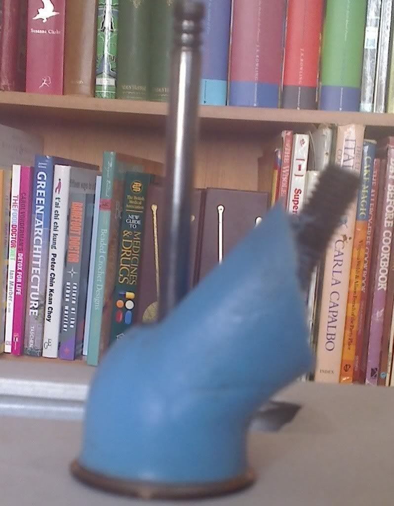
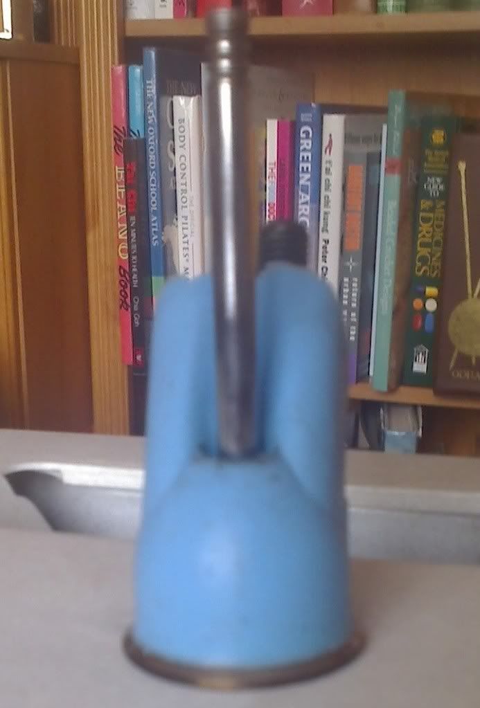
well on the 22nd i stuck some port moulding compound down the standard port iv used on the flow bench, didnt really have enough catalyst so its taken until now to harden (well, solidify), soooo here it is......
2.8 development thread http://www.e30zone.net/modules.php?name ... c&t=170822
m3.3.1 m20 thread - now running, chip needed - any volunteers?
http://www.e30zone.net/modules.php?name ... =viewtopic&
m3.3.1 m20 thread - now running, chip needed - any volunteers?
http://www.e30zone.net/modules.php?name ... =viewtopic&
-
HairyScreech
- Engaged to the E30 Zone
- Posts: 6265
- Joined: Sun Jan 21, 2007 11:00 pm
would seem the join from the roof of the runner into the bowl forms a very poor transition, theres quite a pronounced lip either side of the valve guide, which would explain why there has been such gain from working the roof back into the bowl.
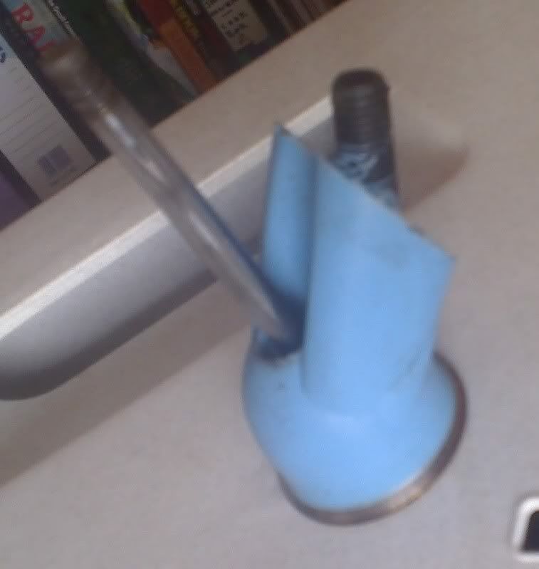
as we already knew the end of the valve guide and the tapered area before it costs a lot of port area and causes quite a bit of obstruction, simply bullet nosing the bronze guide and knife edging the tapered section would seen gains.
the short side radius dosent seem too bad, which i guess is why the head performs well in standard trim, the only thing i can see that would improve it is a multi angle cut on the seat or a multi angle seat combined with a 1mm oversize valve, as this would allow the seat to be cut a bit further out and a 70 ish degree cut to be made into the bowl to turn the air earlier and get the air wanting to turn and flow out the gap between the valve and the seat.
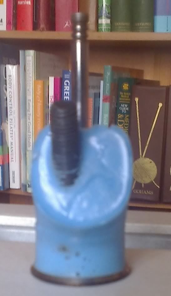
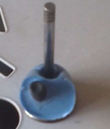
it would appear that the port is produced by having a casting core that produces the port runner, a cutter that goes down the valve guide to produce the bowl, and a further cut that produces the short side transition, (judging by the differing textures and cut patterns), this produces quite a few small transitions and differing textures, i would expect to see some kind of benefit from putting a sanding roll down the port and just smoothing the transitions and surfaces out.
simple thing to do, just get a bit of 5mm+ rod, cut a slot in it and then slip a piece of emery cloth down the slot, use this in a drill and reap the smooth as a babys bum benefit.
as we already knew the end of the valve guide and the tapered area before it costs a lot of port area and causes quite a bit of obstruction, simply bullet nosing the bronze guide and knife edging the tapered section would seen gains.
the short side radius dosent seem too bad, which i guess is why the head performs well in standard trim, the only thing i can see that would improve it is a multi angle cut on the seat or a multi angle seat combined with a 1mm oversize valve, as this would allow the seat to be cut a bit further out and a 70 ish degree cut to be made into the bowl to turn the air earlier and get the air wanting to turn and flow out the gap between the valve and the seat.
it would appear that the port is produced by having a casting core that produces the port runner, a cutter that goes down the valve guide to produce the bowl, and a further cut that produces the short side transition, (judging by the differing textures and cut patterns), this produces quite a few small transitions and differing textures, i would expect to see some kind of benefit from putting a sanding roll down the port and just smoothing the transitions and surfaces out.
simple thing to do, just get a bit of 5mm+ rod, cut a slot in it and then slip a piece of emery cloth down the slot, use this in a drill and reap the smooth as a babys bum benefit.
2.8 development thread http://www.e30zone.net/modules.php?name ... c&t=170822
m3.3.1 m20 thread - now running, chip needed - any volunteers?
http://www.e30zone.net/modules.php?name ... =viewtopic&
m3.3.1 m20 thread - now running, chip needed - any volunteers?
http://www.e30zone.net/modules.php?name ... =viewtopic&
-
HairyScreech
- Engaged to the E30 Zone
- Posts: 6265
- Joined: Sun Jan 21, 2007 11:00 pm
heres an illustration best i can on paint of what i mean by a +1 valve and multi angle seat,

as you can see the idea is to get the air to turn earlier and settle down so it can make it past the valve head at a tangent to the normal flow out the seat/port.
with a fluted bottom the bowl is encouraging the air out to the edge and past the valve, you have to imagine the air wants to flow and 45 degrees to the valve guide, as it has to negotiate the gap between the seat and the head.
2.8 development thread http://www.e30zone.net/modules.php?name ... c&t=170822
m3.3.1 m20 thread - now running, chip needed - any volunteers?
http://www.e30zone.net/modules.php?name ... =viewtopic&
m3.3.1 m20 thread - now running, chip needed - any volunteers?
http://www.e30zone.net/modules.php?name ... =viewtopic&
-
e30topless
- E30 Zone Team Member

- Posts: 13598
- Joined: Wed Aug 23, 2006 11:00 pm
- Location: surrounded by scrap
because Hennie is in SA I bet his head and pistons are from a 325is EvoSimon13 wrote:On my alpina touring engine which is post 91/2 built i think, the pistons had 2.7 and 9.7 written in the crown. Hennies heads look exactly the same as my engines!
they used the same donk as your C2
-
hennie
- E30 Zone Newbie

- Posts: 29
- Joined: Sat Nov 24, 2007 11:00 pm
the 2.7 is a eta crank knife edged balanced lightened flywheel 325 rods specially modified 84.5 325 pistons with a alpina copy head based on the one i have its running alpina ecu piggyback and maf
with the old alpina head it made 170kw
the cr has been bumped up new bigger injectors fitted exhaust system changed to a different design
i cant reveal more specs on this motor as it will land me in hot water as its not my design
my motor is a 328 crank 320 rods 325 stock 84.5mm pistons block is decked .3mm
the head im flowing is completed need to get it a cleanup skim and fit the new valves the intake valves will be swirled will post some picks soon
there is other things that has priority over finishing the head so its put on hold for a while
-
Simon13
- The longest resto in the world !
- Posts: 22697
- Joined: Mon Jan 10, 2005 11:00 pm
- Location: Camberley, Surrey don't u know
In answer to your FAO, i have the following, the stock 2.5 piston is 7.40mm the alpina slug was 5.70mm. Which isn't a huge difference
-
hennie
- E30 Zone Newbie
- Posts: 29
- Joined: Sat Nov 24, 2007 11:00 pm
updates 
will be starting to finish my head end of this month i have relocated and still need to unpack my garage goods
will be starting to finish my head end of this month i have relocated and still need to unpack my garage goods
-
tomislav
- E30 Zone Squatter
- Posts: 1633
- Joined: Thu Nov 29, 2007 11:00 pm
- Location: Faversham, Kent
Gonna watch this now i've just read it all!!!
Would be interesting to see some results
Would be interesting to see some results
'Assumption is the mother of all f**k ups'
-
eta
- E30 Zone Regular

- Posts: 356
- Joined: Fri Oct 26, 2007 11:00 pm
- Location: Glemsford Suffolk
Whats goin on Hairy Screech?
-
tomislav
- E30 Zone Squatter
- Posts: 1633
- Joined: Thu Nov 29, 2007 11:00 pm
- Location: Faversham, Kent
Anything happening with this thread?
Would be good to see new developments if anyone has any
Would be good to see new developments if anyone has any
'Assumption is the mother of all f**k ups'
-
HairyScreech
- Engaged to the E30 Zone
- Posts: 6265
- Joined: Sun Jan 21, 2007 11:00 pm
im sorry guys, things are happening, but at a snails pace due to a hell of a summer.
thanks to si13's generous donation of bits i have the heads to do the multi angle seats on, and a head with some slightly odd ports, but ill elaborate on that one later.
ill be back up at uni in a few weeks so will be back onto the job in earnest and hopefully normal service can resume.
thanks to si13's generous donation of bits i have the heads to do the multi angle seats on, and a head with some slightly odd ports, but ill elaborate on that one later.
ill be back up at uni in a few weeks so will be back onto the job in earnest and hopefully normal service can resume.
2.8 development thread http://www.e30zone.net/modules.php?name ... c&t=170822
m3.3.1 m20 thread - now running, chip needed - any volunteers?
http://www.e30zone.net/modules.php?name ... =viewtopic&
m3.3.1 m20 thread - now running, chip needed - any volunteers?
http://www.e30zone.net/modules.php?name ... =viewtopic&
-
reggid
- E30 Zone Squatter
- Posts: 1982
- Joined: Mon Jul 11, 2005 11:00 pm
- Location: Oz
for minimal head work i think you can do 90hp/L pretty comfortably on a 2.8L. The focus should be on matching the following.
CAM:
COMPRESSION:
EXHAUST: the exhaust primary length/bore and secondary length/bore.
INLET MANIFOLD: runner Bore/length and plenum configuration.
I have been using engine analyser pro software which correlated extremely well with my current build using actual head flow data, exhuast runner sizes, i cutup an intake manifold to measure etc etc. I played around with how to get some better topend and bottom end by proper choice of components. I have a pretty good idea of what things to change now and the correlation gives confidence that it is not garbage software.
I have some spare cylinder heads (731 and 885) which i am going to cast the ports with rubber so i can take some measurements and allow better visualisation and then cut up a cracked one to see how the shape can be optimised.
I am contemplating trying to reach 300 from my 3.1L when i pull her out and tinker again but i will only attempt this if i can get the numbers from the head as it is a full rebuild again which is costly.
E30 325is with M20B31
-
basketweave
- E30 Zone Newbie
- Posts: 45
- Joined: Mon Jun 13, 2011 11:00 pm
- Location: Sydney Australia
300hp from 3.1 litres in theory should not be a problem, depending on where you want the power to be. If it is for a race car, then lots of comp, cam and timing should see 300 at the flywheel but up over 7000rpms. IMO I have not seen a m20 fully developed yet, I have seen good engines with clever mods but nothing that emcompasses everthing that makes a high performance engine work well. I think a m20 would work well with a 86mm bore, 81-82 stroke (undersize offset big end bearings using eta crank), a nice long rod like 140mm or so, a light piston using factory dish dome for the 885 head or a flat top piston for the 731 head. Run a big cam, comp up around 12 to 1, ITB's of the right size, a handmade exhaust and aftermarket efi like autronic. Blueprinting the engine would be good too, like getting each combustion chamber excatly the same cc, and intake ports too, also torque plate honing the bores, deburring the crankcase etc all the usual race engine stuff.
-
reggid
- E30 Zone Squatter
- Posts: 1982
- Joined: Mon Jul 11, 2005 11:00 pm
- Location: Oz
basketweave wrote:300hp from 3.1 litres in theory should not be a problem, depending on where you want the power to be. If it is for a race car, then lots of comp, cam and timing should see 300 at the flywheel but up over 7000rpms. IMO I have not seen a m20 fully developed yet, I have seen good engines with clever mods but nothing that emcompasses everthing that makes a high performance engine work well. I think a m20 would work well with a 86mm bore, 81-82 stroke (undersize offset big end bearings using eta crank), a nice long rod like 140mm or so, a light piston using factory dish dome for the 885 head or a flat top piston for the 731 head. Run a big cam, comp up around 12 to 1, ITB's of the right size, a handmade exhaust and aftermarket efi like autronic. Blueprinting the engine would be good too, like getting each combustion chamber excatly the same cc, and intake ports too, also torque plate honing the bores, deburring the crankcase etc all the usual race engine stuff.
A 3.1L peaking at about 6.7 to 7k and running to 7.5k with everything sized accordingly is about the revs you need and much similar to a S50B30/32 interms of TQ and HP but not the same broad power band. I don't think you can have a 3L M20 with much higher peak without making big compromises in terms of useable power.
some interesting stuff shown in the simulations is that a longer rod 150mm lost power everywhere compared to a 135mm rod (only a few hp but there is an effect that the software picks up, for durability a longer rod won't hurt if you turn it much higher than stock) same with a bigger cam (i.e. duration) much better to increase area under lift curve with more aggressive profile and more lift that way you don't lose anything (apart from valve train durability). Some more intersting stuff is that the smaller stroke didn't make much less peak power but needed a higher RPM to make the power and less torque which is logical.
E30 325is with M20B31
-
basketweave
- E30 Zone Newbie
- Posts: 45
- Joined: Mon Jun 13, 2011 11:00 pm
- Location: Sydney Australia
Yes I agree about the power band, a high horsepower M20 would not be much fun in a street car. The S50 has the advantage of VANOS to adjust the LSA of the cams depending on the revs.
Its interesting a 150mm rod (not physically possible) lost power compared to a 135mm rod. How about a 140mm rod? Do the simulations account for a lighter piston that comes hand in hand with a longer rod?
A smaller stroke engine does make good power up high, it is common in many performance engines. Longer stroke engines feel really torquey just off idle but kinda run out of steam up high. Generally. S50 engines are an exception.
-
reggid
- E30 Zone Squatter
- Posts: 1982
- Joined: Mon Jul 11, 2005 11:00 pm
- Location: Oz
Vanos on an M20 would be handy!basketweave wrote:Yes I agree about the power band, a high horsepower M20 would not be much fun in a street car. The S50 has the advantage of VANOS to adjust the LSA of the cams depending on the revs.
Its interesting a 150mm rod (not physically possible) lost power compared to a 135mm rod. How about a 140mm rod? Do the simulations account for a lighter piston that comes hand in hand with a longer rod?
A smaller stroke engine does make good power up high, it is common in many performance engines. Longer stroke engines feel really torquey just off idle but kinda run out of steam up high. Generally. S50 engines are an exception.
i think the rod effect will be neglibible, if you plot out piston position as a function of crank angle and overlay the two cases it becomes quite obvious that is not much difference. No the software doesn't account for the mass of parts (lighter piston but heavier rod) other than putting in a typical inertial values.
the longer stroke helps to negate the effects of big cams, and big piping and also the lower operating rpms are an advantage but the demands on the head are higher for the same power level
E30 325is with M20B31
-
HairyScreech
- Engaged to the E30 Zone
- Posts: 6265
- Joined: Sun Jan 21, 2007 11:00 pm
i would expect the loss of power at 150mm rod is just a statistical anomaly, perhaps a quirk of the equations that means 150mm is the ideal length to give a quirk in that situation.
which version of AE are you using? iv got a version here but i dont think its much cop, it is quite old though.
the "running out of steam" at high engine speeds for longer stroke motors is due to the piston speed, as the velocity of the piston is proportional to the port velocity the faster the piston has to move the quicker you reach choke speed in the port.
it can be counter acted by larger ports, but thats just moving the power further up the rev range.
from other calculation the mass of the piston seems to be pretty negligible in terms of the overall power output, it has a much more significant effect on the physics inside the engine, but the over all output changes by very small amounts.
obviously provided the pistons dont weight 5kg+ or something silly like that.
i do think the manifold needs work, the flow bench shows trouble around 250hp, i know its been broken on the standard manifold, but it is still a known choke point.
i think i have found a good solution to that, but uni is in the way of silly designing/modifications right now.
as for exhaust i have a plan, which will probably involve using wave to simulate the flow and build some stepped primary short tube runners with anti reversion chambers and merged collectors to help extend the power band as far as possible.
would also like to thank si here as i have a euro spec Alpina c2 cam here to measure, along with some more cracked heads (which are really far gone) to get the multi angle seats done on.
for which i think i will knock the old seats out and just make some test profiles up from either aluminium or plastic tubing, allowing me to try out some radical profiles.
2.8 development thread http://www.e30zone.net/modules.php?name ... c&t=170822
m3.3.1 m20 thread - now running, chip needed - any volunteers?
http://www.e30zone.net/modules.php?name ... =viewtopic&
m3.3.1 m20 thread - now running, chip needed - any volunteers?
http://www.e30zone.net/modules.php?name ... =viewtopic&
-
Gunni
- E30 Zone Addict
- Posts: 2115
- Joined: Tue Jan 11, 2005 11:00 pm
- Location: Oxford
Simulations are just that, simulations.
Unless you have succesfully verified the complete results of a stock M20 compared to a simulated M20 stock and then modify can you make any assumptions about the modifications.
I say assumptions as that is all you can take away from a simulation.
Unless you have succesfully verified the complete results of a stock M20 compared to a simulated M20 stock and then modify can you make any assumptions about the modifications.
I say assumptions as that is all you can take away from a simulation.
-
HairyScreech
- Engaged to the E30 Zone
- Posts: 6265
- Joined: Sun Jan 21, 2007 11:00 pm
^^ thats my thoughts as well gunni, part of my original uni project was simply validation of results from flow benches vs cfd simulation.
the version of EAP i have been using would give perfect repeatable results for dead stock 2.5 using the flow of a stock head and the profile of a stock cam, but when known modifications were added the variation between the real results and the simulation were to big for me to bother going much further with it.
i would like a copy of dynomation to play with, but thats a bit too much money right now.
although i will add there that the version of EAP i had was an older version and a newer version my give much better correlation.
2.8 development thread http://www.e30zone.net/modules.php?name ... c&t=170822
m3.3.1 m20 thread - now running, chip needed - any volunteers?
http://www.e30zone.net/modules.php?name ... =viewtopic&
m3.3.1 m20 thread - now running, chip needed - any volunteers?
http://www.e30zone.net/modules.php?name ... =viewtopic&
-
reggid
- E30 Zone Squatter
- Posts: 1982
- Joined: Mon Jul 11, 2005 11:00 pm
- Location: Oz
I would call it a function of the mathematical model they use, perhaps the shorter rod helps mask that the 885 ports are way too big. Ant has said in the past that there is next to no difference in hp and tq between the 130 and 135mm rod on a 2.7L based on engines he has built. There is not enough difference between the two (and there can not be) to worry too much IMO. If getting new pistons it makes sense for a longer the rod since the less side load the better from a durability point of view. If you can get away with standard pistons but need to use 130mm rod in order to do so I wouldn’t worry at all.HairyScreech wrote:i would expect the loss of power at 150mm rod is just a statistical anomaly, perhaps a quirk of the equations that means 150mm is the ideal length to give a quirk in that situation.
which version of AE are you using? iv got a version here but i dont think its much cop, it is quite old though.
the "running out of steam" at high engine speeds for longer stroke motors is due to the piston speed, as the velocity of the piston is proportional to the port velocity the faster the piston has to move the quicker you reach choke speed in the port.
it can be counter acted by larger ports, but thats just moving the power further up the rev range.
from other calculation the mass of the piston seems to be pretty negligible in terms of the overall power output, it has a much more significant effect on the physics inside the engine, but the over all output changes by very small amounts.
obviously provided the pistons dont weight 5kg+ or something silly like that.
i do think the manifold needs work, the flow bench shows trouble around 250hp, i know its been broken on the standard manifold, but it is still a known choke point.
i think i have found a good solution to that, but uni is in the way of silly designing/modifications right now.
as for exhaust i have a plan, which will probably involve using wave to simulate the flow and build some stepped primary short tube runners with anti reversion chambers and merged collectors to help extend the power band as far as possible.
would also like to thank si here as i have a euro spec Alpina c2 cam here to measure, along with some more cracked heads (which are really far gone) to get the multi angle seats done on.
for which i think i will knock the old seats out and just make some test profiles up from either aluminium or plastic tubing, allowing me to try out some radical profiles.
I use a pretty recent version of EAP and correlation seems reasonable”¦”¦... I also use Pipemax and this gives the best info about head flow (CFM required to make a certain power, CFM required as a function of crank angle, port CSA to avoid choke and reversion and sizes which are best for torque and hp), intake runner lengths and CSA, and exhaust primary size and length, collector size and length, distance from tailpipe to primary. It is all based on empirical engine dyno data as well and very highly regarded by pro engine builders (mostly pushrod guys).
I don’t think the power drop off is due to the small port volume causing choke which is way too large as it is on an 885. The higher piston speed puts more demand on the head and simply the cam is not correctly matched to this so the head the head can’t ”asupply ”athe flow needed. Also equally important is the inability to evacuate the cylinder of exhaust gases leaves residual gas that prevents fresh charge entering and this quickly compounds as rpm rise. I think this is why Alpina ported the exhaust side more than the inlet side and fitted headers but maintained a relatively small camshaft.
IMO the best port for a 2.7L or less is the 200 head with lots of port work, the shape is superior and has small starting cross sectional area (CSA) which while in standard form is too small can be enlarged quite a bit for a performance application. There appears to be room (wall thickness) to get the port CSA correct without losing the steeper port angle and get a more efficient shape than the other two variants but most aren’t willing to pay for this. I’d probably more realistically be using a 731 to keep cost down as it somewhere between the 200 and 885 in terms of port size. The smaller port size of the 731 still gives more flexibility in what shapes can be created by material removal (as opposed to adding material) so you don’t get the huge ports. Many porters seem apprehensive to add material which is really what the 885 needs.
The real area of focus needed to unleash the M20 is the intake manifold IMO and there are few options currently available and those that are seem to be fatally flawed.
E30 325is with M20B31
-
HairyScreech
- Engaged to the E30 Zone
- Posts: 6265
- Joined: Sun Jan 21, 2007 11:00 pm
yes, as you say its not the "port" choking its the combination of valve seat, valve and throat that is choking.
iv got the calculations i did last year somewhere that gives the piston speed that produces choke in the valve.
basically the valve curtain area to cylinder volume ratio is not in a large engines favor, its the classic problem that 2v engines face.
try scaling you flow up by valve area and you will find the problem reduces.
the inlet valve is already too small on the 2.5 when compared to the inlet, needs to be around 1:0.7. and for the 2.5 its 1:0.85, thus a 43 or 44mm valve is more correct, infact it brings things back inline when compared to the bore area as well.
the faster the piston and the larger the bore relative to the throat area behind the valve (80% of the valve head - stem diameter) the worse the situation and the earlier the power drop off.
as you say the 885 needs work on its short side, but thats always the area of trouble on any head, just look at the levels the NASCAR engine builders go to get the ports up high.
i need to have a muck about with the CSA of the 885 port, im currently researching some new forms of resin that WILL hold to the bottom of the port in the long term and wont suffer from the heat.
having had a play with the 731 head i would forget it, it dosent flow as well by a long shot, even with a 42mm valve and port work to match.
the 731 head has a totally different roof, thus porting to the flow levels of a worked 885 will either be VERY hard or result in breaking through on the roof of the port.
there just isnt as much material to play with on the 731.
as for the 200 head i cant say much as there kind of non-existent here and those that are about are worn out scrap.
exhaust flow should be 60-80% of the inlet flow, that is why alpina enlarged the exhaust ports, but due to the change of the combustion chamber shape we can pretty much forget alpina as a base line, the hemi changes the flow totally and thus the exhaust flow will be totally different for a closed pent chamber.
in fact i had better high lift flow on the exhaust port of the standard head than the hemi chambered head, thus bringing me to the conclusion some of that was to make up for the hemi chamber.
intake manifold i am working on, i think there may even be a way to trigger a TVIS style system using the vanos output of a single vanos management.
pretty much the stock inlet is too long and too curved (which slows flow) to deliver the goods, its great for a 2.5, not so good for a 2.8 and not even close for 3l+.
something along the lines of the m50 manifold may be more suitable.
infact have you considered using silicon hose to join a cut m50 manifold to a cut 325 flange, similar to the method the bike throttle body conversions use.
2.8 development thread http://www.e30zone.net/modules.php?name ... c&t=170822
m3.3.1 m20 thread - now running, chip needed - any volunteers?
http://www.e30zone.net/modules.php?name ... =viewtopic&
m3.3.1 m20 thread - now running, chip needed - any volunteers?
http://www.e30zone.net/modules.php?name ... =viewtopic&
-
reggid
- E30 Zone Squatter
- Posts: 1982
- Joined: Mon Jul 11, 2005 11:00 pm
- Location: Oz
HairyScreech wrote:yes, as you say its not the "port" choking its the combination of valve seat, valve and throat that is choking.
iv got the calculations i did last year somewhere that gives the piston speed that produces choke in the valve.
basically the valve curtain area to cylinder volume ratio is not in a large engines favor, its the classic problem that 2v engines face.
try scaling you flow up by valve area and you will find the problem reduces.
the inlet valve is already too small on the 2.5 when compared to the inlet, needs to be around 1:0.7. and for the 2.5 its 1:0.85, thus a 43 or 44mm valve is more correct, infact it brings things back inline when compared to the bore area as well.
the faster the piston and the larger the bore relative to the throat area behind the valve (80% of the valve head - stem diameter) the worse the situation and the earlier the power drop off.
as you say the 885 needs work on its short side, but thats always the area of trouble on any head, just look at the levels the NASCAR engine builders go to get the ports up high.
i need to have a muck about with the CSA of the 885 port, im currently researching some new forms of resin that WILL hold to the bottom of the port in the long term and wont suffer from the heat.
having had a play with the 731 head i would forget it, it dosent flow as well by a long shot, even with a 42mm valve and port work to match.
the 731 head has a totally different roof, thus porting to the flow levels of a worked 885 will either be VERY hard or result in breaking through on the roof of the port.
there just isnt as much material to play with on the 731.
as for the 200 head i cant say much as there kind of non-existent here and those that are about are worn out scrap.
exhaust flow should be 60-80% of the inlet flow, that is why alpina enlarged the exhaust ports, but due to the change of the combustion chamber shape we can pretty much forget alpina as a base line, the hemi changes the flow totally and thus the exhaust flow will be totally different for a closed pent chamber.
in fact i had better high lift flow on the exhaust port of the standard head than the hemi chambered head, thus bringing me to the conclusion some of that was to make up for the hemi chamber.
intake manifold i am working on, i think there may even be a way to trigger a TVIS style system using the vanos output of a single vanos management.
pretty much the stock inlet is too long and too curved (which slows flow) to deliver the goods, its great for a 2.5, not so good for a 2.8 and not even close for 3l+.
something along the lines of the m50 manifold may be more suitable.
infact have you considered using silicon hose to join a cut m50 manifold to a cut 325 flange, similar to the method the bike throttle body conversions use.
You say the intake valve is too small for the intake port, what is to say the port isn’t too larger for the valve which is my opinion based on what I simulated in pipemax which is well proven. I am talking about average CSA.
There is a local knowledgeable guy that has a 240 hp@wheels race engine with displacement of 2.7L using a 731 head with 42mm intake valve and 35mm exhaust valve. This is proof enough that there is potential in the 731 head. There is also another guy I know who got the 731 with 42/36 valves to flow the same as the stock 885 without out having to hog out the ports. The same flow with smaller port CSA the better in our case. For a standard head the 885 is the king but for a well developed I would be starting with a 731 and using 43 or 44mm valves on the inlet and 36 or 37mm exhaust valve corresponding otherwise on any decent cam they smack into each other.
If I was to develop a mild M20 using the 885 I would look at adding us much material as I could without hurting flow before porting anything.
This
http://www.e30tech.com/forum/attachment ... 1319356345
seems like enough material to me but there isn’t the need to open it up much anyway otherwise you end up with ports the size of a 885 which so far has not produced anything close to being remarkable.
Don’t take this the wrong way but I am not sure how much experience you have porting heads or building engines but just because you can’t does mean it can’t be done. There are some reputable builders around the world who use the 731 as their starting point not to mention the other local guys who use the 731. It does require much more work but there are enough suggestions that it will end up superior that it is worth further investigation. On a 2.7L if using the 731 you don’t need to match the 885 for flow as most aren’t targeting higher than what the current limits of the 885 are anyway.
I have cast all the standard inlet and exhaust ports for the 200,731,885 and may be able to borrow the Alpina head I gave away to cast the exhaust side to see if there is anything significant in what Alpina did. Maybe it will just be the chamber work that produced the gains but the port was physically larger last time I measured.
The Pushrod guys do a lot of work on their heads and even cast new ones (many race engines are better castings) but nobody really does this (that I know about) for the humble M20 of course there isn’t enough demand and the M10 and M30 are better propositions anyway.
I was thinking of an S38 style plenum with benefits of single and dual plane manifold.
E30 325is with M20B31
-
HairyScreech
- Engaged to the E30 Zone
- Posts: 6265
- Joined: Sun Jan 21, 2007 11:00 pm
dual plane seems to be a trick for even flow to each cylinder, which is why they are more used in motorsport where engines are running a restrictor.
restrictors are a pain in the ass in performance applications, our formula student team redesigned there manifold to optimize it for a mandated 22mm restrictor, the result was a 3 foot long taper on the plenum, still 95hp through a 22mm hole is good whack.
i think you just hit my 731 problem. i couldnt get any good flow when others could, and iv been forgetting one important factor of the head i used, its combustion chambers were RESHAPED THE SAME AS An 885 HEAD for the dish piston.
i just hadnt questioned this as i was focused on using the compact chamber of the 885 piston but theres no reason that cant be solved.
when i go home to sort the mot this week ill look at the m52b28 piston again, as the 885 MUST be used with b25 pistons for best chamber shape, but theres nothing to stop a 731 being used with flat topped m52b28 pistons as it was designed for in the first place.
from there its some simple shape tweeks to even out the chamber around the plug and reduce the ott compression and there could be a winner in it.
it will still keep the intended compact closed chamber pent roof design that the bmw requires.
infact a slight bowl may still have to be put on the piston anyway, but that will still result in a compact chamber with correct squish band.
i was forgetting the other reason for discounting the 731 which was the combustion chamber shape match up, which is no good for a b25 piston. BUT and its a big BUT the m52b28 pistons could negate this, and save me the trouble of making the b25 pistons work.
i have 2 "new" cracked heads to play with, so i will use them for the multi angle seats, and to finish developing the 885, part of which was to reduce the port volume or "plastic work" as it gets known.
i will fully develop the 885 head still, mostly as i have 2 and also because the market is biggest and a 731 would need chamber tweeks for the b25.
i have a 731 but its a bit knackered, i can replace the material hogged out with some clay just for testing purposes, as it hasnt got to run.
ill retest in some time this week and let you know what happens.
should also have the CFD working within a couple of months, so i can produce the "scientifically correct" port designs, this may well shift the game in terms of port shapes as nothing helps design a port like being able to see the "exact" velocity and flow and any given point.
2.8 development thread http://www.e30zone.net/modules.php?name ... c&t=170822
m3.3.1 m20 thread - now running, chip needed - any volunteers?
http://www.e30zone.net/modules.php?name ... =viewtopic&
m3.3.1 m20 thread - now running, chip needed - any volunteers?
http://www.e30zone.net/modules.php?name ... =viewtopic&
-
HairyScreech
- Engaged to the E30 Zone
- Posts: 6265
- Joined: Sun Jan 21, 2007 11:00 pm
im going to figure out the chamber volumes and compression ratios to see how much of a dish would have to be put into a m52b28 piston as i think the compression will be very high, i think 12:1 has been mentioned before.
i forget, what pistons have your got in yours and whats your comp ratio at the moment?
ill run the numbers to see what change you would get from the smaller chamber.
oh and its not that the valve is too small for the port, infact as you say the port is actually over the recommended ratio.
its that the valve area is to small for the bore area, the larger the valves are in relation to the bore the better.
for example if you only had 10mm^2 valve area and 1000mm^2 bore area, the speed that the air is going past the valve needs to be 100 times the piston speed if no depression is to develop in the bore.
this can be held true as the flow is considered incompressable which is not far from the truth at sub sonic speeds, infact the reason for the 25" of water is its the average depression over the intake cycle, that 25" of water translates to a mere 0.9032psi.
2.8 development thread http://www.e30zone.net/modules.php?name ... c&t=170822
m3.3.1 m20 thread - now running, chip needed - any volunteers?
http://www.e30zone.net/modules.php?name ... =viewtopic&
m3.3.1 m20 thread - now running, chip needed - any volunteers?
http://www.e30zone.net/modules.php?name ... =viewtopic&
-
gooner1
- Out humping Reindeer
- Posts: 13280
- Joined: Fri Apr 14, 2006 11:00 pm
- Location: Northampton.For my sins.
Talking of 200 heads, maybe this chap wasn't so full
of it as some thought.
http://www.e30zone.net/modules.php?name ... t=200+head
of it as some thought.
http://www.e30zone.net/modules.php?name ... t=200+head

-
HairyScreech
- Engaged to the E30 Zone
- Posts: 6265
- Joined: Sun Jan 21, 2007 11:00 pm
yes, tis the reason i simply said "im listening" as the tech he talks about is real, and i dont doubt that rgm have dont it, but i would like custard proof.
tbh the cylinder filling issue is not so bad for the bore of the 2l, the valve size on a 2l is ok, but as the bore increases the valve size wont keep up, its a logarithmic? (might be it) relation ship.
tbh the cylinder filling issue is not so bad for the bore of the 2l, the valve size on a 2l is ok, but as the bore increases the valve size wont keep up, its a logarithmic? (might be it) relation ship.
2.8 development thread http://www.e30zone.net/modules.php?name ... c&t=170822
m3.3.1 m20 thread - now running, chip needed - any volunteers?
http://www.e30zone.net/modules.php?name ... =viewtopic&
m3.3.1 m20 thread - now running, chip needed - any volunteers?
http://www.e30zone.net/modules.php?name ... =viewtopic&
-
reggid
- E30 Zone Squatter
- Posts: 1982
- Joined: Mon Jul 11, 2005 11:00 pm
- Location: Oz
Here are some cross sections
200

731

885

In terms of normalised average cross section (port volume)
200 as baseline
200 = 1.00
731 = 1.32
885 = 1.64
731 as baseline
200 = 0.76
731 = 1.00
885 = 1.24
885 as baseline
200 = 0.61
731 = 0.80
885 = 1.00
You only need 150-160cfm @ 28”a to make 240-250hp so even if it falls short of the 885 in ultimate steady state flow it doesn’t matter. So if you have the flow that you need with a smaller port from 200 or 731 then you are better off than having a port 30% larger but giving 20CFM more”¦.the velocity will do wonders. The piston and chamber need to match with the right CR. Once you have that its just playing with cam and manifolds.
I have CFD but getting the geometry that represents a real port is a difficult task. The mesh to account for different valve angles needs to be quite small to get enough resolution. I think the biggest advantage would be the exhaust side as you get simulate higher and realistic pressure differentials.
200
731
885
In terms of normalised average cross section (port volume)
200 as baseline
200 = 1.00
731 = 1.32
885 = 1.64
731 as baseline
200 = 0.76
731 = 1.00
885 = 1.24
885 as baseline
200 = 0.61
731 = 0.80
885 = 1.00
You only need 150-160cfm @ 28”a to make 240-250hp so even if it falls short of the 885 in ultimate steady state flow it doesn’t matter. So if you have the flow that you need with a smaller port from 200 or 731 then you are better off than having a port 30% larger but giving 20CFM more”¦.the velocity will do wonders. The piston and chamber need to match with the right CR. Once you have that its just playing with cam and manifolds.
I have CFD but getting the geometry that represents a real port is a difficult task. The mesh to account for different valve angles needs to be quite small to get enough resolution. I think the biggest advantage would be the exhaust side as you get simulate higher and realistic pressure differentials.
E30 325is with M20B31
-
HairyScreech
- Engaged to the E30 Zone
- Posts: 6265
- Joined: Sun Jan 21, 2007 11:00 pm
what cad/cfd are you using, as a lot of mine will be done on ansys, so provided you can open the files ill send them over when im done, the trick with the valves is to use a localised fine mesh around the tricky spots.
i know this is possible with ansys but not 100x on any of the other (although quite likely)
have you seen this:
http://www.e30tech.com/forum/showthread ... 38&page=33
http://e21jps.webs.com
i would say there is a good example of everything discussed here put into practice, although again as he says there is more possible.
the headers are particularly good.
2.8 development thread http://www.e30zone.net/modules.php?name ... c&t=170822
m3.3.1 m20 thread - now running, chip needed - any volunteers?
http://www.e30zone.net/modules.php?name ... =viewtopic&
m3.3.1 m20 thread - now running, chip needed - any volunteers?
http://www.e30zone.net/modules.php?name ... =viewtopic&
-
HairyScreech
- Engaged to the E30 Zone
- Posts: 6265
- Joined: Sun Jan 21, 2007 11:00 pm
heres the photos from the 42/36mm valve combo installed in the 731 head i had:
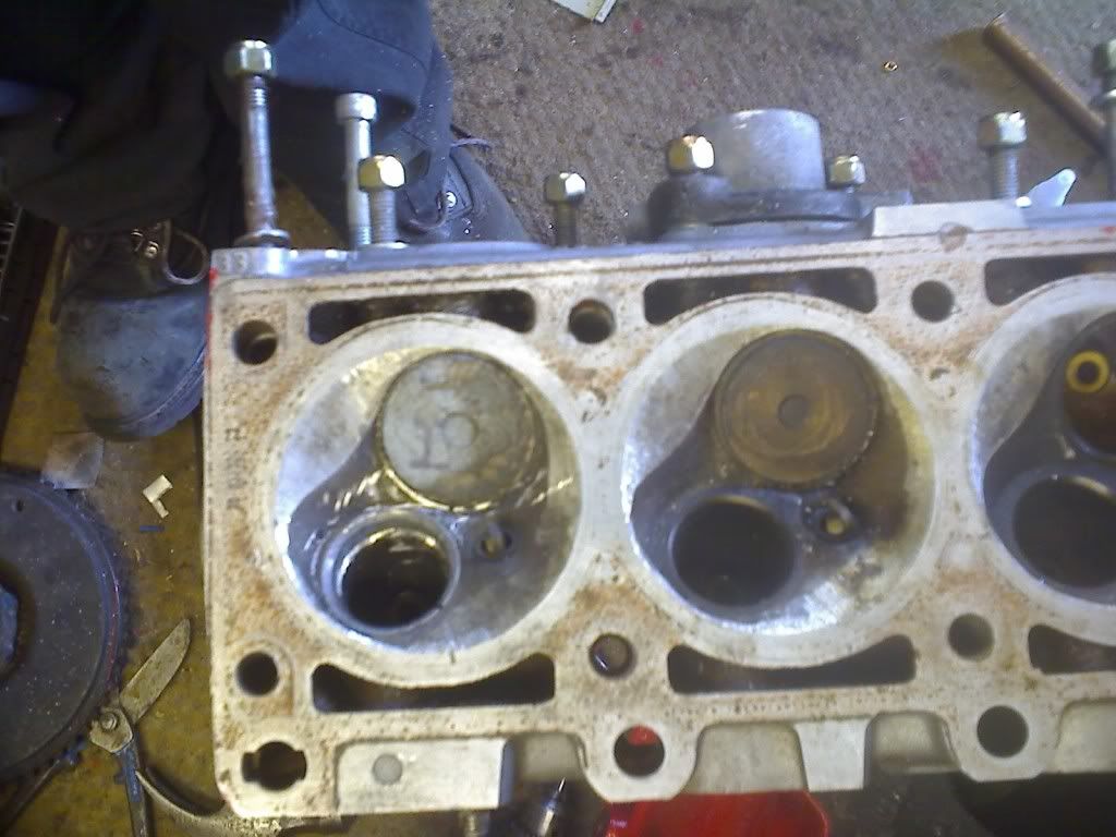
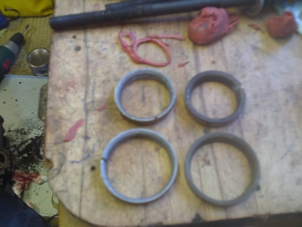
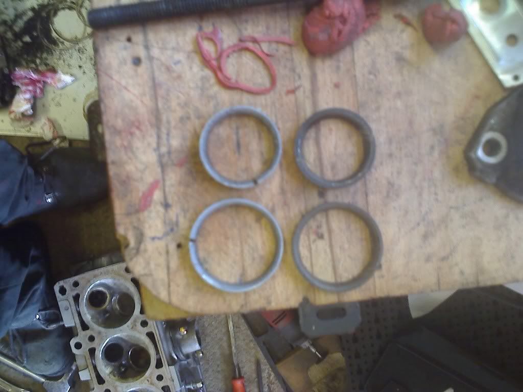
this head had been running as an emergency measure on a friends 325, now in order to make that one work the quench pads had been cut to the same shape as the 885 head.
now that where i think my problems were.
the 731 and 200 do have a theoretically better shape, with the 200 there being the best, although i do think the 731 (if it flows better unmodified) has the best.
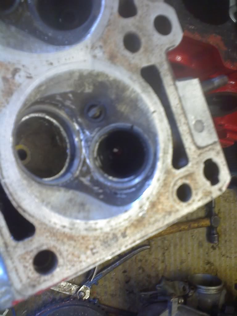
theres not a lot of material on the 731 port, so its all going to be down to shape, the sort side radius there is a little abrupt.
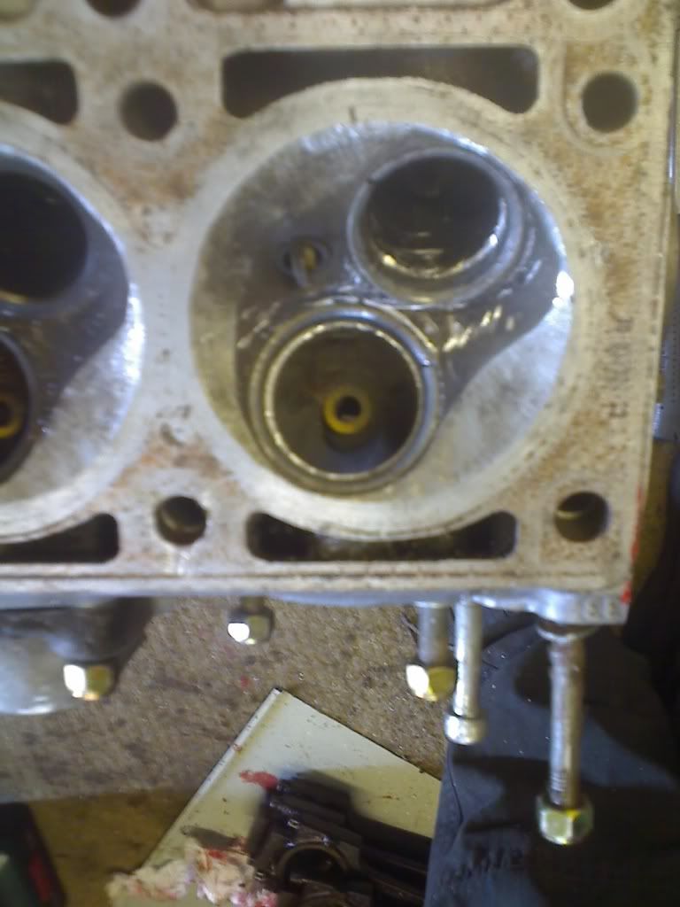
although as the throat needs enlarging for the 42mm valve (see above) there is a lot of scope for continuing the 70 degree throat cut quite a way, this should both move the short side radius back up the port allowing more time for the flow to equalize and also correct the turbulence inducing bowl at the back of the valve these things have.
for reference i got 152cfm at 10.5mm lift and 161cfm at 12.6mm lift from the 731 i had, which was 168 and 172cfm on the best 885 so far along with 164 and 169 cfm on a stock head.
bearing in mind neither of these had a multi angle seat, which could equate to as much as another 5% or 7-8cfm on the 731, putting it on par with the stock 885 and as you say a much increased velocity.
180 cfm is my real target, but i think this is only possible with a 43/44mm valve.
also bear in mind all of my tests have been at superflow standard 25" of water.
what CSA have you got for the 731, i have it on very good authority that the port is ideally 0.9*the valve seat diameter.
so for a 42mm valve your looking at 1246mm^2 or 39.8mm diameter.
with this in mind its been recommended that the port velocity be around 80m/s.
from what i gather this is the bench marks used when designing some VERY high performance engines such as the judd v8s and super 1600 rally engines.
(for reference - the reason for there significantly elevated HP at high rpm is there large valve to bore ratio meaning that they still have 0.9*seat diameter ports and 80m/s its just a lot higher up the rev range as both of these are proportional to the valve size and piston speed.
the short stroke and large bore with 4v/cyl produce these high rpms)
this head had been running as an emergency measure on a friends 325, now in order to make that one work the quench pads had been cut to the same shape as the 885 head.
now that where i think my problems were.
the 731 and 200 do have a theoretically better shape, with the 200 there being the best, although i do think the 731 (if it flows better unmodified) has the best.
theres not a lot of material on the 731 port, so its all going to be down to shape, the sort side radius there is a little abrupt.
although as the throat needs enlarging for the 42mm valve (see above) there is a lot of scope for continuing the 70 degree throat cut quite a way, this should both move the short side radius back up the port allowing more time for the flow to equalize and also correct the turbulence inducing bowl at the back of the valve these things have.
for reference i got 152cfm at 10.5mm lift and 161cfm at 12.6mm lift from the 731 i had, which was 168 and 172cfm on the best 885 so far along with 164 and 169 cfm on a stock head.
bearing in mind neither of these had a multi angle seat, which could equate to as much as another 5% or 7-8cfm on the 731, putting it on par with the stock 885 and as you say a much increased velocity.
180 cfm is my real target, but i think this is only possible with a 43/44mm valve.
also bear in mind all of my tests have been at superflow standard 25" of water.
what CSA have you got for the 731, i have it on very good authority that the port is ideally 0.9*the valve seat diameter.
so for a 42mm valve your looking at 1246mm^2 or 39.8mm diameter.
with this in mind its been recommended that the port velocity be around 80m/s.
from what i gather this is the bench marks used when designing some VERY high performance engines such as the judd v8s and super 1600 rally engines.
(for reference - the reason for there significantly elevated HP at high rpm is there large valve to bore ratio meaning that they still have 0.9*seat diameter ports and 80m/s its just a lot higher up the rev range as both of these are proportional to the valve size and piston speed.
the short stroke and large bore with 4v/cyl produce these high rpms)
2.8 development thread http://www.e30zone.net/modules.php?name ... c&t=170822
m3.3.1 m20 thread - now running, chip needed - any volunteers?
http://www.e30zone.net/modules.php?name ... =viewtopic&
m3.3.1 m20 thread - now running, chip needed - any volunteers?
http://www.e30zone.net/modules.php?name ... =viewtopic&
-
reggid
- E30 Zone Squatter
- Posts: 1982
- Joined: Mon Jul 11, 2005 11:00 pm
- Location: Oz
I was at his place on Sat, he cut up those heads”¦”¦”¦..HairyScreech wrote:what cad/cfd are you using, as a lot of mine will be done on ansys, so provided you can open the files ill send them over when im done, the trick with the valves is to use a localised fine mesh around the tricky spots.
i know this is possible with ansys but not 100x on any of the other (although quite likely)
have you seen this:
http://www.e30tech.com/forum/showthread ... 38&page=33
http://e21jps.webs.com
i would say there is a good example of everything discussed here put into practice, although again as he says there is more possible.
the headers are particularly good.
It is an example of engineering something based on theory and knowledge to end up with something that is well balanced.
I use solidworks which has an automatic mesher and you can specify finer mesh but haven’t worked out how to locally refine it, making the entire model finer is no problem but takes more time to solve an is inefficient”¦
The key with the 200 and 731 is like you say if you enlarge the seats the short side can be dramatically improved.
Some ports do need a little more CSA near the bowl and valve guide to slow the air down before they have to make the abrupt short side, but the entry and port proper should be sized to 260-280ft/s (~80-85m/s). A bigger valve and seat would help with this slowing the air near the turn which helps with pressure recovery. A steeper angle port could be smaller since there is no real short side but that does not apply to the M20.
40mm is far too large IMO, I think stock 731 is about 35mm round shape at the entry which is not far from what I think will work well for a 2.8L. The stock 885 is only about 1-2 mm larger envelope so that would be 36-37mm but is wider on the top to make it more of a D-shape (opposite of what’s needed i.e. should be wider along the bottom) and is why the area is works out about 25% larger.
The intake bore starts at 35mm and increases to via the taper to 45mm at the plenum bellmouth (from memory).
It seems that most know that bigger is not better but the problem is knowing when something is already too big.
E30 325is with M20B31
-
reggid
- E30 Zone Squatter
- Posts: 1982
- Joined: Mon Jul 11, 2005 11:00 pm
- Location: Oz
i noticed you said 0.9 times the valve seat diameter but used the valve diameter in the calculation is that delibrate? The seat ID is about 37mm which becomes 35mm when the 90% rule of thumb you stated is used.
160cfm@25" is probably 170@ 28" and according to pipemax thats all you need as long as the CSA around the guide is not too small which it is stock, something 32mm to 35mm. Remove the guide and clear away the casting boss maintaining the smooth shape and then bullet head the guide and reinstall.
160cfm@25" is probably 170@ 28" and according to pipemax thats all you need as long as the CSA around the guide is not too small which it is stock, something 32mm to 35mm. Remove the guide and clear away the casting boss maintaining the smooth shape and then bullet head the guide and reinstall.
E30 325is with M20B31
-
daimlerman
- **BANNED**
- Posts: 15968
- Joined: Mon Feb 27, 2006 11:00 pm
- Location: Grumpy Old Man
I have a 200 head sat in my parts stash,once you pair have decided just what it needs to make it work with my 2.7 and an ex E21 323 cam...... 
Youth is wasted on the young.
-
gooner1
- Out humping Reindeer
- Posts: 13280
- Joined: Fri Apr 14, 2006 11:00 pm
- Location: Northampton.For my sins.
Spent far too much on my 885 head to change it now, but interesting stuff all the same.
Particularity interested in thoughts on the E21 323 cam, as Malc mentions.
Particularity interested in thoughts on the E21 323 cam, as Malc mentions.