
the m20 developement thread. Some progress and a new lump.
Moderator: martauto
-
town325i
- E30 Zone Team Member

- Posts: 7050
- Joined: Thu Jun 26, 2008 11:00 pm
- Location: cannock staffordshire
Tbh i feel you are looking to in depth into this for a home build no one is going to be able to build an engine to the same standard as companies like alpina or hartge

-
hennie

- E30 Zone Newbie

- Posts: 29
- Joined: Sat Nov 24, 2007 11:00 pm
the alpina pistons had a shallower dish in the piston than the stock pistons
-
johnt0709
- E30 Zone Addict

- Posts: 2291
- Joined: Mon Nov 06, 2006 11:00 pm
- Location: West of Scotland
Can I see the executive summary when your finished?? 
Last edited by johnt0709 on Mon Jun 28, 2010 1:03 pm, edited 1 time in total.
-
bilun777
- E30 Zone Regular

- Posts: 271
- Joined: Mon Dec 31, 2007 11:00 pm
- Location: Nr Lincoln
I fitted my inlet manifold to my rebuilt head 2 days ago. I was abit pee'd off after neatly trimming my gaskets to fit the D shaped head inlets to find the manifold tubes where oval and didn't remotely match the head.I would suggest that matching the ports here[and on the exhaust side which I believe Alpina did] could show abetter result than messing with the chamber shapes? 
If it aint broke don't fix it!
-
m_jermyn
- E30 Zone Team Member
- Posts: 4208
- Joined: Sat Mar 14, 2009 11:00 pm
- Location: Sydney Australia Mate
What head and manifold where you using?
-
bilun777
- E30 Zone Regular
- Posts: 271
- Joined: Mon Dec 31, 2007 11:00 pm
- Location: Nr Lincoln
Standard m20b25/885 head and manifold[out of interest the engine ran beautifully ,despite cracks through 5 of the camshaft journals.... mind you it did deposit about 2 litres of oil into the coolant on the 240 mile journey home when I bought it]m_jermyn wrote:What head and manifold where you using?
If it aint broke don't fix it!
-
HairyScreech
- Engaged to the E30 Zone
- Posts: 6265
- Joined: Sun Jan 21, 2007 11:00 pm
actually often a man at home can spend more time and take more care and end up producing something far superior to a mass produced component.town325i wrote:Tbh i feel you are looking to in depth into this for a home build no one is going to be able to build an engine to the same standard as companies like alpina or hartge
there may be things that give a small gain here and there that were just to expensive and time consuming to do commercially in the 80/90s.
a lot of small things that may have been prohibitively expensive for alpina, lets face it who was going to pay an extra £2000 for engine work in 1986 on top of the alpina conversion price for perhaps 10% more?
if these tricks can be discovered then they can be replicated by others.
any one can replicate a component it takes in depth work like this to work out what is correct in the first place.
once we know whats required anyone can pick up a set of die grinder bits and replicate what i have done and make an improvement for the grand total of £50
but where to take the material out requires work like this.
if i fit the large valves and then compliment them with porting then you can have the valves and seats fitted for £300.
but is it worth it and where do you cut the port to help things compliment the valve? thats where work like this is needed.
replication is simple at home, even if you dont know why your doing it.
in order to design or create the original pattern then you need to know why your doing things and what effect your having.
example, i could give that head to my dad and tell him to grind the next port along to match the first, he wouldnt know why hes cutting material in each spot and what effect hes having, but he would produce a port almost the same as the first and we know that what hes done is improve things not lose flow.
actually it means completely the opposite, theres a lot of room for improvement, but its not simply from the port.reggid wrote:it means there is not much improvement to be had so it should not be a prioritydaimlerman wrote:In terms that I can understand,what does it all mean,please?
the results show that the port work gains about 5-7% (working off my head as its not infront of me) which for simple port work with no plastic work and no valve or seat work is not bad.
especially on a port that is not bad as standard.
the thing it shows is there is a massive potential gain by either opening up the valve size and matching the port to the bigger size as there are real potential improvements around the floor of the port.
the other thing that will yeild more gain is changing the valve seat geometry, as after the second round of flow bench work it has been noticed that the shape of the seat could do with much improvement.
if both of these are combined then an even bigger gain could be realised.
with that said back to my first point. someone has to do it and quantify what they have done before we know what to do.
2.8 development thread http://www.e30zone.net/modules.php?name ... c&t=170822
m3.3.1 m20 thread - now running, chip needed - any volunteers?
http://www.e30zone.net/modules.php?name ... =viewtopic&
m3.3.1 m20 thread - now running, chip needed - any volunteers?
http://www.e30zone.net/modules.php?name ... =viewtopic&
-
HairyScreech
- Engaged to the E30 Zone
- Posts: 6265
- Joined: Sun Jan 21, 2007 11:00 pm
right back to the results, iv been to busy with personal crap to fiddle with crusty old low comp boat anchors.
first up, an explanation of the raw results. (bearing in mind this is the way i have been taught to do it, which anyone that works to superflows industry standard technique will be able to do.)
in order to make comparisons we generally use a percentage of the valve diameter as the lift values.
the IS technique says go up in 5% steps to 40% if possible, which for us gives the mm lift shown up to 14.7mm which is the most you can go to as the retainer hits the stem seal and the spring is coil bound.
the test pressure differential is 25" of water, which is given as the mean of the depression in to port of a running engine and again sugested as the industry standard, im always weary of tests done at anything lower than this as its not a true test of whats going on and can mask a lot of turbulence etc.
2.8 development thread http://www.e30zone.net/modules.php?name ... c&t=170822
m3.3.1 m20 thread - now running, chip needed - any volunteers?
http://www.e30zone.net/modules.php?name ... =viewtopic&
m3.3.1 m20 thread - now running, chip needed - any volunteers?
http://www.e30zone.net/modules.php?name ... =viewtopic&
-
HairyScreech
- Engaged to the E30 Zone
- Posts: 6265
- Joined: Sun Jan 21, 2007 11:00 pm
the tests are done using a set of calibrated holes (flow ranges). you go up in the range gradually in order to get better accuracy at lower flows.
the readout is in a % of the flow range and each of the holes has its own max CFM so its a simple case of multiplying the max by the % shown.
the leakage test is a check done with the valves closed to make sure the chamber and head is sealed.
if your leaking then you need to remove it from the raw cfm as your getting a false result otherwise.
however it is piss easy to get no leaks so i try to make sure.
the test cfm is the result of all that ^.
now by doing the cfm/square inch we can use a theoretical maximum that can flow through a valve and work out the maximum potential for the valve.
this gives us an indication of how well things are working and how much room for improvement there is.
2.8 development thread http://www.e30zone.net/modules.php?name ... c&t=170822
m3.3.1 m20 thread - now running, chip needed - any volunteers?
http://www.e30zone.net/modules.php?name ... =viewtopic&
m3.3.1 m20 thread - now running, chip needed - any volunteers?
http://www.e30zone.net/modules.php?name ... =viewtopic&
-
HairyScreech
- Engaged to the E30 Zone
- Posts: 6265
- Joined: Sun Jan 21, 2007 11:00 pm
(now my apologies for splitting this into several posts but i want to keep this easy to read and follow, which a massive single post wont be, but using a couple then people can quote individual bits for clarification and can easily pick up where the left off when reading. let me know if you want me to switch it up mods.) 
with what all the values are explained onto the actual testing results,
first off the head isnt bad for a standard head, iv seen better but iv also see a hell of a lot worse. the flow per inch is in the 70+% range and peaks around 86%. which means theres only a theoretical 14% to be had there at that particular lift/diameter but a lot more at other areas.
it would appear that the flow is around 170 cfm, which theoretically should allow for 240hp.
which interestingly enough is about all iv found from searching from an engine with a standard head.
now 240hp is good but where would we be if only good was good enough.
theres a few other things to bear in mind before looking too much at the results
1. you only get the peak flow your cam can lift to. for the m20 the standard is around 10.5mm lift and the highest iv found was 12.5mm shrick 306 degree monster cam that would be far better off in an f1 car than a daily driver.
2. the valve dosent open to 10.5mm instantly and then return instantly, it opens with the cam profile, so all of the lift up to this point is critical for improvement as well.
in some ways the lower lifts could be considered more important as the valve is partially open for longer than it is at full lift.
3. a valve wont flow any more once it has been opened 25% of its diameter, as the curtain area equals the valve throat area. so that is why the curves drop off and why theres little point in lifting a valve too much.
4. the peak cfm the valve will flow gives your max possible power
5. the % potential is an indication of how efficiently the air is getting past not only the port but the valve and seat as well. in order to get the maximum all of these things need to work together at all lifts.
the standard ports flow well but there not perfect and dont flow enough to get to 100hp/l (about 190cfm for the 2. so onto the porting.
with what all the values are explained onto the actual testing results,
first off the head isnt bad for a standard head, iv seen better but iv also see a hell of a lot worse. the flow per inch is in the 70+% range and peaks around 86%. which means theres only a theoretical 14% to be had there at that particular lift/diameter but a lot more at other areas.
it would appear that the flow is around 170 cfm, which theoretically should allow for 240hp.
which interestingly enough is about all iv found from searching from an engine with a standard head.
now 240hp is good but where would we be if only good was good enough.
theres a few other things to bear in mind before looking too much at the results
1. you only get the peak flow your cam can lift to. for the m20 the standard is around 10.5mm lift and the highest iv found was 12.5mm shrick 306 degree monster cam that would be far better off in an f1 car than a daily driver.
2. the valve dosent open to 10.5mm instantly and then return instantly, it opens with the cam profile, so all of the lift up to this point is critical for improvement as well.
in some ways the lower lifts could be considered more important as the valve is partially open for longer than it is at full lift.
3. a valve wont flow any more once it has been opened 25% of its diameter, as the curtain area equals the valve throat area. so that is why the curves drop off and why theres little point in lifting a valve too much.
4. the peak cfm the valve will flow gives your max possible power
5. the % potential is an indication of how efficiently the air is getting past not only the port but the valve and seat as well. in order to get the maximum all of these things need to work together at all lifts.
the standard ports flow well but there not perfect and dont flow enough to get to 100hp/l (about 190cfm for the 2.
2.8 development thread http://www.e30zone.net/modules.php?name ... c&t=170822
m3.3.1 m20 thread - now running, chip needed - any volunteers?
http://www.e30zone.net/modules.php?name ... =viewtopic&
m3.3.1 m20 thread - now running, chip needed - any volunteers?
http://www.e30zone.net/modules.php?name ... =viewtopic&
-
HairyScreech
- Engaged to the E30 Zone
- Posts: 6265
- Joined: Sun Jan 21, 2007 11:00 pm
one other thing about the standard port it would appear to become turbulent at the end, noticeable by the drop in flow and the fact the port was howling at me by that point. an issue that others have found before.
i need to do further work on the exhausts so for now im going to ignore them for now.
the first lot of porting was done pretty blind. it wasnt a structured aproach and was just going by feel. to not make a loss on the inlet side was a win, even using si's alpina photos as a guide i was still doing it with out any real guide as i had only a few photos as a guide of what to do (in this instance not really enough).
the hemi head didnt behave as i expected.
it produced a good bit more flow at the lower lifts, which was enough to be a noticeable gain
the curve ball was it just stopped flowing at higher lifts.
as yet im not sure 100% why this was, the current theory is flow separation caused by the angle the air has to exit the valve once the head is taken out.
once the 3rd style of porting was applied to the head it still out flowed the standard head, so if a bit more chamber capacity is needed then its a possibility as there is no current loss to it.
the second round of the porting was much more productive.
with a bit of research a more structured approach was used and more classical porting techniques.
this seemed to really make some head way.
unfortunately i still had a nagging doubt that id taken material from the wrong places, with that in mind i went to work on the next port.
the next port (ported 3) was done the same as the second attempt but i didnt touch the port floor at all beyond a basic blend of the curve. this was the winner, as others before me have suggested the short side is too sharp a turn, it causes flow separation and chokes the port up.
working the bowl and opening the floor out to a larger area helped things a lot as the large improvements lower down showed. again a real usable improvement and something actually useable.
but once again it seems to not want to flow any more than the max of the standard head.
after playing around some more i think i know why this is.
2.8 development thread http://www.e30zone.net/modules.php?name ... c&t=170822
m3.3.1 m20 thread - now running, chip needed - any volunteers?
http://www.e30zone.net/modules.php?name ... =viewtopic&
m3.3.1 m20 thread - now running, chip needed - any volunteers?
http://www.e30zone.net/modules.php?name ... =viewtopic&
-
HairyScreech
- Engaged to the E30 Zone
- Posts: 6265
- Joined: Sun Jan 21, 2007 11:00 pm
all of that said the porting cannot be ignored, its still made a noticeable difference in the areas that a standard cam lifts, infact if you take the average of all flow below 10.5mm lift then everything has a higher flow average than the standard head, so in a circumstance where any of the mods were required for what ever reason then you wouldnt be making a mess of the flow.
the 3rd porting job did hit 97% of theoretical at 6.3mm lift and flowed an average of 12 cfm more than the standard port up to 10.5mm lift. thats a 9% improvement and from what has been suggested could result in a rear improvement in the torque curve of the engine.
my thoughts at this stage are the valve throat is the issue, it would seem that i just cant get any more air past that valve than the current peak of 170 cfm.
now im thinking the throat of the valve is forming the restriction here, it has a very abrupt turn from port to seat, there also near as damn it single angle.
another comment made was the 45 degree cut was rather wide.
the intention is to use either a 3 or 4 angle cut to turn the air better. been advised 5 angle is pointless as the 15 degree angle would be no wider than the thickness of a thumb nail.
the key would really be the bottom cut on this one, as currently its near 90 degrees and is doing nothing to get the air to turn, combine this with the short side then i think the air is now just slamming into the back of the valve and choking.
intended steps from here:
cut the throat to either 70 degrees or a 65 then 75 degree cut to turn the air more. (credit to Mattias Sandgren on e30tech for picking up on the 70 degree one and i credit a lot of his final flow to that.)
the second way i want to improve things is increasing the size of the inlet valves, the flow per square inch will remain theoretically the same but by using a 43.5mm valve the area gets 7.4% bigger and by using a 44.5mm valve with an 8mm stem the area goes up by 11.7%.
Bigger valves will have a 3 fold advantage, firstly the larger area if all things stay equal then the flow will increase in proportion to the effective area increase.
secondly the larger valve will come with a larger seat throat area, which will allow more work on the port before the port area gets to large for the valve (its already close), this means a better bowl transition and a longer floor short side radius and more room to get the flow around the sides as well.
thirdly the work suggested on the throat can also be done.
if all three of these things are done to work in harmony the flow gains could be in the order of 20% or more which takes us above the 100hp/l potential target!
i have two possible valves that are readily available in this country, one is going be a direct fit with almost standard seats and the other is a totally off the wall find and is intended for a pushrod v6, it will need the guides reamed out 1mm and a couple of mms taken of the end of the valve combined with new larger seats but i think the 11.7% area increase is worth it.
Last edited by HairyScreech on Sat Jul 03, 2010 12:39 pm, edited 1 time in total.
2.8 development thread http://www.e30zone.net/modules.php?name ... c&t=170822
m3.3.1 m20 thread - now running, chip needed - any volunteers?
http://www.e30zone.net/modules.php?name ... =viewtopic&
m3.3.1 m20 thread - now running, chip needed - any volunteers?
http://www.e30zone.net/modules.php?name ... =viewtopic&
-
HairyScreech
- Engaged to the E30 Zone
- Posts: 6265
- Joined: Sun Jan 21, 2007 11:00 pm
now questions for you boys,
1. how much slack will the rocker adjusters cope with? what the range of + to - ?
2. stem seals, reckon they can cope with a 1mm increase? will m30 ones fit as they are 8mm?
3. whats the biggest valve anyone has stuffed in these things? there looks to be room for the bigger valve but i cant 100% say till i get one and try it (no big loss at £20 each for stainless ones) but will a 44.45mm valve clash at tdc? have they been fitted before?
4. anyone got measurements or any better pictures of the alpina porting? or even a head i can examine? from the info i have hear i have out flowed them at lower lifts but theres carried on beyond where im levelling off (although i have a feeling this is useless as its out side of the cams lift, if so a pointier bump stick should be giving real gains on the alpina, any one know if this is the case? whats the standard lift on one?)
bed time now, the suns on the rise.
said it would take a while to explain.
2.8 development thread http://www.e30zone.net/modules.php?name ... c&t=170822
m3.3.1 m20 thread - now running, chip needed - any volunteers?
http://www.e30zone.net/modules.php?name ... =viewtopic&
m3.3.1 m20 thread - now running, chip needed - any volunteers?
http://www.e30zone.net/modules.php?name ... =viewtopic&
-
e301988325i
- E30 Zone Addict
- Posts: 3701
- Joined: Fri Feb 01, 2008 11:00 pm
- Location: Taunton, Somerset
Top work that man, but realsticly what is all this work going to do to the low down torque, and also what will it do regards the torque curve shape? I'm guessing it will lose low down torque and become more 'cammy' in nature?
I said:
Can anyone suggest how to test if the boot lights are staying on with the boot shut?
e30topless said:
lock the wife in there
Can anyone suggest how to test if the boot lights are staying on with the boot shut?
e30topless said:
lock the wife in there
-
reggid
- E30 Zone Squatter

- Posts: 1983
- Joined: Mon Jul 11, 2005 11:00 pm
- Location: Oz
If you can get the head to flow 220CFM you'd be doing very well indeed and i would be giving you a head to do for me.........lolHairyScreech wrote:
if all three of these things are done to work in harmony the flow gains could be in the order of 30% or more which takes us up to the 100hp/l potential target!
E30 325is with M20B31
-
HairyScreech
- Engaged to the E30 Zone
- Posts: 6265
- Joined: Sun Jan 21, 2007 11:00 pm
ok that 30 should be a 20 if you want to look at peak at 14mm, i ment average flow across the useable lift range, of which i have already seen large improvements in the areas that a real life cam can lift, in this area 30% is possible.
but that said there is potential in the big 44.5mm valve for 228cfm at 100% efficiency, thats theoretical though and there will be things that would make it hard to get there. (and i dont trust the theoretical max as iv seen over them before but they do make a good guide)
the target for the 2.8 is a much more attainable true 190cfm at a lift that is possible and practical with a real world cam.
that is 10 cfm more than the alpina head flows at 12.5mm lift, so its more than possible.
we shall see, im making no promises though.
but that said there is potential in the big 44.5mm valve for 228cfm at 100% efficiency, thats theoretical though and there will be things that would make it hard to get there. (and i dont trust the theoretical max as iv seen over them before
the target for the 2.8 is a much more attainable true 190cfm at a lift that is possible and practical with a real world cam.
that is 10 cfm more than the alpina head flows at 12.5mm lift, so its more than possible.
we shall see, im making no promises though.
2.8 development thread http://www.e30zone.net/modules.php?name ... c&t=170822
m3.3.1 m20 thread - now running, chip needed - any volunteers?
http://www.e30zone.net/modules.php?name ... =viewtopic&
m3.3.1 m20 thread - now running, chip needed - any volunteers?
http://www.e30zone.net/modules.php?name ... =viewtopic&
-
murran
- E30 Zone Squatter
- Posts: 1683
- Joined: Sat Jul 28, 2007 11:00 pm
- Location: sheffield, good old sheffield!
and here i was thinking it was pretty pointless porting these things....
if i ever need to take my head off i'll be doing some port matching and having a go at porting my head!
ive done it before about 6 years ago when i rebuilt a mk2 golf 16v engine for my scirocco. never got it in my car tho, sold it.
the guy who bought it rung me a couple of months later wanting to know if it was a 2.0 block, as it went so well. must have done it right!

e21 killing tyres with e30 325 powerzzz
drifting on the cheap......... www.trampdrift.com
e21zone........ www.bmwe21.net
-
HairyScreech
- Engaged to the E30 Zone
- Posts: 6265
- Joined: Sun Jan 21, 2007 11:00 pm
theres always room for improvements, no matter how good the initial design is it still has firstly the knowledge of the time and secondly the production techniques available to hold it back.
dont get me wrong, the head is very good, its just theres still a little more there. its only in the region of 15% on a stock head and 30% with big mods, so its not in the same league as the pinto or cvh which have massive gains to be made but its still a decent gain.
i think the reason the head gets ignored a lot is on the smaller stuff its so much easier to fit the 885 casting and on the big stuff you just up the capacity more.
the other thing is the head is good as stock, so unless your willing to go as far as i am then its easy to actually make things worse.
unlike ford scrap that you cant really go wrong on. (my opinion on this is if someone tells you a head isnt worth porting its not because the head is perfect, the perfect head dosent exist, its more likely its good to begin with and they dont know how to improve it.)
iv got hold of a duratec/zetec rocam head from a ka to do some work on, so ill strip that down and cover more or less the same process on it. i expect much worse results for the standard head and much bigger gains after work.
it should give a bit of an insight into how good the head is to begin with.
2.8 development thread http://www.e30zone.net/modules.php?name ... c&t=170822
m3.3.1 m20 thread - now running, chip needed - any volunteers?
http://www.e30zone.net/modules.php?name ... =viewtopic&
m3.3.1 m20 thread - now running, chip needed - any volunteers?
http://www.e30zone.net/modules.php?name ... =viewtopic&
-
HairyScreech
- Engaged to the E30 Zone
- Posts: 6265
- Joined: Sun Jan 21, 2007 11:00 pm
right epic update time, iv been fiddling with things all week and done a fair turnover of work.
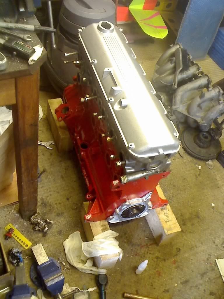
got the dummy build donor bottom end from a mate of mine, stripped it down, cleaned everything up and gave a few bits a coat of paint.
got some clay out and bannged it between the piston and the head to measure the clearance to the head around the squish band.
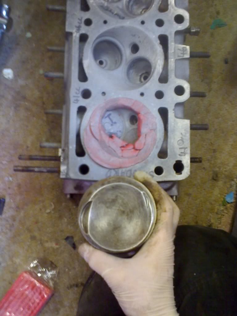
found it was about even all the way around and at ~1.71mm which im led to believe is too much, as it wont quench the charge properly and can hold end gas.
took a mould of the chamber to work from
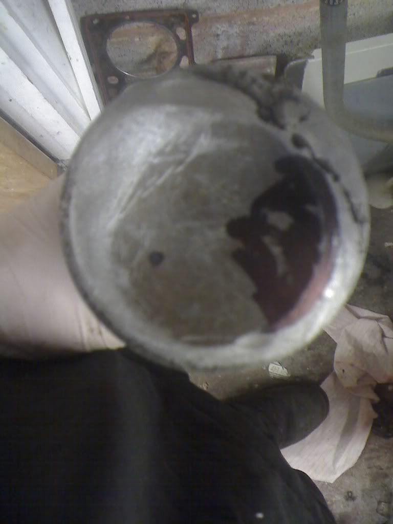
measured a piston up and found theres a hell of a lot of meat on these stock e30 pistons,
ill get the figues up when i have my note pad to hand.
what it ment was i could take some meat off the top to get them to work in a stroker.
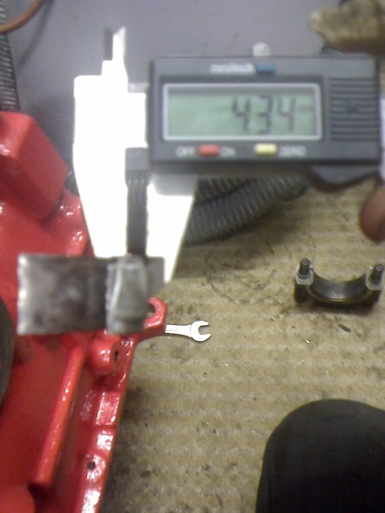
as dans pulling the crank and pistons from a b28 for me as we speak i had to improvise a little to put the piston at the same height, que a 4.5mm bearing spacer.
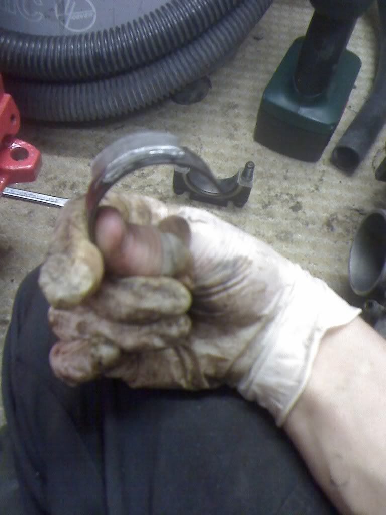
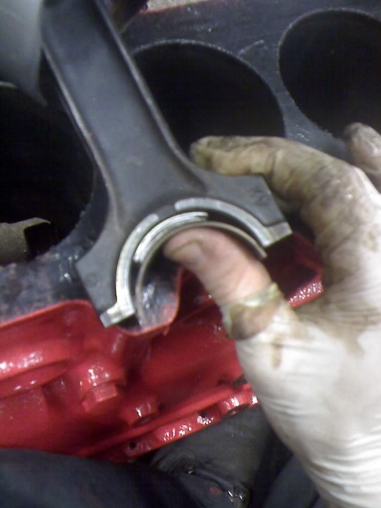
it was actually 4.34mm after being squashed flat and glued in place so ill have to take a little more off the pistons later on but meh, it will do as a test.
in actual fact i made a 3mm spacer for the 2.7 stroke as well and did a 2.7 piston first...
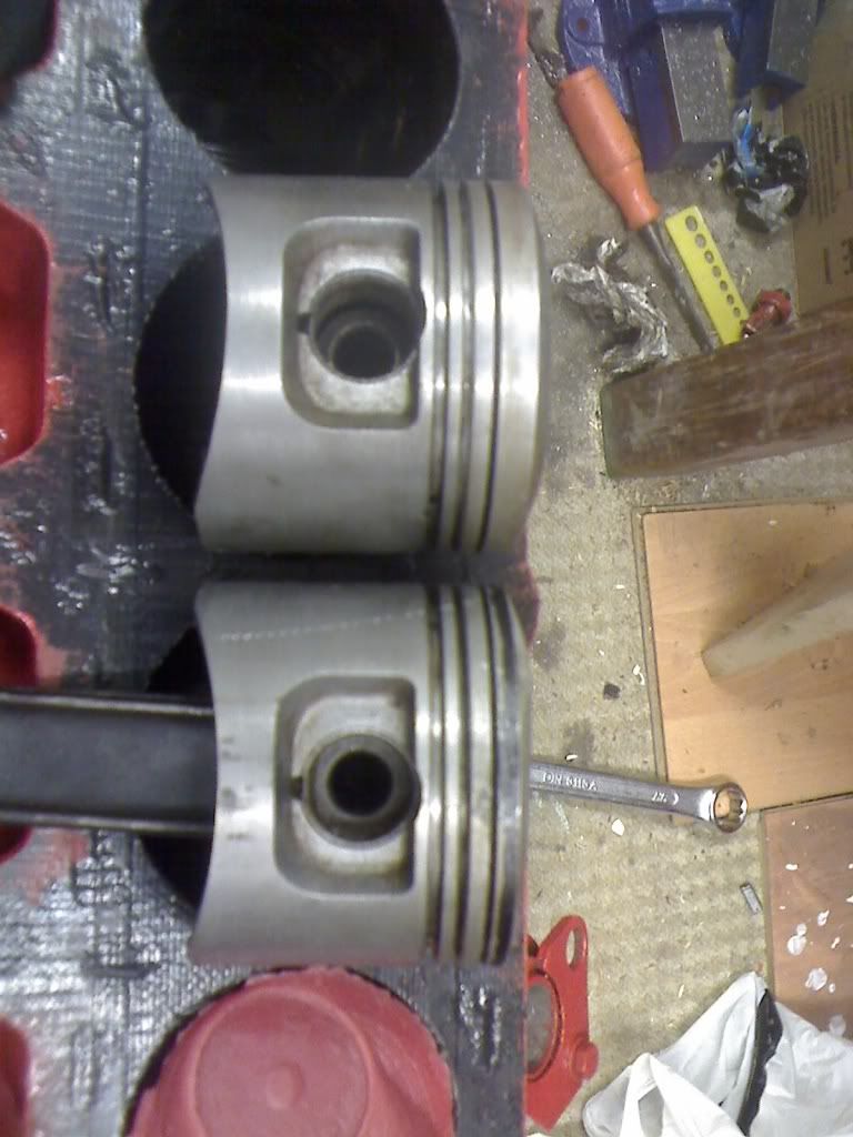
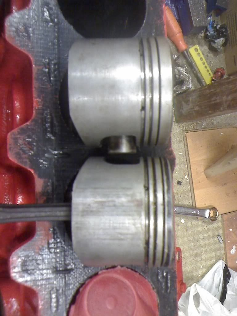
more than enough meat on these to go down 3mm, once iv tested a set and pit the valve pockets in (both of which should be fine, i have been doing my homework on these) there should be no more need for anyone to ever get 2mm decked from there blocks.
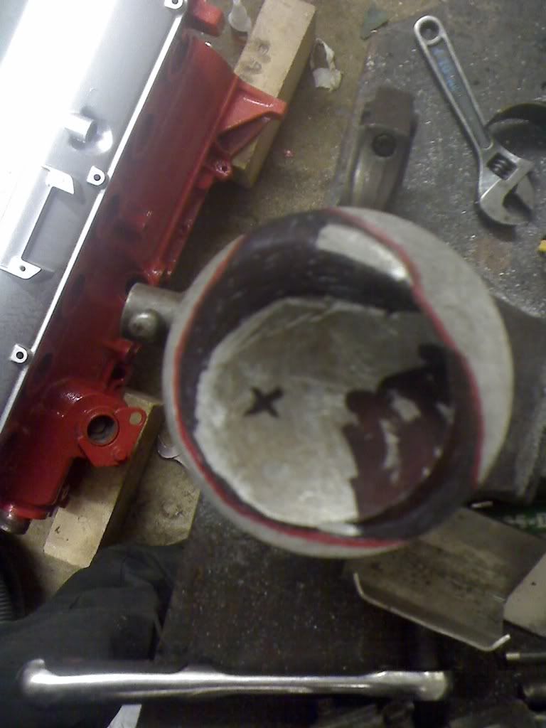
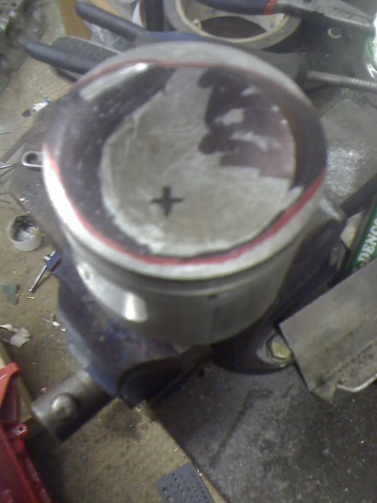
once that was done i went full bore at the 4.34mm chop.
from the top of my head the top ring land was 8.something mm thick, and 0.5mm needs removing from the head clearance to leave 1.2mm squish distance
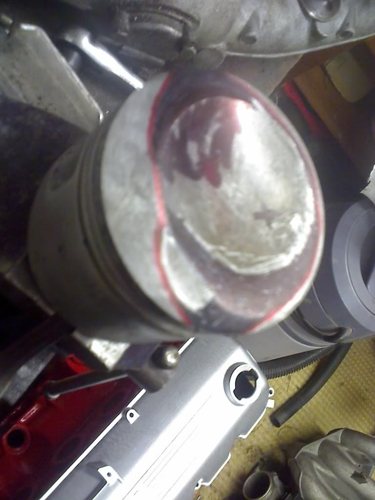
the top ring land is now 3.85mm thick which im led to believe will be fine and a thermal coat will allow the thing to last as well, the bowl in the centre of the piston is still standard thickness.
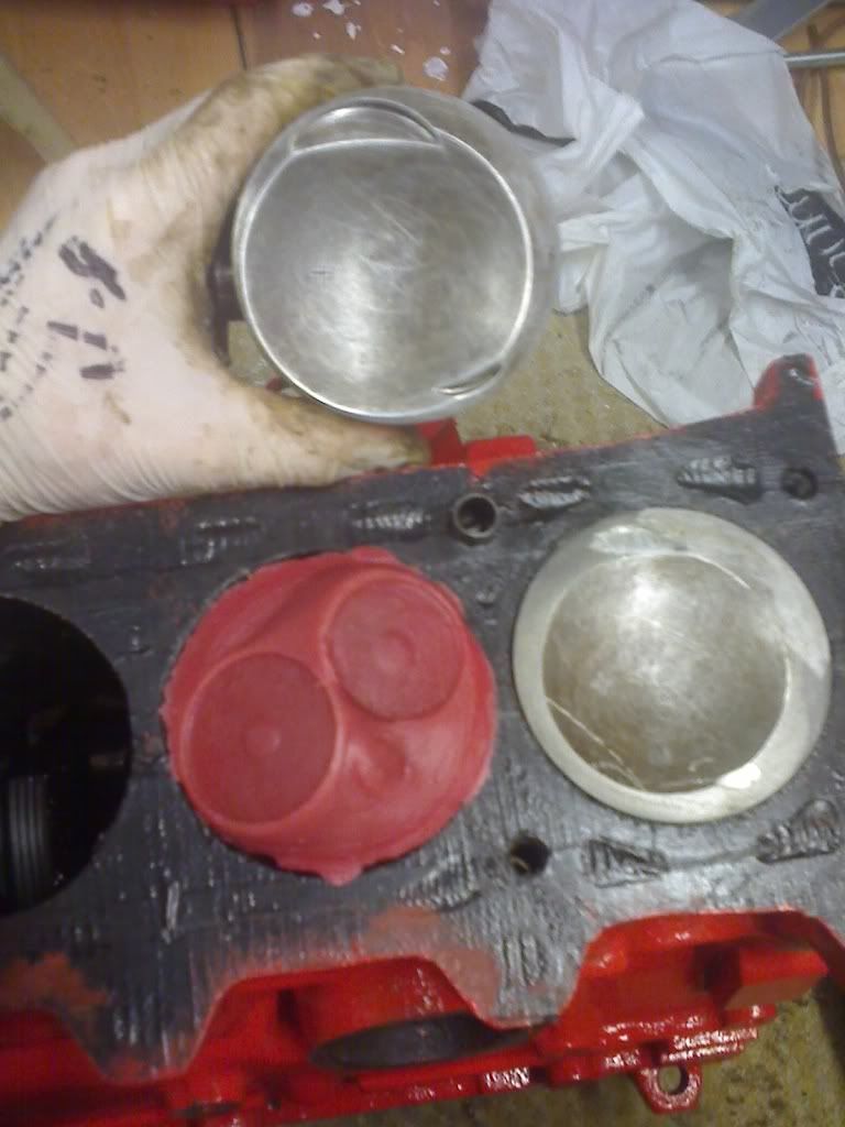
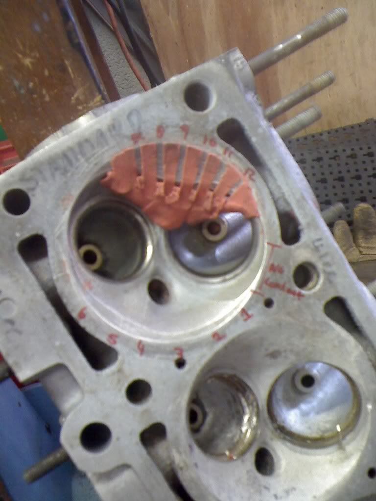
i need to reduce the ridge around the edge as at the moment this one is making 12:1 compression
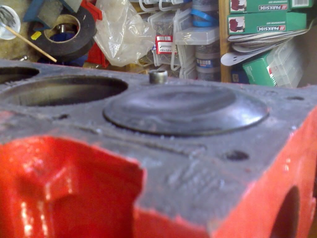
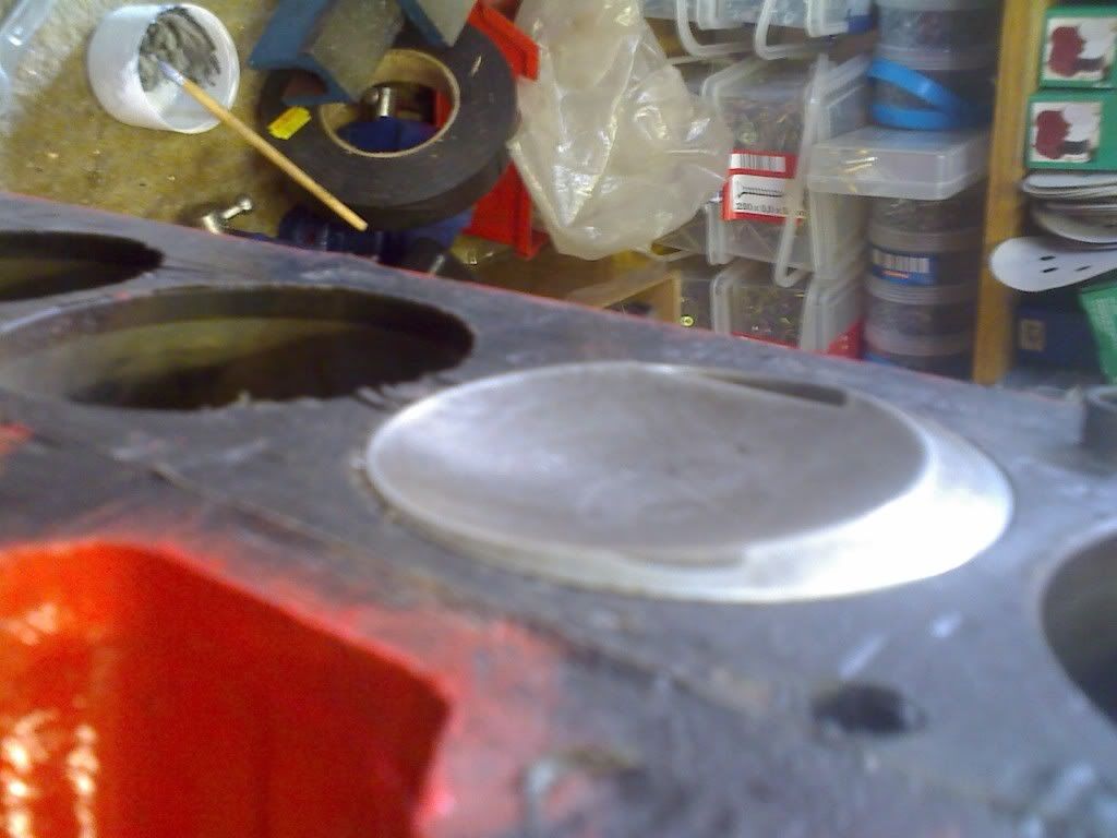
the red line around the top of the piston here indicates what bits of the piston are at risk of contact with the head and the bits in the black are dead meat that can be worked about however to give the desired combustion chamber shape and CR.
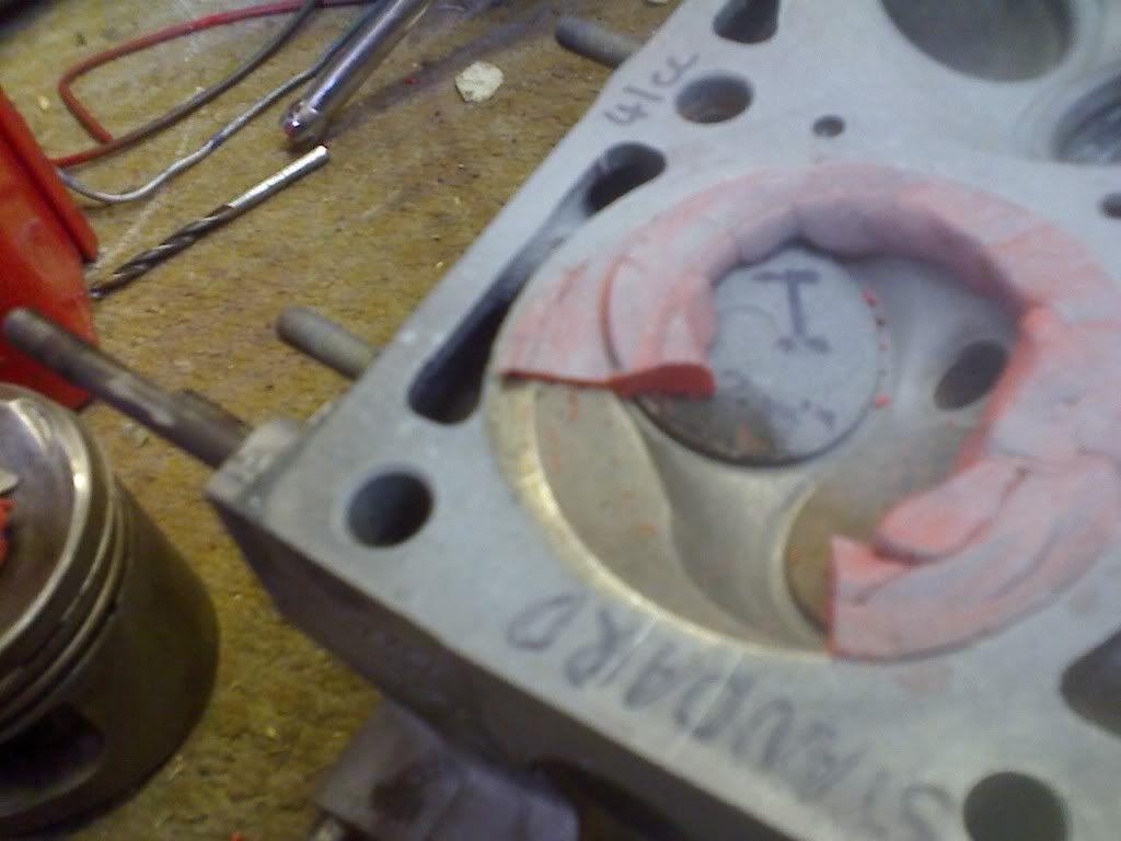
again bunged some clay in there and checked the squish
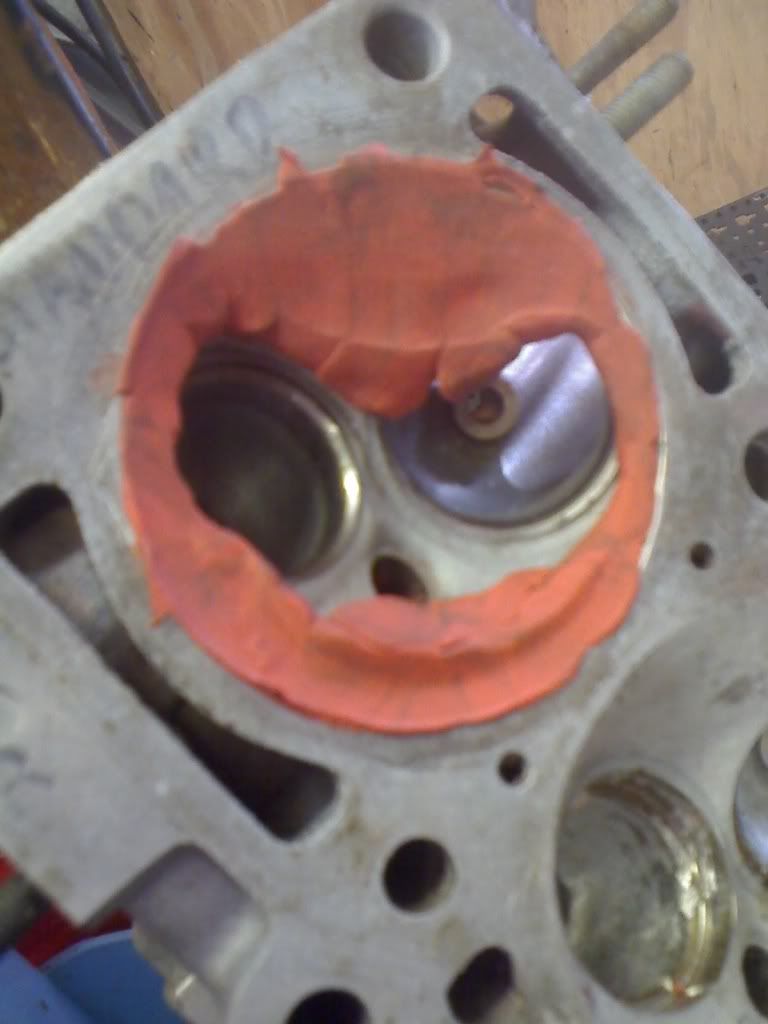
as you can see its now shoving the clay well out into the chamber compared to the before.
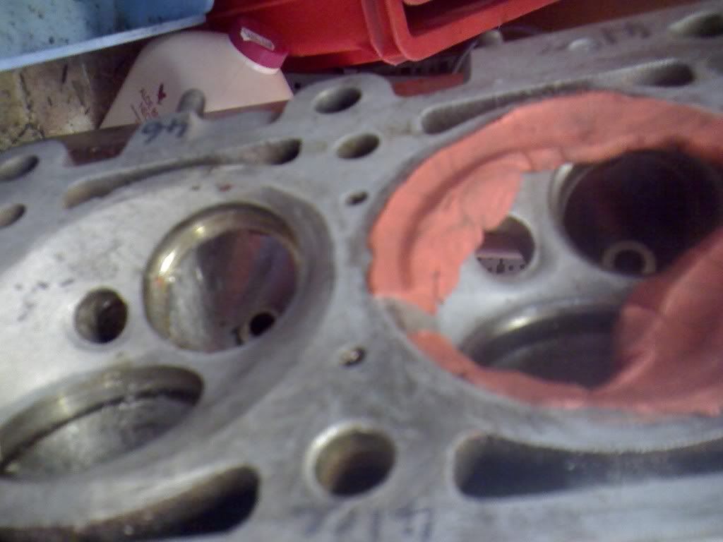
iv got the measurements of the clearance written down as well but not to hand, its around 1.1mm at the mo so a little more of a skim will be needed.
next post will be a 731 head, different seats and valves and the porting taken to its logical extreme conclusion, both of which will be tested this week.
got the dummy build donor bottom end from a mate of mine, stripped it down, cleaned everything up and gave a few bits a coat of paint.
got some clay out and bannged it between the piston and the head to measure the clearance to the head around the squish band.
found it was about even all the way around and at ~1.71mm which im led to believe is too much, as it wont quench the charge properly and can hold end gas.
took a mould of the chamber to work from
measured a piston up and found theres a hell of a lot of meat on these stock e30 pistons,
ill get the figues up when i have my note pad to hand.
what it ment was i could take some meat off the top to get them to work in a stroker.
as dans pulling the crank and pistons from a b28 for me as we speak i had to improvise a little to put the piston at the same height, que a 4.5mm bearing spacer.
it was actually 4.34mm after being squashed flat and glued in place so ill have to take a little more off the pistons later on but meh, it will do as a test.
in actual fact i made a 3mm spacer for the 2.7 stroke as well and did a 2.7 piston first...
more than enough meat on these to go down 3mm, once iv tested a set and pit the valve pockets in (both of which should be fine, i have been doing my homework on these) there should be no more need for anyone to ever get 2mm decked from there blocks.
once that was done i went full bore at the 4.34mm chop.
from the top of my head the top ring land was 8.something mm thick, and 0.5mm needs removing from the head clearance to leave 1.2mm squish distance
the top ring land is now 3.85mm thick which im led to believe will be fine and a thermal coat will allow the thing to last as well, the bowl in the centre of the piston is still standard thickness.
i need to reduce the ridge around the edge as at the moment this one is making 12:1 compression
the red line around the top of the piston here indicates what bits of the piston are at risk of contact with the head and the bits in the black are dead meat that can be worked about however to give the desired combustion chamber shape and CR.
again bunged some clay in there and checked the squish
as you can see its now shoving the clay well out into the chamber compared to the before.
iv got the measurements of the clearance written down as well but not to hand, its around 1.1mm at the mo so a little more of a skim will be needed.
next post will be a 731 head, different seats and valves and the porting taken to its logical extreme conclusion, both of which will be tested this week.
2.8 development thread http://www.e30zone.net/modules.php?name ... c&t=170822
m3.3.1 m20 thread - now running, chip needed - any volunteers?
http://www.e30zone.net/modules.php?name ... =viewtopic&
m3.3.1 m20 thread - now running, chip needed - any volunteers?
http://www.e30zone.net/modules.php?name ... =viewtopic&
-
Ant
- Retired Team Member

- Posts: 10496
- Joined: Tue Dec 21, 2004 11:00 pm
- Location: PD+E dept :D
Nice update
12:1 would be a nice static CR

12:1 would be a nice static CR
Product Development and Endurance for Delphi.
Original performance chips, original works not unlicensed copies Email FTW
Original performance chips, original works not unlicensed copies
-
HairyScreech
- Engaged to the E30 Zone
- Posts: 6265
- Joined: Sun Jan 21, 2007 11:00 pm
12:1 on lpg or e85. 
ill try and get down to a more sociable 10.5:1, theres still plenty of meat on the piston, i cant believe how thick they were up top.
the height of the top ring land is my biggest worry, how well this will work for a 2.8 depends greatly on the quality of the alu in the piston, the ceramic coat will do it untold favours but if the alu isnt up to it then the top ring land could hammer out.
the biggest problem with a lot of this is its all "may, might, if, possibly" as theres no hard and fast rules. one piston may be fine with a 3mm ring land and another may need a 5mm minimum.
and theres no easy way to tell which is which, as it depends on material grade, burn rate and pattern, fuel grade, chamber shape, head thermal conductivity, heat loss to the bore walls, oil squirts or not,
it is possible to calculate it but i wouldnt like to bet my nuts on it.
what is dose mean is forget decking your block 2mm and having a vernier cam pully, get the pistons machined for higher comp, better squish and less side thrust.
2.8 development thread http://www.e30zone.net/modules.php?name ... c&t=170822
m3.3.1 m20 thread - now running, chip needed - any volunteers?
http://www.e30zone.net/modules.php?name ... =viewtopic&
m3.3.1 m20 thread - now running, chip needed - any volunteers?
http://www.e30zone.net/modules.php?name ... =viewtopic&
-
m_jermyn
- E30 Zone Team Member
- Posts: 4208
- Joined: Sat Mar 14, 2009 11:00 pm
- Location: Sydney Australia Mate
So have you finished porting the head? I have read this whole thread but I thought you had more to do.. Whats the best thing to do to a 885 then?
-
Ant
- Retired Team Member
- Posts: 10496
- Joined: Tue Dec 21, 2004 11:00 pm
- Location: PD+E dept :D
One thought came to me late in the night(sad sad sad b'stard I know)
all the flowbench data suggests the port will flow more(almost a given) however could you flow test a complete intake from TB to combustion chamber to get a "real world" flow rate ?
Flowbench is not my thing hence the Q, if all the pumping restrictions are removed from the engine itself, would there be more to find I wonder, I've found no data on this anywhere.
be a 'mare to flow 220CFM @ the head but only 190 with all the intake upstream.
885s respond well to a tickle of the ports and some relief in the valve throat area immediately behind the valve seat, the actual port runners are not too bad at all (IMHO of course)
Keep the updates coming Mr Screech
Re the top ring, on some major CR Harleys they drill gas holes in the crown to push the upper ring in full contact with the cyl wall,allegedly assist with temp contol as the gas pressure is equal on both sides, might be worth a google ? reasoning could well be BS but I have seen the pistons in the flesh, holes defo there.
all the flowbench data suggests the port will flow more(almost a given) however could you flow test a complete intake from TB to combustion chamber to get a "real world" flow rate ?
Flowbench is not my thing hence the Q, if all the pumping restrictions are removed from the engine itself, would there be more to find I wonder, I've found no data on this anywhere.
885s respond well to a tickle of the ports and some relief in the valve throat area immediately behind the valve seat, the actual port runners are not too bad at all (IMHO of course)
Keep the updates coming Mr Screech
Re the top ring, on some major CR Harleys they drill gas holes in the crown to push the upper ring in full contact with the cyl wall,allegedly assist with temp contol as the gas pressure is equal on both sides, might be worth a google ? reasoning could well be BS but I have seen the pistons in the flesh, holes defo there.
Product Development and Endurance for Delphi.
Original performance chips, original works not unlicensed copies Email FTW
Original performance chips, original works not unlicensed copies
-
johnt0709
- E30 Zone Addict
- Posts: 2291
- Joined: Mon Nov 06, 2006 11:00 pm
- Location: West of Scotland
Man - this is so way over my head and hopefully Im not alone - what is it we are trying to achieve here and will it result in manufacturing of items, for purchase, to improve performance.
Im not the thickest but this is just not my thing - if it can improve performance of my E30 then im interested - but can someone explain what the end goal is (in simple terms).
Im not the thickest but this is just not my thing - if it can improve performance of my E30 then im interested - but can someone explain what the end goal is (in simple terms).
Phase I - Bodywork Complete
http://www.e30zone.net/modules.php?name ... by+restore
Phase II - 2.8 stroker- Complete
Project II - 325 Motorsport Cabriolet Restoration.
http://www.e30zone.net/modules.php?name ... by+restore
Phase II - 2.8 stroker- Complete
Project II - 325 Motorsport Cabriolet Restoration.
-
Ant
- Retired Team Member
- Posts: 10496
- Joined: Tue Dec 21, 2004 11:00 pm
- Location: PD+E dept :D
to build a stroker engine using the longer 135mm con rods for less rod angle and hopefully more power and TQ
TBh I've done these both ways, 3 HP in it and the 130mm rod came out tops with same cam and CR in both engines( indeed same everything )
I'm open minded though, everything can be improved upon
TBh I've done these both ways, 3 HP in it and the 130mm rod came out tops with same cam and CR in both engines( indeed same everything )
I'm open minded though, everything can be improved upon
Product Development and Endurance for Delphi.
Original performance chips, original works not unlicensed copies Email FTW
Original performance chips, original works not unlicensed copies
-
e21Jason
- E30 Zone Addict
- Posts: 2040
- Joined: Tue Jan 11, 2005 11:00 pm
- Location: Dubai, UAE
Intresting,
Just thinking I have a 323i crank which is 76.8 v 75mm throw so I could drop in the 323i crank and use the 325i rods and pistons and get away with a high CR, might just need a tad thicker MLS gasket, and using the tripple weber's and long duration cam a high static CR would not be that bad
Jason
Just thinking I have a 323i crank which is 76.8 v 75mm throw so I could drop in the 323i crank and use the 325i rods and pistons and get away with a high CR, might just need a tad thicker MLS gasket, and using the tripple weber's and long duration cam a high static CR would not be that bad
Jason
BMW e21 track car supercharged s14 cage and fabrication by www.chizfab.com
Z3M Coupe for sale
69 Alfa spyder
Z3M Coupe for sale
69 Alfa spyder
-
Ant
- Retired Team Member
- Posts: 10496
- Joined: Tue Dec 21, 2004 11:00 pm
- Location: PD+E dept :D
Sounds Awesome Jason , get the spanners out, 2554 cc iirc.
O/T you don't have any E21 323i fuel tanks spare do you, given up searching down here.
O/T you don't have any E21 323i fuel tanks spare do you, given up searching down here.
Product Development and Endurance for Delphi.
Original performance chips, original works not unlicensed copies Email FTW
Original performance chips, original works not unlicensed copies
-
Nay
- Channel Island Crew
- Posts: 3988
- Joined: Wed Aug 13, 2008 11:00 pm
I'm with you here. Following the thread, and understanding the main points but some of the explainations, figures and methods used are over my head entirely.I imagine more are following than posting, I get the ideas but its way beyond my maths.
I'll stick to making software n' websites and then throw my money at a potential conclusion to this topic
Keep it up Screech!

Uni is killing the project.
-
TouringTash
- E30 Zone Team Member
- Posts: 3804
- Joined: Mon Jun 28, 2010 11:00 pm
- Location: Kent
'..............and then throw my money at a potential conclusion to this topic Very Happy'
Noooooo
Its all about doing it ya-self.
Keep this hush hush but I'm with you Nay
Noooooo
Its all about doing it ya-self.
Keep this hush hush but I'm with you Nay
-
daimlerman
- **BANNED**
- Posts: 15968
- Joined: Mon Feb 27, 2006 11:00 pm
- Location: Grumpy Old Man
Hopefully,fellow thicko's,the end result will be a set of drawings/photo's that we can follow and understand.
Fair play to the OP for sharing his university education with us,as a taxpayer it is good to learn that it is not all waste!
I am right in 'thinking' that a high static CR is largely overcome by valve overlap?
So a potential 12.1 will run on pump petrol?
Fair play to the OP for sharing his university education with us,as a taxpayer it is good to learn that it is not all waste!
I am right in 'thinking' that a high static CR is largely overcome by valve overlap?
So a potential 12.1 will run on pump petrol?
Youth is wasted on the young.
-
HairyScreech
- Engaged to the E30 Zone
- Posts: 6265
- Joined: Sun Jan 21, 2007 11:00 pm
right, quite a few responses this morning, dont you all have jobs to do? 
lets do this in order....
which i will be doing early next week.
im going to have to flow the no1 chamber with the manifold and then ill use the 731 head which has 3 unmolested chambers to see if theres any difference between each of the runners.
im fairly sure the manifold wont flow well enough, its just not got large enough runners and there far to long to do much up top. so initially the engine will run on the stock manifold and a proper one will be built later on, perhaps with throttles.
2. im not sure what you mean by " if all the pumping restrictions are gone, will there be more to find", in terms of pumping losses its always a compromise between gas velocity and flow, and i dont think its really possible on a 2v to be over valved.
3. your right on the 885, the best flow so far has been from narrowing the guide and working the port upwards a little either side, cutting the lower side of the floor to make the short side wider and working the back of the bowl a bit, to raise the height of the bowl roof a touch.
i have a feeling from speaking to a few people that the seat could do with a multi angle cut as said earlier in this, im going to sort out a 30/45/70 and a 30/45/65/75 cut and see what we get.
4. iv seen what you refer to, its something that is used in drag pistons quite a bit, the intention is to prevent ring flutter and help stop the seat hammering out, there like vertical ports just behind the top ring.
its worth looking into but im not 100% its of much use here.
the aim is really to take a proper look at the m20, its not a bad engine, but it is far from optimized, im using a lot of this for my third year uni project now (well i might still change my mind) so some things are going to seem a little pointless to the real world.
if you take a look about half way down the first page there is a few questions im going to try and answer and a list of things i think need looking at.
they really come down to improving the head flow, increasing the compression and the thermal efficiency, reducing the reciprocating mass, reducing oil and windage losses, tons of other stuff but iv got a memory like a sieve.
i dont know if im going to actually build any more once im done with this, it all depends on the quality of the results and the final product.
if things work well i might knock a couple of batches of pistons up, perhaps a couple of heads and maybe build a few complete engines if people want to pay for the work.
you should have 1.7mm to the head with a stock 2.5 piston, which by all accounts is a little slack, with 1.8mm extra stroke then you would only need to skim 1.2mm off the piston to get the thing back to a nice clearance of 1.1mm,
this is all done using a crushed standard gasket, i think its an elring one but ill check, ill also stick a vernier across the gasket and check the thickness,
if your going to use an mls then your pistons are going to end up closer to begin with so more will need to come off the crown.
the only reason i have a 12:1 static atm is the bowl is reduced as the edge of the piston in taken down, what i have done is cut the piston down around the 21 deg angle.
the reduction in the bowl also makes the thing a bit more thermally efficient. so thats a win win.
if your taking less off the edge of the piston then your static cr will be lower as there will still be more bowl.
the pics further back show this better than i can explain.
lets do this in order....
nope, its just im back from uni for the summer and the flow bench is in uni, so theres only so much i can do until i pop back up to hit the bench again.m_jermyn wrote:So have you finished porting the head? I have read this whole thread but I thought you had more to do.. Whats the best thing to do to a 885 then?
which i will be doing early next week.
1. yep, iv got a full intake and throttle body to put on the bench asap, and a 731 head with a 42mm intake valve crammed in and ported out a bit.Ant wrote:One thought came to me late in the night(sad sad sad b'stard I know)
all the flowbench data suggests the port will flow more(almost a given) however could you flow test a complete intake from TB to combustion chamber to get a "real world" flow rate ?
Flowbench is not my thing hence the Q, if all the pumping restrictions are removed from the engine itself, would there be more to find I wonder, I've found no data on this anywhere.
885s respond well to a tickle of the ports and some relief in the valve throat area immediately behind the valve seat, the actual port runners are not too bad at all (IMHO of course)
Keep the updates coming Mr Screech
Re the top ring, on some major CR Harleys they drill gas holes in the crown to push the upper ring in full contact with the cyl wall,allegedly assist with temp contol as the gas pressure is equal on both sides, might be worth a google ? reasoning could well be BS but I have seen the pistons in the flesh, holes defo there.
im going to have to flow the no1 chamber with the manifold and then ill use the 731 head which has 3 unmolested chambers to see if theres any difference between each of the runners.
im fairly sure the manifold wont flow well enough, its just not got large enough runners and there far to long to do much up top. so initially the engine will run on the stock manifold and a proper one will be built later on, perhaps with throttles.
2. im not sure what you mean by " if all the pumping restrictions are gone, will there be more to find", in terms of pumping losses its always a compromise between gas velocity and flow, and i dont think its really possible on a 2v to be over valved.
3. your right on the 885, the best flow so far has been from narrowing the guide and working the port upwards a little either side, cutting the lower side of the floor to make the short side wider and working the back of the bowl a bit, to raise the height of the bowl roof a touch.
i have a feeling from speaking to a few people that the seat could do with a multi angle cut as said earlier in this, im going to sort out a 30/45/70 and a 30/45/65/75 cut and see what we get.
4. iv seen what you refer to, its something that is used in drag pistons quite a bit, the intention is to prevent ring flutter and help stop the seat hammering out, there like vertical ports just behind the top ring.
its worth looking into but im not 100% its of much use here.
dont worry, a lot of this was over my head as well until i started reading, theres a huge amount of info out there, a lot of it is on the small block v8s but were working with similar size bores and pistons with similar weights so its still applicable.johnt0709 wrote:Man - this is so way over my head and hopefully Im not alone - what is it we are trying to achieve here and will it result in manufacturing of items, for purchase, to improve performance.
Im not the thickest but this is just not my thing - if it can improve performance of my E30 then im interested - but can someone explain what the end goal is (in simple terms).
the aim is really to take a proper look at the m20, its not a bad engine, but it is far from optimized, im using a lot of this for my third year uni project now (well i might still change my mind) so some things are going to seem a little pointless to the real world.
if you take a look about half way down the first page there is a few questions im going to try and answer and a list of things i think need looking at.
they really come down to improving the head flow, increasing the compression and the thermal efficiency, reducing the reciprocating mass, reducing oil and windage losses, tons of other stuff but iv got a memory like a sieve.
i dont know if im going to actually build any more once im done with this, it all depends on the quality of the results and the final product.
if things work well i might knock a couple of batches of pistons up, perhaps a couple of heads and maybe build a few complete engines if people want to pay for the work.
sounds doable, would give you a 2.6 and might give a nice little kick, perhaps take it over the 190hp mark.e21Jason wrote:Intresting,
Just thinking I have a 323i crank which is 76.8 v 75mm throw so I could drop in the 323i crank and use the 325i rods and pistons and get away with a high CR, might just need a tad thicker MLS gasket, and using the tripple weber's and long duration cam a high static CR would not be that bad
Jason
you should have 1.7mm to the head with a stock 2.5 piston, which by all accounts is a little slack, with 1.8mm extra stroke then you would only need to skim 1.2mm off the piston to get the thing back to a nice clearance of 1.1mm,
this is all done using a crushed standard gasket, i think its an elring one but ill check, ill also stick a vernier across the gasket and check the thickness,
if your going to use an mls then your pistons are going to end up closer to begin with so more will need to come off the crown.
the only reason i have a 12:1 static atm is the bowl is reduced as the edge of the piston in taken down, what i have done is cut the piston down around the 21 deg angle.
the reduction in the bowl also makes the thing a bit more thermally efficient. so thats a win win.
if your taking less off the edge of the piston then your static cr will be lower as there will still be more bowl.
the pics further back show this better than i can explain.
2.8 development thread http://www.e30zone.net/modules.php?name ... c&t=170822
m3.3.1 m20 thread - now running, chip needed - any volunteers?
http://www.e30zone.net/modules.php?name ... =viewtopic&
m3.3.1 m20 thread - now running, chip needed - any volunteers?
http://www.e30zone.net/modules.php?name ... =viewtopic&
-
hennie
- E30 Zone Newbie
- Posts: 29
- Joined: Sat Nov 24, 2007 11:00 pm
on my stroker im using 320 rods block is decked .3mm head is .8mm lower than stock my quench clearance came to .8mm compression ratio about 11.3:1 if i remember correctly ,had to pocket the pistons for valves 2mm deeper as the valves were touching the pistons
on my 320 rods i cut oil squirter slots like the 325 rods
my cam timing is still spot on the marks without a vernier pulley
my head has some material gone in no 1 chamber so the head is not perfect im interested in your gas flow tricks and would do the backup head i picked up to your specks my old stroker made 148kw on the fly with no 4 piston running on broken rings this motor is one with new 20 thou oversize pistons fitted haven't dynod it yet to see what it makes now
keep up the good work if this works out then the spare block in my garage will get done the same
-
HairyScreech
- Engaged to the E30 Zone
- Posts: 6265
- Joined: Sun Jan 21, 2007 11:00 pm
sounds about right. thats around 202hp, which is about right.
your comp sounds far to high for a 320 rod and stock piston shape, 9.5 something is a stock piston crown.
mines only so high as the bowl has been reduced due to skimming them.
update:
just got a pair of heads for free from mick_318is. absolute legend for that one.
just stripped them down and got all of the head bits i have out and have ended up with this!
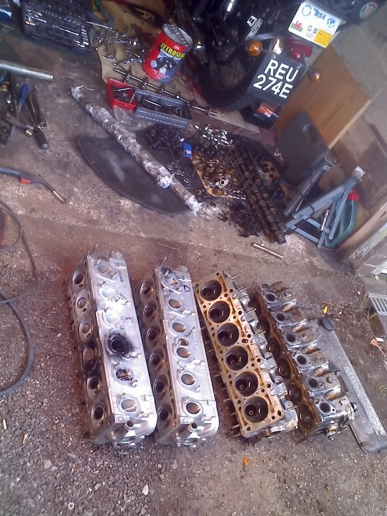
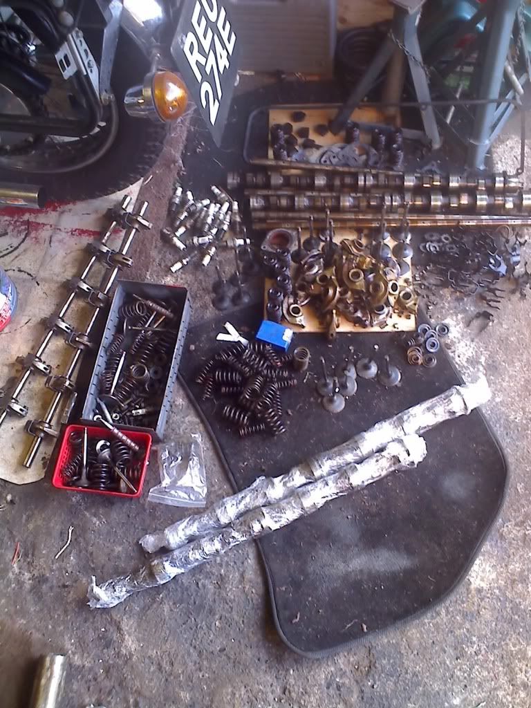
bring on the cleaning and blueprinting.
gunna be a long evening i think.
job after than is to make myself some valve seat cutting tools.
iv got the option of pay £15 a seat, pay ~£150 for numan ones or make my own. hmm hard choice.
your comp sounds far to high for a 320 rod and stock piston shape, 9.5 something is a stock piston crown.
mines only so high as the bowl has been reduced due to skimming them.
update:
just got a pair of heads for free from mick_318is. absolute legend for that one.
just stripped them down and got all of the head bits i have out and have ended up with this!
bring on the cleaning and blueprinting.
gunna be a long evening i think.
job after than is to make myself some valve seat cutting tools.
iv got the option of pay £15 a seat, pay ~£150 for numan ones or make my own. hmm hard choice.
2.8 development thread http://www.e30zone.net/modules.php?name ... c&t=170822
m3.3.1 m20 thread - now running, chip needed - any volunteers?
http://www.e30zone.net/modules.php?name ... =viewtopic&
m3.3.1 m20 thread - now running, chip needed - any volunteers?
http://www.e30zone.net/modules.php?name ... =viewtopic&
-
HairyScreech
- Engaged to the E30 Zone
- Posts: 6265
- Joined: Sun Jan 21, 2007 11:00 pm
status update,
iv weighed the 30 something rockers i have and seleceted the lightest 12. iv removed all casting marks and sharp angles on them in a big to keep them in one piece. pic to follow.
currently working on weight matching the rockers, theres quite a varaiation in them mind.
one thing i did notice was there are two kinds of rockers, the b20 ones and the b25 ones, the b25 rockers have an extra little lump on the side to beef them up a bit, ill take a pic of this later on as show what i mean.
also got me a nice big bundle of stuff on thursday morning.
an m52b28TU crank with shells, m52b28 rods and pistons, and a set of 140mm rods.
a 36kg package thanks to dan, the postie wasnt impressed.
2.8 development thread http://www.e30zone.net/modules.php?name ... c&t=170822
m3.3.1 m20 thread - now running, chip needed - any volunteers?
http://www.e30zone.net/modules.php?name ... =viewtopic&
m3.3.1 m20 thread - now running, chip needed - any volunteers?
http://www.e30zone.net/modules.php?name ... =viewtopic&