rix313 wrote:Oops I totaly forgot about that Geoff sorry

The plate is made up and fitted now if you'd like to have a look at my project thread

I saw the plate in your thread but thought you might still want a proper CAD drawing of it for your file. If you still want one, mail me your sketch. Otherwise it's less work for me, so no worries.
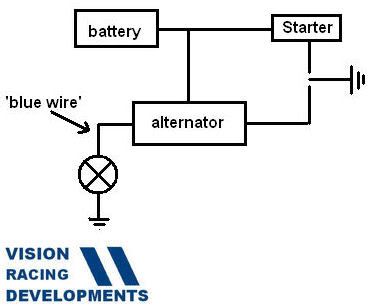
rix313 wrote:I wasn't aware of this sensory cable. I routed all the cables that were connected to the battery terminal, to the junction box which is connected to the single large cable I have going to the back of the car is this going to be a problem? There was the alternator/starter cable and then two smaller ones crimped into one eyelet which I imagine are for the fuse box? There is a small blue wire also connected to the alternator but I guessed this is for the dash charge warning light? or is it one in the same?
Yeh, it sounds like that blue wire. I made up my wire loom from wire salvaged from an E36 loom, so my wire colours are all different yours, well actually my alternator is different as well, but they all work pretty much the same. Ideally that wire should be routed to your battery in the back of your car. This is what I did on mine when I shifted the battery to the back. The reason for this is so that your alternator knows exactly what your battery voltage is. If you connect it somewhere else up front, this voltage will be slightly lower depending upon how much current your engine, wipers, lights etc are drawing through the cable that goes back to the battery. The thicker this cable, the lower the volt drop, and the less of a problem it is. You should, however, be aware that when you are pulling a lot of current down that cable your alternators output voltage could push well higher than 14V, so its best to route that "sense" wire straight to the battery. This is how I did mine. The good news though is that the "sense" wire draws very little current, and so can be quite thin.
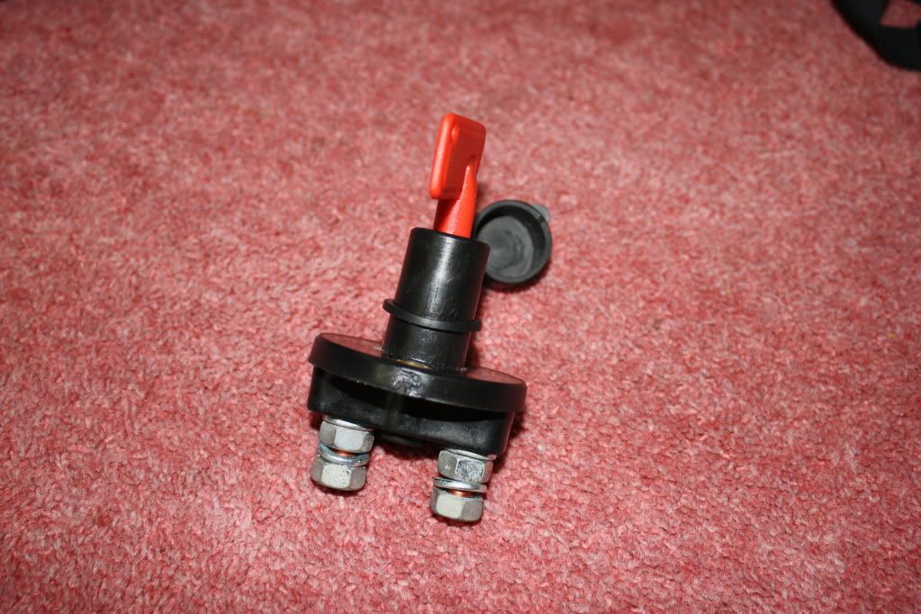
rix313 wrote:Can you/how do you test the amp rating of the switch using a multi-meter?
Unfortunately this is not possible with a multimeter. Possibly you can trace the part back to the supplier and find out? I don't think you'll draw more than 40A through it with your engine, wipers and lights all on. And I assume you are not carting a boot load if ICE around the track

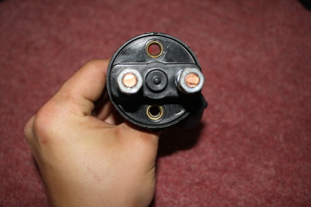
. Do your regs require that you route your starter motor through your switch as well? If this is the case then make sure you have one of the
really heavy duty switches as your starter can pull a good 50 to 80A just by itself.