
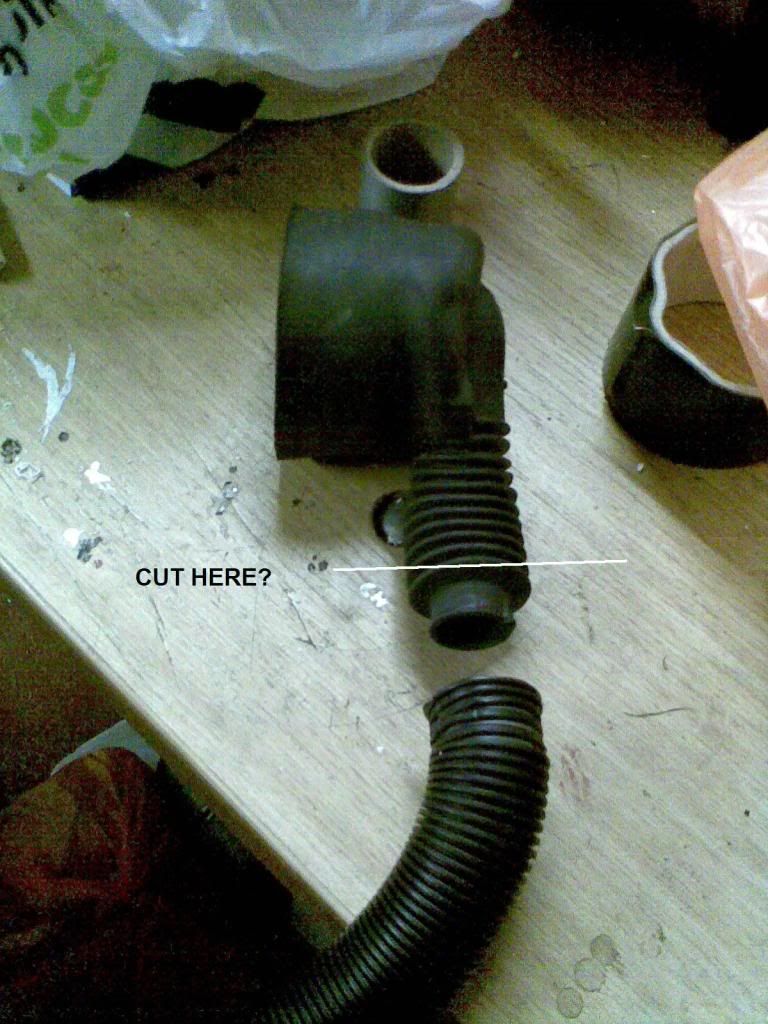
The rubber boot from the filler doesn't seal down onto 8mm copper pipe or a flexible filling hose. The rubber boot seals down onto a length of 30mm flexible vent hose, with the filling pipe, of whichever type, running inside of it.
Once the vent hose goes through the boot floor, it ends, and can either be sealed in place, or use purpose designed flanges for the job.
The idea is, that whatever part of the system decides to leak, it will vent to the underside of the car.
A polyurethane sealant (PU) is the best to use, and is similar to the OE undercoating on E30s'.
LPG Installation Help
Moderator: martauto

I have got the same rubber boot as the one on that website but the entery for it is only 25mm. I have some of that 30mm vent hose with the flange for it. Could I put the rubber boot in hot water and stretch it over the 30mm vent hose or should I cut the boot higher up so that the entery will be larger and then zip tie it up?
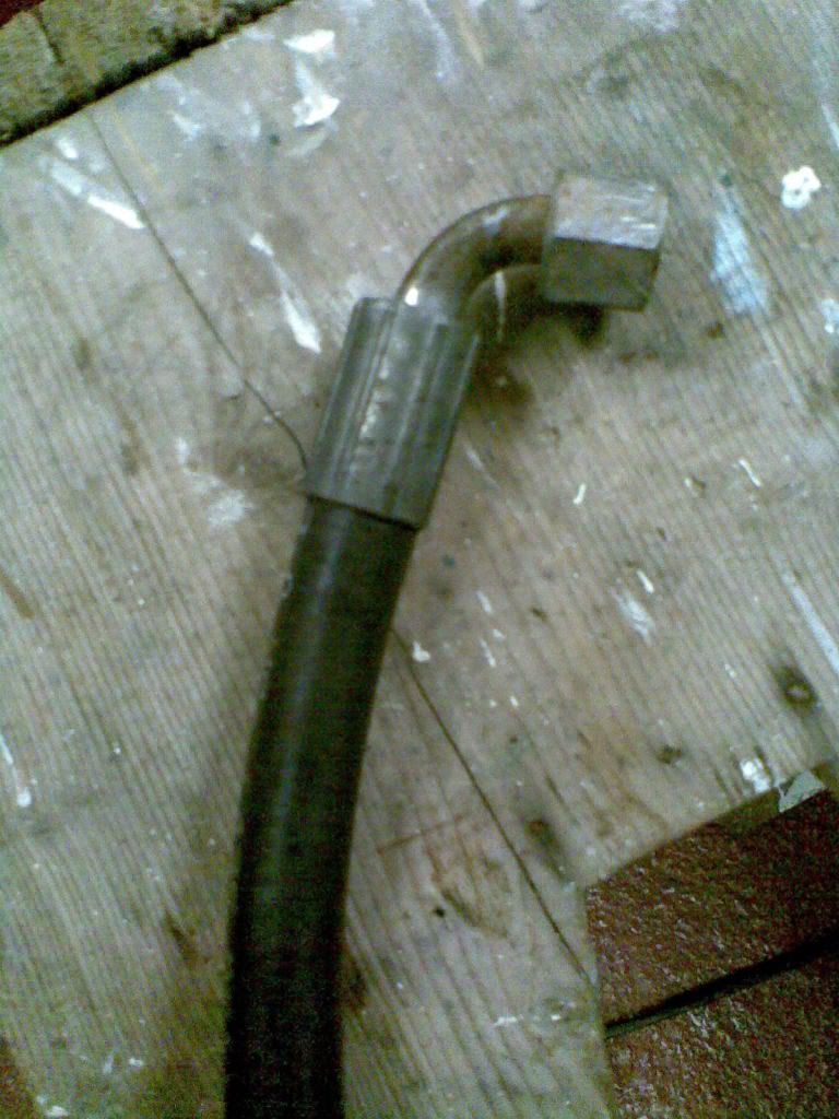
This is the original pipe that went through the boot.
Cheers
This is the original pipe that went through the boot.
Would Seam sealer do the job though as I have just bought some?A polyurethane sealant (PU) is the best to use, and is similar to the OE undercoating on E30s'.
Cheers
-
Brianmoooore

- E30 Zone Team Member

- Posts: 49358
- Joined: Mon Jan 10, 2005 11:00 pm
AFAIK, vent hose only comes in one size, so it should fit your rubber boot. Stretch it.
Don't see any reason why a few coats of seam sealer wouldn't do the job.
(Just looked at some of the prices on that site. They certainly know how to charge!!)
Don't see any reason why a few coats of seam sealer wouldn't do the job.
(Just looked at some of the prices on that site. They certainly know how to charge!!)
(Just looked at some of the prices on that site. They certainly know how to charge!!)
Yes, I thought that too. The scrapyard gave me that filler and boot for free. That site charges £45 for it!
So hot water and stretch it over, if not as it seamed pritty tight before, Could I cut the boot like above?
Cheers
Yes, I thought that too. The scrapyard gave me that filler and boot for free. That site charges £45 for it!
So hot water and stretch it over, if not as it seamed pritty tight before, Could I cut the boot like above?
Cheers
-
Brianmoooore
- E30 Zone Team Member
- Posts: 49358
- Joined: Mon Jan 10, 2005 11:00 pm
As long as it's all sealed together, and stays together, it's fine.
ok, tank is in, Im going to start putting the copper pipe in. How much will I need? Will 2m of 8mm and 5m of 6mm be enough?
Also, could some one please tell me the way they laid the 6mm pipe from the tank to the engine bay because I have noticed there is loads of rules about where it can go and that it has to be 250mm from the exhaust at all times. Pics would be helpful
Cheers
Also, could some one please tell me the way they laid the 6mm pipe from the tank to the engine bay because I have noticed there is loads of rules about where it can go and that it has to be 250mm from the exhaust at all times. Pics would be helpful
Cheers
-
Brianmoooore
- E30 Zone Team Member
- Posts: 49358
- Joined: Mon Jan 10, 2005 11:00 pm
Has to be 250mm from the exhaust OR shielded from it. My 6mm line roughly follows the existing fuel and brake lines.
Use a bit of string to gauge how much of each pipe you need.
Use a bit of string to gauge how much of each pipe you need.
Measured it up and ordered 6m and 2m.
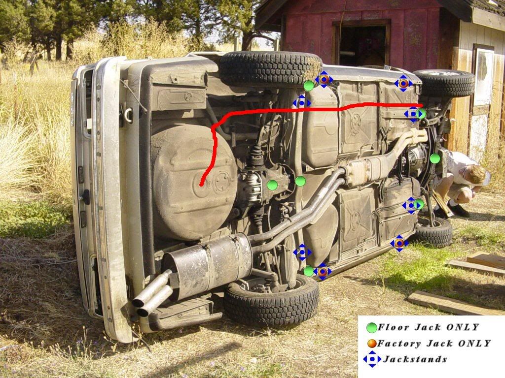
Where did you run your pipe compared to where the red line is on the photo? Or, could you draw out where you ran yours and then I could follow as I cant get my head round the COP11 document and I dont want to do it wrong.
Cheers
Where did you run your pipe compared to where the red line is on the photo? Or, could you draw out where you ran yours and then I could follow as I cant get my head round the COP11 document and I dont want to do it wrong.
Cheers

that picture is brilliant.
My install crossed the silencer right at the back where it is coldest, then over the swinging arm thus following th fuel and brake pipes (alot of zip ties) to the engine bay. I wanted it to be on the side that doesnt have the exhaust manifold
My install crossed the silencer right at the back where it is coldest, then over the swinging arm thus following th fuel and brake pipes (alot of zip ties) to the engine bay. I wanted it to be on the side that doesnt have the exhaust manifold


Mine follows the blue line (roughly), straight forwards then to the petrol filler, forwards then across the rear beam above the diff, using the beam as a heat shield, then follows the fuel lines forwards.. The electrics follow the same route
The red line would bring it out in the engine bay near the hottest part of the exhaust
Cheers for that mate. That was what I was looking for . Should be getting the pipe today so will start doing that. Did you drill into the floor pan and use a self tapper with a p-clip to hold the pipe up? And can I cable tie the wiring onto the gas pipe?
Cheers
Cheers
-
Brianmoooore
- E30 Zone Team Member
- Posts: 49358
- Joined: Mon Jan 10, 2005 11:00 pm
Don't know what happened to my post of where I ran the pipes, but it was fairly close to the blue line above.
Nearly every "professional" instal I've ever seen has the wiring cable tied to the pipe, but I would never do this. The underside of a car is no place for electrical wiring!
Run it back the LH sill inside, with the main car loom, or under the carpet on top of the transmission tunnel.
Nearly every "professional" instal I've ever seen has the wiring cable tied to the pipe, but I would never do this. The underside of a car is no place for electrical wiring!
Run it back the LH sill inside, with the main car loom, or under the carpet on top of the transmission tunnel.
pretty much, it folowed the blue route exactly except it didnt do that peak over the diff, just over the nearside half shaft.jon_d_h wrote:So you came out under the wheel well and above the heat shield of exhaust or over the exhaust pipe tips by the rear bumber?My install crossed the silencer right at the back where it is coldest
Cheers
Cheers
Ok, back to mixers, still finding it hard to find 1. Would this one do? It looks to be the right size and is made for the same airbox. The only thing is where the inlet pipe is. Could this be mounted on the outside of the airbox but still between the afm or would it go in the air box?
Cheers
Ok, back to mixers, still finding it hard to find 1. Would this one do? It looks to be the right size and is made for the same airbox. The only thing is where the inlet pipe is. Could this be mounted on the outside of the airbox but still between the afm or would it go in the air box?
Cheers
-
Brianmoooore
- E30 Zone Team Member
- Posts: 49358
- Joined: Mon Jan 10, 2005 11:00 pm
Insert link here: ?????
-
Brianmoooore
- E30 Zone Team Member
- Posts: 49358
- Joined: Mon Jan 10, 2005 11:00 pm
Could be worth a try. It should fit between the air filter box and the AFM OK. No idea if the bolt holes will line up, but it won't hurt to drill new ones if needed.
If you have trouble getting it to idle properly, then the centre is too big, but you'll just have to experiment.
Pity it's bundled with the cat flap, as that's too big for a 325 AFM.
If you have trouble getting it to idle properly, then the centre is too big, but you'll just have to experiment.
Pity it's bundled with the cat flap, as that's too big for a 325 AFM.
He said he would sell it seperaptly to the backfire valve. The hole centres should line up because it is for the same airflow meter. There is this one with a smaller venturi and is for the same afm:
http://cgi.ebay.co.uk/Vauxhall-BMW-316- ... 240%3A1318
Which I should I go for?
Cheers
http://cgi.ebay.co.uk/Vauxhall-BMW-316- ... 240%3A1318
Which I should I go for?
Cheers
-
Brianmoooore
- E30 Zone Team Member
- Posts: 49358
- Joined: Mon Jan 10, 2005 11:00 pm
The venturi size is always a bit of a compromise between top end power and an adequate idle. Go for the bigger one, and see how it goes.
-
Brianmoooore
- E30 Zone Team Member
- Posts: 49358
- Joined: Mon Jan 10, 2005 11:00 pm
You may have to fit the mixer outside of the airbox. This will push the airbox another 20mm towards the front of the car.
Im using one from a F**d escrote zetec, any 4 wire one should do though.
If your getting one from a scrapyard rummage try to get a BOSCH one, rather than a newer looking cheapo
You can also get both sides of the plug and socket so it can look a bit neater.
If your getting one from a scrapyard rummage try to get a BOSCH one, rather than a newer looking cheapo
You can also get both sides of the plug and socket so it can look a bit neater.
Update
Tank is fitted in the boot, pipe from the tank to the solinoid in the engine bay is in, wiring in and leonardo above glove box with wiring going through the bulkhead. Bracket for vaporisor is fitted and ready for vaporisor.
Do i cut the heater water pipes where they enter the car and put 2 T pieces in for the water to the vaporisor?
Also, where is the best place for the TPS wire to be taped into for the leonardo?
Cheers
-
Brianmoooore
- E30 Zone Team Member
- Posts: 49358
- Joined: Mon Jan 10, 2005 11:00 pm
Heater pipes can be teed into about 3"- 4" from the heater stub pipes, or, if you are happy to lose the full cold function of the heater, you can disable the electric heater valve (unplug it, or pull the inline fuse near it), and connect the vapouriser between the top heater stub pipe and the tee hose.
TPS connection can be anywhere you chose between the TPS and the ECU. Nowhere is particularly easier than anywhere else.
P.S: I was looking through a box of LPG fittings today for something, and came across a mixer that had come from a M20B25, so I measured the venturi size. It is 33mm.
TPS connection can be anywhere you chose between the TPS and the ECU. Nowhere is particularly easier than anywhere else.
P.S: I was looking through a box of LPG fittings today for something, and came across a mixer that had come from a M20B25, so I measured the venturi size. It is 33mm.
Ok thanks. Would you think about selling the mixer? . The dealer selling the one on ebay still hasnt got back to me about it. Are the heater stub pipes the ones going through the bulk head? T into both of them? and does it matter which goes into which on the vaporisor?
Im doing the wiring now and have some questions:
1) does the TPS brown/blue go through the c101 plug as there is not one there in mine? I cant find where to tap into it
2)Where can I find the red/white for the petrol injectors where the 2 yellows go in series with it?
3)When checking the 2 yellows, they were open circuit. I would have thought that they would be closed circuit when the leonardo is not pluged in. Is this how it should be?
4)With the tank level sender, I have a Black, red and white on the plug to the multivalve. And have a Green and a White from the Leonardo. Which go to which?
Cheers
-
Brianmoooore
- E30 Zone Team Member
- Posts: 49358
- Joined: Mon Jan 10, 2005 11:00 pm
Mixer's not for sale, I'm afraid; it's got a future appointment with one of my 325's!
Stub pipes are as you say, and you can tee into both of them, connecting the vapouriser in parallel, which will result in a slightly reduced maximum heater output, or connect in in series as detailed in my last post, and not be able to turn the heater completely off in summer. Doesn't matter which way the pipes go to the vapouriser, but consider how air will vent from it.
1) TPS doesn't go anywhere near the C101 - it goes between the TPS and the ECU, so you will have to pick the wire out of the loom somewhere along the route.
2)The red white wire has a solder joint in it, where it splits to feed the ICV and the injectors.
You can either intercept it somewhere around the injector loom plug and socket under the inlet manifold, OR cut it at the DME relay, and run a fresh feed to the idle valve.
3)???? With the Leonardo unplugged, the yellows won't be closed circuit, since they won't be connected to anything at the plug end!
4) The Leonardo is able to be configured to work with several different types of level sender, by different wiring connections and by software changes.
The white wire is always used, but the green can either be connected separately, connected directly to the white, or left open circuit.
Since you have a three wire sensor, it seems likely you need the seperate connections, but your three wire sensor colours don't match up with those in the Leonardo instructions.
One (black?) will be earth, but the others, I can't say for sure.
So the red/white wire runs from the fuse box or ECU to the solder joint, splits and one goes to the ICV and one to the injectors. So I cant break into it before the solder joint as I only want to break the supply to the injectors and not the ICV?2)The red white wire has a solder joint in it, where it splits to feed the ICV and the injectors.
You can either intercept it somewhere around the injector loom plug and socket under the inlet manifold, OR cut it at the DME relay, and run a fresh feed to the idle valve.
Sorry, unsure what is ment here. How air will vent from what?Doesn't matter which way the pipes go to the vapouriser, but consider how air will vent from it.
Cheers
-
Brianmoooore
- E30 Zone Team Member
- Posts: 49358
- Joined: Mon Jan 10, 2005 11:00 pm
The red/white wire starts at the DME relay (white one, under the cover by the air filter). You can break it here, as long as you run a new feed to the ICV.
The vapouriser needs to be able to vent the air that's inside it when you fill the cooling system, the same as any other part of the system.
The vapouriser needs to be able to vent the air that's inside it when you fill the cooling system, the same as any other part of the system.
Ok, So what you recomend I do. I have the 70 litre tank still. Can the multivalve from that go on my 40 litre tank? It has 2 wires ( a white and Black). The 70 litre tank is 280mm tall and my new tank is alot shorter?4) The Leonardo is able to be configured to work with several different types of level sender, by different wiring connections and by software changes.
The white wire is always used, but the green can either be connected separately, connected directly to the white, or left open circuit.
Since you have a three wire sensor, it seems likely you need the seperate connections, but your three wire sensor colours don't match up with those in the Leonardo instructions.
One (black?) will be earth, but the others, I can't say for sure.
Cheers
-
Brianmoooore
- E30 Zone Team Member
- Posts: 49358
- Joined: Mon Jan 10, 2005 11:00 pm
I suggest you experiment with the three wire sensor. Probably black = earth, red = green and green = white, but, assuming black is earth, there's only two possibilities.
Any chance just the level sender will swap over? They are not normally part of the multivalve - just screwed onto the outside and magnetically coupled.
Any chance just the level sender will swap over? They are not normally part of the multivalve - just screwed onto the outside and magnetically coupled.
The vapouriser needs to be able to vent the air that's inside it when you fill the cooling system, the same as any other part of the system.
Sorry, stil unsure what you mean? I havent done anything with the cooling system before apart from top it up . There is 2 inlets for the cooling for the vaporisor, one at the top and one at the bottom.
I think I will do it this way. I have had a look at the white relay and there is 2 white/red wires on the same crimp. One is about 4mm so is very think and the other is about 1mm. As they are both joined in the relay, I am unsure where each one goes. Do you know whis one goes where?The red/white wire starts at the DME relay (white one, under the cover by the air filter). You can break it here, as long as you run a new feed to the ICV.
Cheers
Also, The mixer:
http://cgi.ebay.co.uk/ws/eBayISAPI.dll? ... TQ:GB:1123
The holes are as pictured and do not line up with what my mixer is. The coordinates are (0;0)(82;0) (82;25) (82;50) (0;25) (0;50) mm. The holes are correctly space lenght ways as it is suposed to be 82mm. But there are 3 holes spaced out vertically 25mm apart which is not right. Could I drill new holes in between these? I really want to get this as it is the only thing realy stoping me now.
Cheers
-
Brianmoooore
- E30 Zone Team Member
- Posts: 49358
- Joined: Mon Jan 10, 2005 11:00 pm
Can't see any reason why not, as long as you don't leave any gas leaks.jon_d_h wrote: Could I drill new holes in between these? I really want to get this as it is the only thing realy stoping me now.