
Twin Seq. Dry sumping for beginners :D
Moderator: martauto
-
driftmonkey

- E30 Zone Newbie

- Posts: 249
- Joined: Sat Sep 15, 2007 11:00 pm
- Location: Portsmouth/Southern Italy
mind blowing! think of the costs in man hrs a company would charge!! Where did you learn to weld? and was your tig welder expensive? I'm getting myself a mig welder and hoping to teach myself, had a go a couple of times myself, hardest bit I found was setting the welder up, took me ages.
-
Turbo-Brown
- Boost Junkie
- Posts: 4705
- Joined: Tue Feb 15, 2005 11:00 pm
- Location: Aldershot, Hants
Cheers dude, do wonder what it would've cost to get someone professional to do all this from time to time 
I taught myself to TIG weld (which is probably why I'm not all that great at it ) The main thing is concentrating on three things at once and getting yourself and/or the work into a position that lets you hold the torch and filler comfortably. Think the unit cost about £1200 or so.
Learned the MIG from my ol' man, the setup is important and so is the quality of the machine you use. Gasless ones are useless IMO, as are machines with no fan cooling for the transformer. Then the other potential source of irritation is the wire feed which wastes lots of wire when it broaches
Which welder did you have in mind to buy?
I taught myself to TIG weld (which is probably why I'm not all that great at it
Learned the MIG from my ol' man, the setup is important and so is the quality of the machine you use. Gasless ones are useless IMO, as are machines with no fan cooling for the transformer. Then the other potential source of irritation is the wire feed which wastes lots of wire when it broaches
Which welder did you have in mind to buy?
-
driftmonkey
- E30 Zone Newbie
- Posts: 249
- Joined: Sat Sep 15, 2007 11:00 pm
- Location: Portsmouth/Southern Italy
Its a secondhand one of a guy i work with, 120 turbo, think its made by sealy. mig with big gas bottle, arc reactive mask, £120, just waiting on him checking it over to make sure its all ok before he sells it, not been used for afew months.
I'm hoping to do some stainless welding, abit of ally aswell as the usual bodywork stuff. Currently getting the bits together to turbo a citroen ax(i know but it was cheap)
I'm hoping to do some stainless welding, abit of ally aswell as the usual bodywork stuff. Currently getting the bits together to turbo a citroen ax(i know but it was cheap)
-
Turbo-Brown
- Boost Junkie
- Posts: 4705
- Joined: Tue Feb 15, 2005 11:00 pm
- Location: Aldershot, Hants
Be interested to see how you get on with the MIG when ali welding. Never tried it myself, think the wire feed becomes even more important with the bendy wendy ali wire.
Made a wee bit more progress today, albeit very slowly.
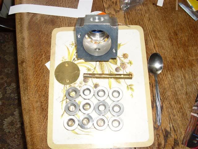
Made some bearing holders and pressed the little needle rollers into them:
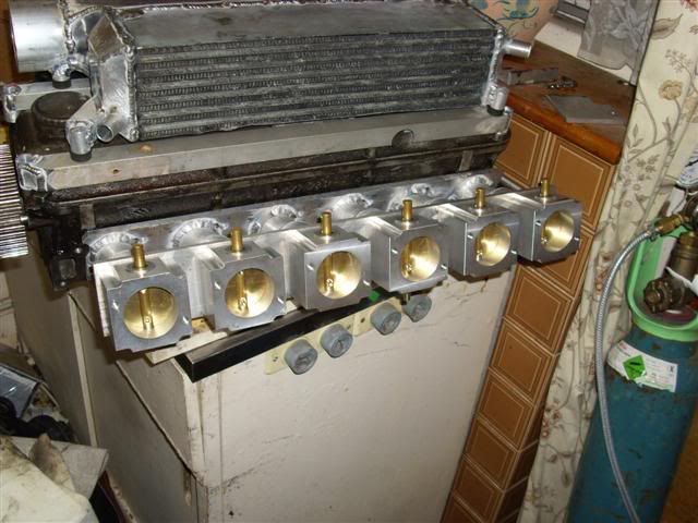
Had a bit of a trial fit:
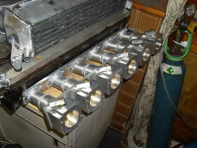
And before getting bored for the day, started on the linkage arms:
Made a wee bit more progress today, albeit very slowly.
Made some bearing holders and pressed the little needle rollers into them:
Had a bit of a trial fit:
And before getting bored for the day, started on the linkage arms:
-
Andy335Touring
- Married to the E30 Zone

- Posts: 7144
- Joined: Sun Jan 09, 2005 11:00 pm
- Location: Long Eaton,Nottingham
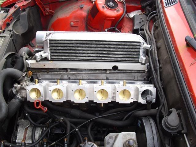
Those TB housings look chunky, i bet the complete set(plenum/tb's/etc) up will weigh a bit ?
Will you use some sort of bracket from the engine to the bottom of the TB's to take some of the weight like the M30 manifold ?
The braket attaches to the engine mount.

Will you use some sort of bracket from the engine to the bottom of the TB's to take some of the weight like the M30 manifold ?
The braket attaches to the engine mount.
-
Turbo-Brown
- Boost Junkie
- Posts: 4705
- Joined: Tue Feb 15, 2005 11:00 pm
- Location: Aldershot, Hants
Hadn't occured to me to be honest, but it's a good idea!
Thinking about it, I guess the M20 manifold is braced to the rocker cover too.
Will add the brace to my list of things to do
Thinking about it, I guess the M20 manifold is braced to the rocker cover too.
Will add the brace to my list of things to do
-
hoshy
- E30 Zone Wiki Guru

- Posts: 4118
- Joined: Tue Jan 18, 2005 11:00 pm
- Location: Munich
Maybe you can hack up the m42 one you've got lying aroundTurbo-Brown wrote:Hadn't occured to me to be honest, but it's a good idea!
Thinking about it, I guess the M20 manifold is braced to the rocker cover too.
Will add the brace to my list of things to do
E46 M3 CSL but dreaming of another E30.
-
jkarran
- E30 Zone Regular

- Posts: 327
- Joined: Thu Jan 12, 2006 11:00 pm
- Location: Isle of Man
Hey, this is looking pretty close to being done  Just the plenuum and a thousand and one little bits left to do
Out of interest, why have you pressed the bearings into carriers then the carriers into the TBs, why not fit them direct, do they retain an O-ring between TB and carrier?
And what's the step in the OD of the inlet runners for, do the TB's slide into the runners rather than bolt direct to the flange? When I first saw them I thought you might be going for variable length inlet tracts and adding another scarey level of sophistication
I'm in awe of how much work you're putting into this but it'll be worth it twice over when it runs
jk
E30 320i Rally Turd - Usually broken
E24 635Csi - Rotting in peace for now
E34 540i - Daily driver
Blown R1 Striker - In progress
E24 635Csi - Rotting in peace for now
E34 540i - Daily driver
Blown R1 Striker - In progress
-
Turbo-Brown
- Boost Junkie
- Posts: 4705
- Joined: Tue Feb 15, 2005 11:00 pm
- Location: Aldershot, Hants
Think the engine side of things is coming along nicely (once I source another set of super-strong rods......although might yet stick with the M52 ones).
Just got linkages, plenums, charge cooling, crank case ventilation, exhaust system, actuators, bodywork, suspension, 5 stud conversion, carbon panels and so on to do.
Oh, that's more than I thought now I've written it down
The step is there because I machined these translators to take me from 48mm-38mm out of solid, and then welded them to the 38mmID pipes which run to the head. No variable runners for me! That's would be scarily complicated!
Still umming and aahing over the control for all these actuators. Have even thought about using a megasquirt for each one so that it's fully 3D mappable against either pressure and revs or throttle and revs. Would be bloody expensive, but would also give the very best control over the actuators which is what I really need I think.
Hmmmmmmmmmm.
Just got linkages, plenums, charge cooling, crank case ventilation, exhaust system, actuators, bodywork, suspension, 5 stud conversion, carbon panels and so on to do.
Oh, that's more than I thought now I've written it down
The step is there because I machined these translators to take me from 48mm-38mm out of solid, and then welded them to the 38mmID pipes which run to the head. No variable runners for me!
Still umming and aahing over the control for all these actuators. Have even thought about using a megasquirt for each one so that it's fully 3D mappable against either pressure and revs or throttle and revs. Would be bloody expensive, but would also give the very best control over the actuators which is what I really need I think.
Hmmmmmmmmmm.
-
Turbo-Brown
- Boost Junkie
- Posts: 4705
- Joined: Tue Feb 15, 2005 11:00 pm
- Location: Aldershot, Hants
Oh yeah, re the bearings: I designed the throttle shells to accept a ball bearing but have decided to have a try with the needly rollers which is why I needed the adaptors. There will be some seals going in too at some point under the bearing holders.
-
Turbo-Brown
- Boost Junkie
- Posts: 4705
- Joined: Tue Feb 15, 2005 11:00 pm
- Location: Aldershot, Hants
Aah bollocks to it, going to waste some more work and just buy a set of sealed ball races rather than experiment with the needle rollers and proprietary seals. You live and learn eh
-
jkarran
- E30 Zone Regular
- Posts: 327
- Joined: Thu Jan 12, 2006 11:00 pm
- Location: Isle of Man
jk
E30 320i Rally Turd - Usually broken
E24 635Csi - Rotting in peace for now
E34 540i - Daily driver
Blown R1 Striker - In progress
E24 635Csi - Rotting in peace for now
E34 540i - Daily driver
Blown R1 Striker - In progress
-
Turbo-Brown
- Boost Junkie
- Posts: 4705
- Joined: Tue Feb 15, 2005 11:00 pm
- Location: Aldershot, Hants
It's quite hard to let go of an idea that you've been clinging to isn't it?! Even when you know you'll be better off in the end.
Been a bit of a slow weekend progress wise. Was going to try and finish off the charge cooler so I fitted the cooler and throttles in the car so I could have a play with the runners. There really is a deceptive amount of free space under the E30's bonnet as it doesn't come anywhere near the cooler, even at the front!
I'd thought I could use 135degree 48mm Samco hoses for the runners. Turns out I was quite wrong and that I need more like 180 degree bends so that put paid to the idea of completing the cooler this week
So anyway, thoughts turned to something I hadn't been looking forward to but needed to get done before completing the cooler which is the trumpets.
I bought a lump of 3"dia mild steel to turn down as a former:
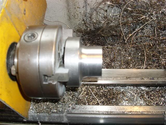
Then cut 6 lengths of 2"dia ali tube, lubed them up with some EP80, put each one over the former in turn and gave them a squeeeeeeeeeze:
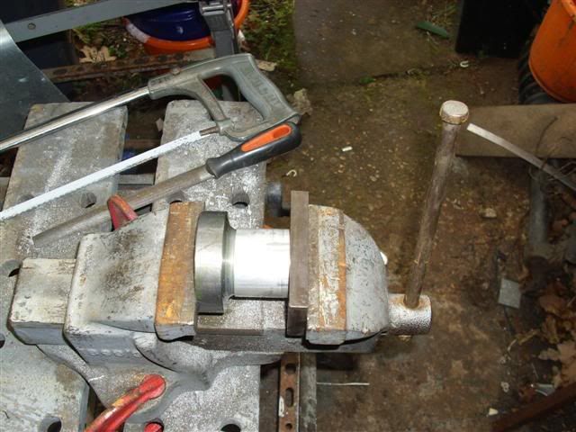
Which gives these lovely trumpets which I can weld into the cooleras outlets from the plenum into the Samco runners
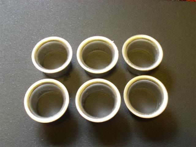
Really pleased with how they've come out, although it was SOOOOOO boring making the former!
Been a bit of a slow weekend progress wise. Was going to try and finish off the charge cooler so I fitted the cooler and throttles in the car so I could have a play with the runners. There really is a deceptive amount of free space under the E30's bonnet as it doesn't come anywhere near the cooler, even at the front!
I'd thought I could use 135degree 48mm Samco hoses for the runners. Turns out I was quite wrong and that I need more like 180 degree bends so that put paid to the idea of completing the cooler this week
So anyway, thoughts turned to something I hadn't been looking forward to but needed to get done before completing the cooler which is the trumpets.
I bought a lump of 3"dia mild steel to turn down as a former:
Then cut 6 lengths of 2"dia ali tube, lubed them up with some EP80, put each one over the former in turn and gave them a squeeeeeeeeeze:
Which gives these lovely trumpets which I can weld into the cooleras outlets from the plenum into the Samco runners
Really pleased with how they've come out, although it was SOOOOOO boring making the former!
-
Turbo-Brown
- Boost Junkie
- Posts: 4705
- Joined: Tue Feb 15, 2005 11:00 pm
- Location: Aldershot, Hants
Aah awesome news!
Just had a reply from Emerald about the PWM outputs available. I'd asked them whether it would be possible to have a couple more added or if they could make me a little mappable control box as I need at least 3 programmable PWM outputs.
Apparently they're soon to add another two into the K3 which can be had with a firmware and software update.
All of which means I should be able to use just the Emerald to control all the functions of my engine
Good news everyone! (said professor Farnsworth!)
-
Turbo-Brown
- Boost Junkie
- Posts: 4705
- Joined: Tue Feb 15, 2005 11:00 pm
- Location: Aldershot, Hants
Think the rods dilemma has resolved itself.
Going to go with the Manley rods from VAC motorsport, and looks like they can supply ARP main stud kits plus a nice head stud kit which I'm particularly pleased with as I don't like head bolts!
Another weight has been taken off my mind as they can supply a MLS head gasket which will suit the 85mm bore.
-
tbmw
- E30 Zone Regular
- Posts: 681
- Joined: Mon Jan 10, 2005 11:00 pm
- Location: weston super mare
I am in awe at your ability to work out what you need then just machine it up and away you go
this will be amazing when it's done
this will be amazing when it's done

A clear conscience is a sign of a bad memory
-
appletree
- E30 Zone Addict
- Posts: 3482
- Joined: Fri Jan 20, 2006 11:00 pm
- Location: Retford
Out of intrest how important is it to use the trumpets in the inlet? i didnt use any in mine first time round just ground off the sharp edge, i'am going to try and incorporate them in the design this time round though.

You should never underestimate the predictability of stupidity
M42 Supercharged 285bhp + M3 6speed box
-
Turbo-Brown
- Boost Junkie
- Posts: 4705
- Joined: Tue Feb 15, 2005 11:00 pm
- Location: Aldershot, Hants
Cheers TBMW
I believe that the trumpet increases the effective area of the throat of the runner. If you imagine the air flowing along a flat surface and then falling into the runner over a 90degree sharp bend, it won't follow the wall of the runner down. If you have a nice rad for it to follow though, the air should follow the runner side down.
Can't hurt to have the radiused inlet anyway!
-
oakey
- E30 Zone Addict
- Posts: 4891
- Joined: Fri Feb 10, 2006 11:00 pm
- Location: Surrey
I like the trumpet making technique
On a rover v8 site I was looking at they seemed to think that trumpets are very important. I cant find the link now
On a rover v8 site I was looking at they seemed to think that trumpets are very important. I cant find the link now

-
Coyote_ar
- E30 Zone Newbie
- Posts: 108
- Joined: Mon Jan 07, 2008 11:00 pm
- Location: Argentina
trumpets actually are important, they determine pretty much where the torque peak will be, but since this is a turbo setup, dont know really how that relates.
-
Turbo-Brown
- Boost Junkie
- Posts: 4705
- Joined: Tue Feb 15, 2005 11:00 pm
- Location: Aldershot, Hants
Not done an awful lot this weekend except bought some more pipe bends and found that they're MILES too big to go under the bonnet
So then the head scratching started as to how I might get air from the charge cooler to the throttles.
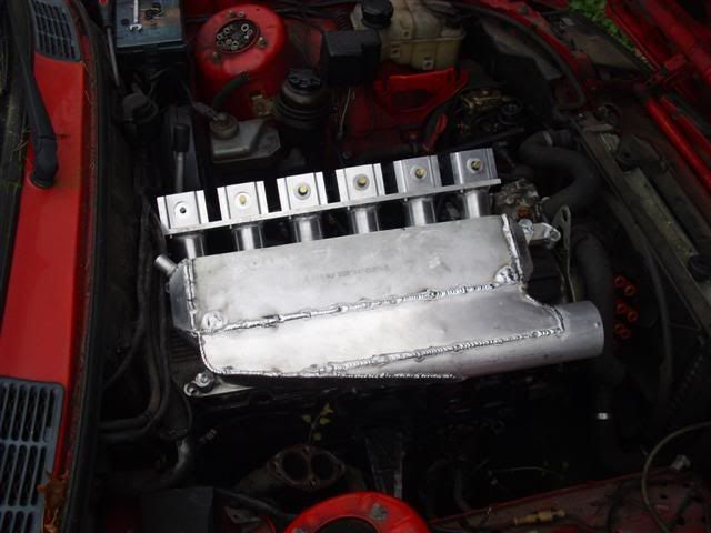
The answer is in a strip of metal which I bent up to see what the under bonnet clearance was actually like....and this is the result:
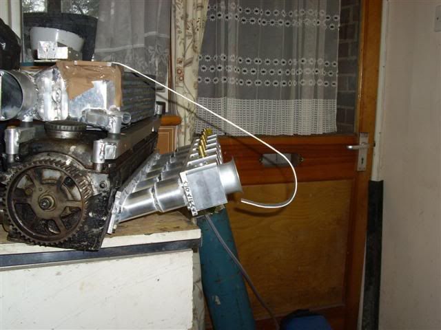
It looks really weird at that angle but with the head on the engine, the long straight bit of the strip is horizontal.
There's about 2" of clearance between the flat and the throttle so the linkage is gonna have to be underslung now, but that shouldn't affect the injector positioning.
So all I'll have now is a shiny sheet of metal and then six little rubber connectors from the air box to the throttles.
It's not gonna be ideal having the air make such a sharp turn, but the flow area is still massive so air can still enter each cylinder from the side too.
So then the head scratching started as to how I might get air from the charge cooler to the throttles.
The answer is in a strip of metal which I bent up to see what the under bonnet clearance was actually like....and this is the result:
It looks really weird at that angle but with the head on the engine, the long straight bit of the strip is horizontal.
There's about 2" of clearance between the flat and the throttle so the linkage is gonna have to be underslung now, but that shouldn't affect the injector positioning.
So all I'll have now is a shiny sheet of metal and then six little rubber connectors from the air box to the throttles.
It's not gonna be ideal having the air make such a sharp turn, but the flow area is still massive so air can still enter each cylinder from the side too.
-
Turbo-Brown
- Boost Junkie
- Posts: 4705
- Joined: Tue Feb 15, 2005 11:00 pm
- Location: Aldershot, Hants
Actually thinking about it, with a plenum as I've shown it there, I should have about the same volume on the inlet side of the throttles as something like one of the M5x engines, just with a vast inlet to that plenum.
-
Speedtouch
- Old Skooler
- Posts: 14099
- Joined: Tue Feb 14, 2006 11:00 pm
- Location: Canterbury
Well, if it doesn't work out, it'll make a nice ornament and talking piece at dinner parties 

///M aurice
ECU Upgrade EPROM Chips, £40 posted within the UK. Note these are not Zone chips.
viewtopic.php?f=6&t=279421
ECU Upgrade EPROM Chips, £40 posted within the UK. Note these are not Zone chips.
viewtopic.php?f=6&t=279421
-
Paynts
- E30 Zone Newbie
- Posts: 135
- Joined: Sun Jan 13, 2008 11:00 pm
doesn't the overall length of inlet tract determine torque characteristics not the shape of the trumpet flange?
I bought some filter socks for my ITBs then my brother who has been running TBs on his big numbers Vauxhall engine showed me this
this info below is from the SBD motor sport site - they are very serious builders of Vauxhall XE engines
make of it what you will. Quite frankly I don't believe I will lose 20 hp running mine but I shall check for myself,
after I've rebuilt my engine i'm going for an RR session and I'll do a with and without
Important Notes
Read below before you waste all the BHP you have spent lots of hard earned money on achieving & throw it away on the intake system.
1. Never use Ram pipe sock filters of any type, you will lose between 20 to 60 BHP.
2. Air filters & air boxes are critical in design & should be tested on a dynamometer to prove losses or gains. An air box can reflect the engines natural pulses & give an improvement at some engine speeds & losses at another. But this can change dramatically due to cam profile, timing exhaust manifold design & shape of air box & an air box that works on one engine spec probably will not work on another e.g. the usual scenario is a gain in torque at low RPM & drop in peak power. Please be warned we have spent Thousands of Pounds on the dynamometer & sometimes got nowhere.AR-AB1 Air box
3. Your engine works by mixing fuel & air, which is ignited to generateheat to force the piston down generating BHP. The hotter the air is when drawn in to the engine, the less dense it will be which means because it is already partially expanded the less it can expand when ignited, this means your engine is generating less power. So the colder the air you can get in, the better BHP you get out, e.g. for every 10 degrees of air temperature you can loss in the region of 5 BHP (we have recorded over a 100 degree in some intake systems in test). So yet again don't waste that hard gained BHP with a hot intake system.
-
Paynts
- E30 Zone Newbie
- Posts: 135
- Joined: Sun Jan 13, 2008 11:00 pm
hi this is a great thread i've become really interested in your project I have a couple of questions whihc made sound stupid but I can't quite grasp whats going on
I'm assuming thats a watercooled charge cooler?
and I'm also assuming that the large pipe in is the inlet from the turbo?
so you are going to fabricate a box with 6 outlets coming off it to go on the other side of the cooler and the outlets willsweep 180 down onto the ITBs?
any reason you didn't go for a Air to air jobby mounted somewhere in the airflow at the front of the car? are you going to use a seperate water system for the chargecooler?
I expect you have already been through all this and I havent read the thread carefully enough
-
Turbo-Brown
- Boost Junkie
- Posts: 4705
- Joined: Tue Feb 15, 2005 11:00 pm
- Location: Aldershot, Hants
The tuned length of the inlet will influence the torque characteristics of the engine, but in the case of this engine boost should be available everywhere in the rev range so pulse tuning of the inlet and exhaust becomes much less important.
The Charge cooler is indeed going to be water cooled with something like a motorbike rad at the front of the car to lose the heat. The large pipe comes from an air divertor assembly which determines whether the boosted air from the small turbo or the large one sees the engine.
The air box will have six outlets but they'll point directly at the throttles and have about a 50mm silicone joiner to connect them to some inlet stubs. The bent up strip of metal shows the outer shape of the air-box-to-be. whilst the inner line of the box will go from the bottom of the charge cooler core to the top of the throttles with a slight radius in it where it bends.
I went for the charge cooler as they have potential to be very efficient and also it gives the charge air about the shortest path to travel into the throttles. The air does have a very large volume to fill, but I believe that having massive flow areas is intrinsic to producing lots of power per psi of boost.
-
Paynts
- E30 Zone Newbie
- Posts: 135
- Joined: Sun Jan 13, 2008 11:00 pm
Alex I'm very impressed you are obviously the man on M20 turbocharging!! I assume this is your second or 3rd turbo project?
I see your point bout the charge cooler rather than Air to Air
As a matter of interest if I finished rebuilding my N/A car ( I'd have to ssell the manifold I have jsut bought) what would it cost me to build a 13 PSI system with my standard bottom end, I would need to make and Air Box for my ITBs but I can tig weld etc
I am currently making 197 BHP @7200 and would like to make circa 240 BHP if pos without having to upgrade everything in the engine
Also I have Weber Alpha management at present what changes would i ahve to make to that?
-
tubby17s
- E30 Zone Newbie
- Posts: 99
- Joined: Wed Mar 28, 2007 11:00 pm
- Location: Australia, sydney
turbo brown.. just walking around my office and thought about your set up for a second.. (dont know why)
Are you going to put like a urethane gasket between your throttle bodies and the head to keep the ITB temps down? Thats what they use on the S14's
just and idea
Josh
Are you going to put like a urethane gasket between your throttle bodies and the head to keep the ITB temps down? Thats what they use on the S14's
just and idea
Josh
-
Turbo-Brown
- Boost Junkie
- Posts: 4705
- Joined: Tue Feb 15, 2005 11:00 pm
- Location: Aldershot, Hants
Crikey, wouldn't say I'm any real kind of authority on turbocharging M20s, just have a reasonable grasp of the basics
I guess the cost depends on how much else you could do yourself. If you can TIG weld, wield a hacksaw and some files then you can make a manifold for a couple of hundred quid out of stainless steel, would get a nice great big turbo like my H1C or one of the more modern Holsets which is another couple of hundred.
You'd need some kind of wastegate and I understand that the generic non-branded ones last just as well as the Tials etc so that's about another £70 or so.
Then there's just the charge / intercooling, piping for the air, an exhaust system, oil feed and drain and the all important engine management.
The engine management would need a MAP sensor (guess it just looks at throttle angle at the moment) you should have a manifold pressure compensation map in the ECU software somewhere.....I hope!
My twin turbo system which I built last time around came to about £4500 and was based on a standard spec early engine (with 9.7:1 compression) which made 270bhp from 7psi.
You would need to look at your compression ratio if you plan on running 13psi, you would make an awful lot more than 240bhp with that too!
I believe I got 270bhp from just 7psi because everything in my system was so overspecced in terms of flow areas with the exhaust being a twin straight through 2", all the inlet piping being twin 2" and it having throttle bodies.
Restrictions are the enemy of power!
Hey Josh, I was just gonna use normal inlet gaskets but you make a good point about isolating the inlet from heat.
Might give Ferriday a shout as I think they can make up isolating gaskets. Either that or get hold of some urethane sheet and make my own
-
Yaninnya
- E30 Zone Regular
- Posts: 512
- Joined: Tue Aug 01, 2006 11:00 pm
- Location: Jersey, CI
Hi Alex,
Is there any reason to keep inlet pipes so long? After shortening it will be a lot easyer to make a good shaped plenum.
Jan
Is there any reason to keep inlet pipes so long? After shortening it will be a lot easyer to make a good shaped plenum.
Jan
-
appletree
- E30 Zone Addict
- Posts: 3482
- Joined: Fri Jan 20, 2006 11:00 pm
- Location: Retford
Hi alex, whilest on holiday i bought a jap car mag and saw these! thought they might be of some use to you!
there suposed to go in the exhaust but i doubt it will make much difference were they go, not sure if there progresive or not but they may be able to be modified to be!
Just a thought
http://www.nemesisuk.com/mm5/merchant.m ... T-CUT-OUTS
there suposed to go in the exhaust but i doubt it will make much difference were they go, not sure if there progresive or not but they may be able to be modified to be!
Just a thought
http://www.nemesisuk.com/mm5/merchant.m ... T-CUT-OUTS
You should never underestimate the predictability of stupidity
M42 Supercharged 285bhp + M3 6speed box
-
Turbo-Brown
- Boost Junkie
- Posts: 4705
- Joined: Tue Feb 15, 2005 11:00 pm
- Location: Aldershot, Hants
Hey Jan, how's it going mate?
Was just thinking today I hadn't seen you on here in a while, you must be psychic!
The length of the runners was dictated by the thermostat housing which gets right in the way of everything!
Could probably have relocated the thermostat housing but thought it'd just be one more thing to go wrong
Hi Matt, did see those thingys in PPC a month or so ago. Not sure they'd be up to living in the exhaust manifold to be honest. Under the car where they get some cooling air and the exhaust has had a chance to cool they're probably fine but right in the thick of the engine bay I reckon would cause them some problems.
The moving around of the valves and flaps is pretty simple in essence, it's telling them where to be for a given set of conditions that's the hard part, although it sounds like Emerald are going to come up trumps for me with the additional PWM maps and possibly some more load sites (fingers crossed!)
-
march109
- Engaged to the E30 Zone
- Posts: 6632
- Joined: Sun Aug 20, 2006 11:00 pm
- Location: Bournemouth
Alex did you see the message I left for you on the other thread? I'm on for the rods.
325i Tech 1 Touring, breaking.
2.5 high comp. M20, 3.64 LSD, Fully undersealed, Spax springs & Bilstein shocks, s/s exhaust, Alpina rep wheels and more.
2.5 high comp. M20, 3.64 LSD, Fully undersealed, Spax springs & Bilstein shocks, s/s exhaust, Alpina rep wheels and more.
-
Yaninnya
- E30 Zone Regular
- Posts: 512
- Joined: Tue Aug 01, 2006 11:00 pm
- Location: Jersey, CI
Not bad, mate!Turbo-Brown wrote:Hey Jan, how's it going mate?
Was just thinking today I hadn't seen you on here in a while, you must be psychic!
The length of the runners was dictated by the thermostat housing which gets right in the way of everything!
Could probably have relocated the thermostat housing but thought it'd just be one more thing to go wrong
I was moving, which wasn't easy with all my stuff (suprise, suprise, tons of strange car parts...
I know that this bloody thermostat housing is PITA (I was replacing it in my E34 not so long time ago). But it will get everything easyer. Maybe M3 thermostat will do (it is hanging on water hoses)?
Jan
-
Turbo-Brown
- Boost Junkie
- Posts: 4705
- Joined: Tue Feb 15, 2005 11:00 pm
- Location: Aldershot, Hants
I did get the message Gareth, been rushed off my feet organising a stag do over the last few days. What a nightmare!
I'm made up in my mind that I'm gonna work around what I've got because if you isolate the plenum into seperate volumes, you get one large collector volume on the outlet side of the cooler core, a transition area into the plenum which is around 25920mm^2, and then the plenum itself which has a volume similar to an M5x plenum.
Got an e-mail from my metal supplier last night to say the ali sheet I've ordered is in the post so I've got everything crossed for it turning up today.
Also been having to chase and chase the supplier of the flywheel! They said two weeks from order to delivery, it's now been about 5 1/2 weeks!