Difference between revisions of "Steering Rack Conversions"
Grrrmachine (talk | contribs) m |
Grrrmachine (talk | contribs) |
||
| Line 1: | Line 1: | ||
| − | + | [[Image:Utf-8BSU1BRzAwNTYuanBn.jpg|thumb|right|450px|The difference between an E30 (front) & E36 rack.]]One of the best features of any E30 is the steering feel; none of this namby-pamby electric power steering, just a good old-fashioned rack-and-pinion setup, so that you can feel the road with your fingertips, via the steering wheel. | |
| − | + | The only downside is the speed. The E30 rack is XXX turns lock-to-lock, which is far too cumbersome for enthusiastic driving. | |
| − | + | But there's good news! You can bolt on a steering rack from newer BMWs with relative ease, giving you faster turns without losing that steering feel. Here's how to do this for '''RHD''' cars. | |
| − | + | =Overview= | |
| − | The | + | Racks from newer BMWs are extremely similar to the original E30 units, and are almost a direct bolt-in replacement. However, you will need to work around a few small technical issues. |
| + | |||
| + | For starters, newer rackers a physically a little bit shorter. This means that you need a pair of small metal spacers so that you can bolt the new rack in exactly the same location as the original rack. The pikey solution is to use a pile of washers, but a sturdier solution is to fabricate your own or buy them ready-made. They need to be 14mm tall, at least 14mm wide, with an internal hole of 10mm diameter. | ||
| + | |||
| + | You also need to customise your steering linkage due to the shorter length of the new rack. We've [[Steering_Rack_Conversions#Steering_Linkage|outlined some options]] to fab your linkage later in this document, but you can also buy a custom linkage from Zone member [http://www.e30zone.net/modules.php?name=Forums&file=profile&mode=viewprofile&u=7093 DanThe]. | ||
| + | |||
| + | Finally, you need to find a solution to the power steering hoses as the holes on the new rack are at a different angle to the originals. Again, you can fab your own if you're ok bending the original pipes, or DanThe can supply you with a brand new set fit for purpose. | ||
| + | |||
| + | To connect your new rack to your wheels, you need inner and outer tie rods on each side. The good news is that you can use standard E30 units, so if your current ones are in good condition then there's no need to buy new parts. However, you CAN'T use complete inner and outer rods from newer BMWs. You can use either....., but not both. | ||
| + | |||
| + | |||
| + | =Parts= | ||
| + | |||
| + | * New Rack | ||
| + | * 14mm rack spacers | ||
| + | * Inner and outer tie rods (complete set of either E30 or E36, but not E46) | ||
| + | * Steering linkage ([[Steering_Rack_Conversions#Steering_Linkage|click here for more info]]) | ||
| + | * New aluminium crush washers (14mm and 16mm) | ||
| + | |||
| + | =Tools= | ||
| + | |||
| + | * Ball-joint splitter | ||
| + | * 13mm, 15mm, 17mm, 19mm and 22mm sockets or spanners | ||
| + | * A hammer and crowbar or suitable drift | ||
| + | |||
| + | |||
| + | ==Which Rack?== | ||
| + | |||
| + | The current choice of racks are: | ||
| + | |||
| + | {| class=wikitable | ||
| + | |- | ||
| + | !Rack | ||
| + | !Part Number | ||
| + | !Turns | ||
| + | (lock to lock) | ||
| + | !Comments | ||
| + | |- | ||
| + | |E30 | ||
| + | | | ||
| + | |4 | ||
| + | |Standard power steering rack for all models | ||
| + | |- | ||
| + | |E36 | ||
| + | | | ||
| + | |3.4 | ||
| + | | | ||
| + | |- | ||
| + | |E36 M3 | ||
| + | | | ||
| + | |3.2 | ||
| + | |Despite the lower lock-to-lock number, the E36 M3 rack isn't any faster; it simply has massive locking plates fitted to it that limit the overall rack movements. Remove these plates, and it's a standard E36 rack. | ||
| + | |- | ||
| + | |E46 | ||
| + | | | ||
| + | | | ||
| + | | | ||
| + | |- | ||
| + | |E46 Clubsport | ||
| + | | | ||
| + | | | ||
| + | |The most popular choice. Fitted to a range of E46s - look for the purple tag. | ||
| + | |- | ||
| + | |Z3 | ||
| + | | | ||
| + | |2.7 | ||
| + | |The fastest rack, and no need for a custom steering linkage, makes this the perfect rack. But most are now well over 20 years old, so finding a good one is increasingly difficult. | ||
| + | |} | ||
| + | |||
| + | =Procedure= | ||
| + | |||
| + | ==Removal== | ||
| + | |||
| + | First off, get the car up in the air. A post-lift would be great, but most of us will have to manage with a pair of jack stands under the chassis rails. DO NOT DO THIS with just a jack. You will die. | ||
| + | |||
| + | With the front raised up, remove both front wheels and place them under the sills of the car, for added safety. | ||
| + | |||
| + | Now we can start removing the existing components. | ||
| + | |||
| + | First thing to do is separate the tie rod ends from the suspension struts. For better access, turn the steering to each side. A 17mm thread lock nut holds the tie rod end to the strut so get this undone and then drop the tie rod from the strut. These two simple tasks can often be fraught with hassle due to parts being seized. If the balljoint spins while undoing the nut, place your jack under the ball joint and take the weight of the strut on the jack and try again to undo the nut. Failing that, another trick is to use heat such as a blowtorch, which can also work for removing the tie rod from the strut. A hammer and block of wood is also a commonly used way of separating the parts. | ||
| + | |||
| + | [[Image:SteeringRack004.jpg|center|300px]] | ||
| + | |||
| + | Depending on their condition, you may want to salvage the inner and outer tie rods. If you do, then you need to remove them while the rack is still bolted to car; they're a real pain to remove otherwise. | ||
| + | |||
| + | It is '''critical''' that you do not touch the adjustment nut between the inner and outer tie rod. If you do, you will have to go through the whole process of having your steering geometry (tracking) adjust once the installation is complete. Leave them completely alone for now. | ||
| + | |||
| + | Instead, prise off the metal ricg around the rubber boot at the steering rack end. Peel back the rubber to expose the nut on the inner tie rod, as well as the locking ring plate. The locking plate is a thin metal washer that has been bent over the tie rod nut to hold it in place. You need to bend the locking plate away from the nut, then get your spanner on the nut and give it a sharp twist. With luck, it'll start turning, allowing you to twist the entire tie rod assembly off the rack for re-use later. | ||
| + | |||
| + | The next thing to remove is the linkage that attaches the steering rack to the column. This is secured with a 13mm nut and bolt at either end which need removing. The UJ should then slide down the splines towards the rack off the column and can then be pulled off the rack. These are often seized but some penetrating fluid and a couple of knocks with a small hammer should have it moving; there is no need to attack it with a chisel or anything similarly brutal. | ||
| + | |||
| + | Now we need to disconnect the pipework. If you have access due to a post-lift, then undo the banjo bolts (19 & 22mm) on the rack itself and drain the fluid there. If you don't have access, it's worth undoing the two pipes on the steering pump first. Because these are much easier to access, you can drain all the steering fluid out of the reservoir with relative ease, without it dripping all over your face while you work underneath the rack. | ||
| + | |||
| + | [[Image:SteeringRack003.jpg|center|300px]] | ||
| + | |||
| + | Now all that is left is removing the rack from its mounting on the crossmember. The rack is held to the crossmember by two 15mm nuts and bolts; simply undo and remove these. Then to remove the rack the bottom tabs need to be bent out of the way which will provide the room to simply drop the steering rack off the car. | ||
| + | |||
| + | [[Image:SteeringRack002.jpg|center|300px]] | ||
| + | |||
| + | ==Steering Linkage== | ||
| + | |||
| + | There are a number of options when it comes to linkages. The choice depends on what [[Engines|engine]] and [[Exhaust#Manifold|exhaust manifold]] you currently have fitted, as certain combinations lead to the linkage fouling on the exhaust. | ||
| − | + | ===E36 hybrid=== | |
| − | + | This design combines the upper universal joint (UJ) from the E30 joint, and the lower UJ from an E36 joint. You also need to make an aluminium or steel spacer to join them together. The standard E30 joint is approx 275mm long. This needs to be shortened by 25mm to 250mm long. | |
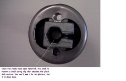
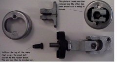
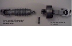
The E36 joint is made in 2 parts. The top half consists of the top UJ and a convoluted portion. This is connected to the lower UJ (and rubber flex joint) by a simple pinch bolt. Remove the bolt and discard the top portion. You now have the lower UJ with the rubber flex joint. You need to drill out the 2 large rivets that hold the pinch bolt section to the flex joint. If you look down the centre of the pinch bolt section, you will also see a small securing clip. Remove this with a small screwdriver. You should now have the lower UJ with the flex joint and 2 empty holes. | The E36 joint is made in 2 parts. The top half consists of the top UJ and a convoluted portion. This is connected to the lower UJ (and rubber flex joint) by a simple pinch bolt. Remove the bolt and discard the top portion. You now have the lower UJ with the rubber flex joint. You need to drill out the 2 large rivets that hold the pinch bolt section to the flex joint. If you look down the centre of the pinch bolt section, you will also see a small securing clip. Remove this with a small screwdriver. You should now have the lower UJ with the flex joint and 2 empty holes. | ||
| Line 21: | Line 122: | ||
Now, back to the hole in the disc. This is for the centering bush (similar to the nylon one on the E30 joint). If you look at the pinch bolt section you removed earlier, you should see a bronze bush in the centre. This is retained by some deformations (stakes ?) in the housing. With some careful drill work, the bush can be removed. It also helps if you cut through the side of the housing and open it up with a chisel. You need to make the hole in the centre of your new metal disc the same as the O/D of the bush. It needs to be a snug fit, and can be retained with some bearing securing solution (Loctite etc). | Now, back to the hole in the disc. This is for the centering bush (similar to the nylon one on the E30 joint). If you look at the pinch bolt section you removed earlier, you should see a bronze bush in the centre. This is retained by some deformations (stakes ?) in the housing. With some careful drill work, the bush can be removed. It also helps if you cut through the side of the housing and open it up with a chisel. You need to make the hole in the centre of your new metal disc the same as the O/D of the bush. It needs to be a snug fit, and can be retained with some bearing securing solution (Loctite etc). | ||
| − | + | <gallery mode="nolines" perrow="3" widths=250px heights=161px> | |
| + | Image:rack_001.jpg | ||
| + | Image:rack_002.jpg | ||
| + | Image:rack_003.jpg | ||
| + | Image:rack_004.jpg | ||
| + | Image:rack_005.jpg | ||
| + | Image:rack_006.jpg | ||
| + | Image:rack_007.jpg | ||
| + | Image:rack_008.jpg | ||
| + | Image:rack_009.jpg | ||
| + | Image:rack_010.jpg | ||
| + | Image:rack_011.jpg | ||
| + | Image:rack_012.jpg | ||
| + | Image:rack_013.jpg | ||
| + | Image:rack_014.jpg | ||
| + | Image:rack_015.jpg | ||
| + | Image:rack_016.jpg | ||
| + | Image:rack_017.jpg | ||
| + | Image:rack_018.jpg | ||
| + | Image:rack_019.jpg | ||
| + | Image:rack_020.jpg | ||
| + | </gallery> | ||
| − | [[Image: | + | ===Ready-made=== |
| + | [[Image:E36 steering pipes and linkage.jpg|thumb|right|DanThe's steering linkage]] | ||
| + | Forum user [http://www.e30zone.net/modules.php?name=Forums&file=profile&mode=viewprofile&u=7093 DanThe] supplies a custom knuckle that's a simple bolt-in replacement for the existing system. These knuckles are very similar to the [[Steering_Rack_Conversions#E36_Hybrid|E36 hybrid]], but use an E34 universal joint instead. | ||
| − | + | ===Guibo Delete=== | |
| − | + | Because the original linkage needs to be shortened by 25mm, a simple solution is to remove the rubber guibo and bolt the two solid ends together. | |
| − | + | Undo the bolts to remove the guibo and bolt the universal joints together. It's recommended to put two washers between the joints (one washer per bolt) as the flat surfaces aren't completely parallel. | |
| + | You may find the bolt holes are the same size in each UJ, but some do have different sized holes (either 8mm 10mm). If desired, you can drill the smaller holes to match the larger ones on the linkage. | ||
| − | [[ | + | The only issue is that it doesn't create anymore linkage to manifold clearance (which may be a problem with a 6 branch or [[Engine_Swap_-_M5x|M5x conversions]]), as opposed to the [[Steering_Rack_Conversions#Ready-made|ready-made]] linkage. |
| − | + | ===Opel Corsa C=== | |
| − | [[ | + | ''Main article: [[Corsa_Steering_Linkage|Opel Corsa C Steering linkage]]'' |
| − | [[ | + | One ingenious solution is to use parts from a similar-period Opel/Vauxhall Corsa. For more information, check out how to make the [[Corsa_Steering_Linkage|Opel Corsa C Steering knuckle]] |
| − | + | ==Fitting== | |
| − | + | Choose the appropriate steering linkage from the above options, and fit it to your steering shaft. Once it's on and secure, set the steering wheel straight and then lock the column by removing your ignition key. | |
| − | + | Prepare the new rack. If you've bought new steel pipes, fit them to the rack now. | |
| − | + | Straighten the rack. It needs to be set to point straight ahead, which means turning it so that the rack is of equal length on both sides. Use a ruler, and turn the input nut with a 13mm spanner until both sides are the same length: | |
| − | [[Image: | + | [[Image:SteeringRack001.jpg|center|300px]] |
| + | [[Image:DSC00446.JPG|thumb|right|140px|Rack mounted in the NON-PAS position]] | ||
| + | You're now ready to offer up the rack. Slide it up into the space under the subframe, and get the steering linkage onto the rack's input splines. It probably won't slide on smoothly, but some wiggling will at least make them mesh by a few millimeters, which is a good start. You can bend the lower subframe tabs back now to stop the rack dropping out of the car. | ||
| − | + | We now need to get things aligned, which is hard if the steering linkage isn't completely on because you can't line up the rack bolt-holes with the holes on the subframe. A handy tip is to use two thick screwdrivers as levers so that you can prise the rack closer to its intended location, then clout the steering linkage downwards from above (using a long crowbar or drift). Eventually, you'll get the linkage solidly onto the rack, and you can fit and tighten the linkage bolt to secure it. | |
| − | [[Image: | + | With the linkage secure, we can bolt up the rack. There are two holes per side of the subframe; front for non-PAS racks, and rear for PAS racks. The holes you use will depend on which linkage you're using, but aim to fit your new rack into the rear holes - it results in a better driving feel. Wiggle the rack until you can slide a bolt up from underneath, then place your spacer (or washers) between the top of the rack and the top subframe tab. Put the nut on top, and tighten up. |
| + | |||
| + | [[Image:E36_rack_spacers.jpg|thumb|center|300px|Spacers placed between top of rack and subframe]] | ||
| + | |||
| + | Now is a good time to get your pipes connected. If you've ordered cusom pipes, you'll need to fit one hose to your PAS reservoir and the other to your PAS pump. It's easier to fit the PAS reservoir hose first, then | ||
| + | |||
| + | |||
| + | |||
| + | |||
| + | |||
| + | |||
| + | |||
| + | |||
| + | The E36 rod ends bolt straight to the E30 steering arms, so no problem there. You could probably use the E36 power steering pipes with a bit of modification (bending), or have custom pipes made. I chose the latter solution. | ||
| − | |||
| − | [[Image: | + | [[Image:318is undertray mod.jpg|thumb|right|140px|318iS plastic under-tray modified for rack fitment.]] |
| − | |||
| − | |||
| − | |||
[[Category: Technical]] | [[Category: Technical]] | ||
[[Category: Steering]] | [[Category: Steering]] | ||
[[Category: Upgrades]] | [[Category: Upgrades]] | ||
Revision as of 13:49, 27 April 2014
One of the best features of any E30 is the steering feel; none of this namby-pamby electric power steering, just a good old-fashioned rack-and-pinion setup, so that you can feel the road with your fingertips, via the steering wheel.
The only downside is the speed. The E30 rack is XXX turns lock-to-lock, which is far too cumbersome for enthusiastic driving.
But there's good news! You can bolt on a steering rack from newer BMWs with relative ease, giving you faster turns without losing that steering feel. Here's how to do this for RHD cars.
Contents
Overview
Racks from newer BMWs are extremely similar to the original E30 units, and are almost a direct bolt-in replacement. However, you will need to work around a few small technical issues.
For starters, newer rackers a physically a little bit shorter. This means that you need a pair of small metal spacers so that you can bolt the new rack in exactly the same location as the original rack. The pikey solution is to use a pile of washers, but a sturdier solution is to fabricate your own or buy them ready-made. They need to be 14mm tall, at least 14mm wide, with an internal hole of 10mm diameter.
You also need to customise your steering linkage due to the shorter length of the new rack. We've outlined some options to fab your linkage later in this document, but you can also buy a custom linkage from Zone member DanThe.
Finally, you need to find a solution to the power steering hoses as the holes on the new rack are at a different angle to the originals. Again, you can fab your own if you're ok bending the original pipes, or DanThe can supply you with a brand new set fit for purpose.
To connect your new rack to your wheels, you need inner and outer tie rods on each side. The good news is that you can use standard E30 units, so if your current ones are in good condition then there's no need to buy new parts. However, you CAN'T use complete inner and outer rods from newer BMWs. You can use either....., but not both.
Parts
- New Rack
- 14mm rack spacers
- Inner and outer tie rods (complete set of either E30 or E36, but not E46)
- Steering linkage (click here for more info)
- New aluminium crush washers (14mm and 16mm)
Tools
- Ball-joint splitter
- 13mm, 15mm, 17mm, 19mm and 22mm sockets or spanners
- A hammer and crowbar or suitable drift
Which Rack?
The current choice of racks are:
| Rack | Part Number | Turns
(lock to lock) |
Comments |
|---|---|---|---|
| E30 | 4 | Standard power steering rack for all models | |
| E36 | 3.4 | ||
| E36 M3 | 3.2 | Despite the lower lock-to-lock number, the E36 M3 rack isn't any faster; it simply has massive locking plates fitted to it that limit the overall rack movements. Remove these plates, and it's a standard E36 rack. | |
| E46 | |||
| E46 Clubsport | The most popular choice. Fitted to a range of E46s - look for the purple tag. | ||
| Z3 | 2.7 | The fastest rack, and no need for a custom steering linkage, makes this the perfect rack. But most are now well over 20 years old, so finding a good one is increasingly difficult. |
Procedure
Removal
First off, get the car up in the air. A post-lift would be great, but most of us will have to manage with a pair of jack stands under the chassis rails. DO NOT DO THIS with just a jack. You will die.
With the front raised up, remove both front wheels and place them under the sills of the car, for added safety.
Now we can start removing the existing components.
First thing to do is separate the tie rod ends from the suspension struts. For better access, turn the steering to each side. A 17mm thread lock nut holds the tie rod end to the strut so get this undone and then drop the tie rod from the strut. These two simple tasks can often be fraught with hassle due to parts being seized. If the balljoint spins while undoing the nut, place your jack under the ball joint and take the weight of the strut on the jack and try again to undo the nut. Failing that, another trick is to use heat such as a blowtorch, which can also work for removing the tie rod from the strut. A hammer and block of wood is also a commonly used way of separating the parts.
Depending on their condition, you may want to salvage the inner and outer tie rods. If you do, then you need to remove them while the rack is still bolted to car; they're a real pain to remove otherwise.
It is critical that you do not touch the adjustment nut between the inner and outer tie rod. If you do, you will have to go through the whole process of having your steering geometry (tracking) adjust once the installation is complete. Leave them completely alone for now.
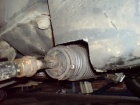
Instead, prise off the metal ricg around the rubber boot at the steering rack end. Peel back the rubber to expose the nut on the inner tie rod, as well as the locking ring plate. The locking plate is a thin metal washer that has been bent over the tie rod nut to hold it in place. You need to bend the locking plate away from the nut, then get your spanner on the nut and give it a sharp twist. With luck, it'll start turning, allowing you to twist the entire tie rod assembly off the rack for re-use later.
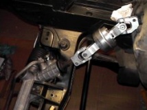
The next thing to remove is the linkage that attaches the steering rack to the column. This is secured with a 13mm nut and bolt at either end which need removing. The UJ should then slide down the splines towards the rack off the column and can then be pulled off the rack. These are often seized but some penetrating fluid and a couple of knocks with a small hammer should have it moving; there is no need to attack it with a chisel or anything similarly brutal.
Now we need to disconnect the pipework. If you have access due to a post-lift, then undo the banjo bolts (19 & 22mm) on the rack itself and drain the fluid there. If you don't have access, it's worth undoing the two pipes on the steering pump first. Because these are much easier to access, you can drain all the steering fluid out of the reservoir with relative ease, without it dripping all over your face while you work underneath the rack.
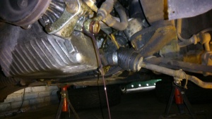
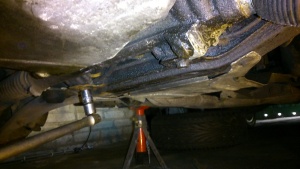
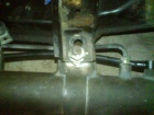
Now all that is left is removing the rack from its mounting on the crossmember. The rack is held to the crossmember by two 15mm nuts and bolts; simply undo and remove these. Then to remove the rack the bottom tabs need to be bent out of the way which will provide the room to simply drop the steering rack off the car.
Steering Linkage
There are a number of options when it comes to linkages. The choice depends on what engine and exhaust manifold you currently have fitted, as certain combinations lead to the linkage fouling on the exhaust.
E36 hybrid
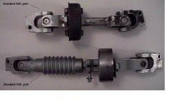
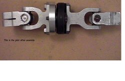
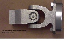
This design combines the upper universal joint (UJ) from the E30 joint, and the lower UJ from an E36 joint. You also need to make an aluminium or steel spacer to join them together. The standard E30 joint is approx 275mm long. This needs to be shortened by 25mm to 250mm long.
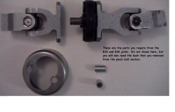
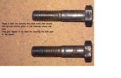
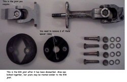
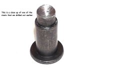
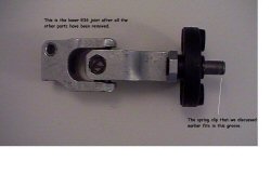
The E36 joint is made in 2 parts. The top half consists of the top UJ and a convoluted portion. This is connected to the lower UJ (and rubber flex joint) by a simple pinch bolt. Remove the bolt and discard the top portion. You now have the lower UJ with the rubber flex joint. You need to drill out the 2 large rivets that hold the pinch bolt section to the flex joint. If you look down the centre of the pinch bolt section, you will also see a small securing clip. Remove this with a small screwdriver. You should now have the lower UJ with the flex joint and 2 empty holes.
On the E30 joint, you need to perform a similar operation. You want just the upper UJ. You may just need to unbolt the existing flex joint if it has previously been replaced. If it is still a 'Virgin', you will need to drill the rivets out.
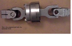
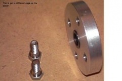
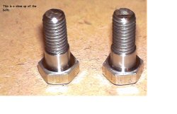
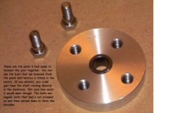
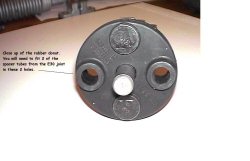
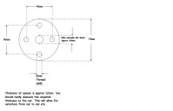
If you offer up the upper E30 joint to the flex joint on the E36 UJ, you will notice that the holes do not align very well. The bolt spacing on the E36 joint is 45mm, and on the E30 it is 50mm. You will also find that the overall length is only 240mm (10mm short). These 2 problems are easily overcome by making a metal (Aluminium or Steel) disc approx 10mm thick with a hole in the centre (I will come back to this hole). You need to drill 2 holes 45mm apart and another 2 holes 50mm apart. These sets of holes need to be offset by 90 degrees. This will allow you to bolt the E30 and E36 UJ's together. The overall length should now be correct. You will need to use 2 of the metal spacer tubes from the E30 flex joint and fit them in the E36 flex joint. You will see what I mean when it is in front of you. The actual thickness of the spacer should be measured on the car to allow for different tolerances between cars and parts etc. 10mm is a rough guide.
Now, back to the hole in the disc. This is for the centering bush (similar to the nylon one on the E30 joint). If you look at the pinch bolt section you removed earlier, you should see a bronze bush in the centre. This is retained by some deformations (stakes ?) in the housing. With some careful drill work, the bush can be removed. It also helps if you cut through the side of the housing and open it up with a chisel. You need to make the hole in the centre of your new metal disc the same as the O/D of the bush. It needs to be a snug fit, and can be retained with some bearing securing solution (Loctite etc).
Ready-made
Forum user DanThe supplies a custom knuckle that's a simple bolt-in replacement for the existing system. These knuckles are very similar to the E36 hybrid, but use an E34 universal joint instead.
Guibo Delete
Because the original linkage needs to be shortened by 25mm, a simple solution is to remove the rubber guibo and bolt the two solid ends together.
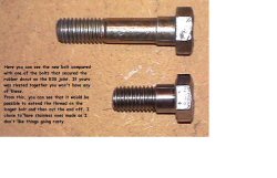
Undo the bolts to remove the guibo and bolt the universal joints together. It's recommended to put two washers between the joints (one washer per bolt) as the flat surfaces aren't completely parallel. You may find the bolt holes are the same size in each UJ, but some do have different sized holes (either 8mm 10mm). If desired, you can drill the smaller holes to match the larger ones on the linkage.
The only issue is that it doesn't create anymore linkage to manifold clearance (which may be a problem with a 6 branch or M5x conversions), as opposed to the ready-made linkage.
Opel Corsa C
Main article: Opel Corsa C Steering linkage
One ingenious solution is to use parts from a similar-period Opel/Vauxhall Corsa. For more information, check out how to make the Opel Corsa C Steering knuckle
Fitting
Choose the appropriate steering linkage from the above options, and fit it to your steering shaft. Once it's on and secure, set the steering wheel straight and then lock the column by removing your ignition key.
Prepare the new rack. If you've bought new steel pipes, fit them to the rack now.
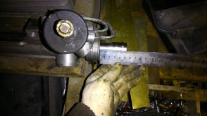
Straighten the rack. It needs to be set to point straight ahead, which means turning it so that the rack is of equal length on both sides. Use a ruler, and turn the input nut with a 13mm spanner until both sides are the same length:
You're now ready to offer up the rack. Slide it up into the space under the subframe, and get the steering linkage onto the rack's input splines. It probably won't slide on smoothly, but some wiggling will at least make them mesh by a few millimeters, which is a good start. You can bend the lower subframe tabs back now to stop the rack dropping out of the car.
We now need to get things aligned, which is hard if the steering linkage isn't completely on because you can't line up the rack bolt-holes with the holes on the subframe. A handy tip is to use two thick screwdrivers as levers so that you can prise the rack closer to its intended location, then clout the steering linkage downwards from above (using a long crowbar or drift). Eventually, you'll get the linkage solidly onto the rack, and you can fit and tighten the linkage bolt to secure it.
With the linkage secure, we can bolt up the rack. There are two holes per side of the subframe; front for non-PAS racks, and rear for PAS racks. The holes you use will depend on which linkage you're using, but aim to fit your new rack into the rear holes - it results in a better driving feel. Wiggle the rack until you can slide a bolt up from underneath, then place your spacer (or washers) between the top of the rack and the top subframe tab. Put the nut on top, and tighten up.
Now is a good time to get your pipes connected. If you've ordered cusom pipes, you'll need to fit one hose to your PAS reservoir and the other to your PAS pump. It's easier to fit the PAS reservoir hose first, then
The E36 rod ends bolt straight to the E30 steering arms, so no problem there. You could probably use the E36 power steering pipes with a bit of modification (bending), or have custom pipes made. I chose the latter solution.


