E30 M3 minor rust repair (few finished pic's)

Doing a minor build / restoration or an epic one, post it here

Moderator: martauto

User avatar
Jozi
E30 Zone Addict
E30 Zone Addict
Posts: 3076
Joined: Thu Nov 22, 2007 11:00 pm
Location: Dublin, Ireland

Tue Dec 07, 2010 10:43 pm

I think he's waiting on the block to come back from the states.

EDIT:
xworks @ E30owners.comt wrote: All progress has ground to a complete halt as we wait for the cylinder head
to return from across the water after having machine work done.
Was supposed to have been back 3 weeks ago.
Last edited by Jozi on Tue Dec 07, 2010 10:45 pm, edited 2 times in total.
aaronsmart
E30 Zone Regular
E30 Zone Regular
Posts: 822
Joined: Fri Dec 18, 2009 11:00 pm
Location: Bournemouth

Tue Dec 07, 2010 10:43 pm

:group:

Me to
Image
x-works
E30 Zone Regular
E30 Zone Regular
Posts: 332
Joined: Thu Mar 10, 2005 11:00 pm
Location: Ireland
Contact:

Tue Dec 07, 2010 10:57 pm

ho, ho, ho, ye funny shower of fu*kers :D

Contrary to popular belief I'm not actually in extensive negotiations
with the IMF for a bailout fund to finish the project. (not far off it mind you.)
The engine build is still ongoing, albeit at a snails pace. The sub zero temp's
out in the garage in the evenings aren't helping either, wearing 15 layers of
clothing might keep you warm but it also leaves you with the agility of the
fuckin Stay Puft Man from Ghostbusters....

Image

All going according to plan the final measurements needed to order the custom
pistons should be collected in the next week or two.
And then there'll be a 4 to 6 week wait while the pistons are made and
shipped out to me (JE pistons across the pond).
When they finally arrive we can start the assembly.

Have a lot of the pre assembly work done.....

Image

but, I've decided not to post anything up till the engine is actually bolted together.
That way, hopefully, the thread shall read in order of when each
engine job should be done as the build comes together, not arse about
tit if I started slapping things up now.

It's taken two and a half years to get to this point, so,
in all honesty, theres not much point rushing now.........
:wink:
e21Jason
E30 Zone Addict
E30 Zone Addict
Posts: 2040
Joined: Tue Jan 11, 2005 11:00 pm
Location: Dubai, UAE

Tue Dec 07, 2010 11:03 pm

I see a few tasty bits there, a distributor blanking plate and trigger wheel from Lee and a carbon air box what ECU are you running

Jason
BMW e21 track car supercharged s14 cage and fabrication by www.chizfab.com
Z3M Coupe for sale
69 Alfa spyder
x-works
E30 Zone Regular
E30 Zone Regular
Posts: 332
Joined: Thu Mar 10, 2005 11:00 pm
Location: Ireland
Contact:

Tue Dec 07, 2010 11:10 pm

Planning to use a DTA S40.
snakebrain
E30 Zone Addict
E30 Zone Addict
Posts: 3685
Joined: Tue Aug 11, 2009 11:00 pm

Tue Dec 14, 2010 4:03 am

e30mazm3 wrote:Credit crunch has properly got the poor man. The amount spent so far must be ridiculous!
I don't think this project's about money....
Gwynleym10
E30 Zone Addict
E30 Zone Addict
Posts: 3650
Joined: Sun Jan 09, 2005 11:00 pm
Location: London/Cymru
Contact:

Wed Jan 12, 2011 1:59 pm

I have finally read all this thread - took me three nights! Really really impressive work.

I just wish as a society as a whole people could appreciated this kind of thing for its real worth (and allow public funding or something for it....!)

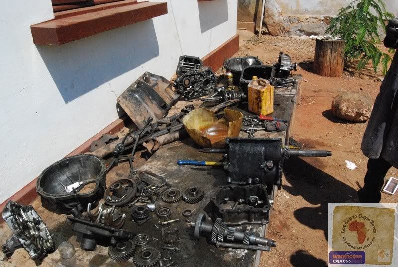
Love the gearbox tear down nice to see how it is supposed to be done! not like my landcruiser one in Northern Mozambique as the picture below shows...

Image

Yes I still dream about gearboxes...
Image
Dual wheel carriers -------195litre Fuel Tank
London 2 Cape Town
www.Overlandinthesun.com
dn808e2
E30 Zone Regular
E30 Zone Regular
Posts: 499
Joined: Sat Mar 11, 2006 11:00 pm
Location: Kings lynn, Norfolk.

Sat Feb 05, 2011 12:26 am

Sorry if i missed the part where the engine power was mentioned , :D , hope the your BM will be on the road this summer.
User avatar
Royalratch
E30 Zone Addict
E30 Zone Addict
Posts: 4921
Joined: Sat Oct 21, 2006 11:00 pm
Location: London

Mon Feb 14, 2011 3:21 pm

What's the leanest dude? How come you went to the USA for engine work?
x-works
E30 Zone Regular
E30 Zone Regular
Posts: 332
Joined: Thu Mar 10, 2005 11:00 pm
Location: Ireland
Contact:

Mon Feb 14, 2011 4:13 pm

Just waiting on pistons and cam followers to arrive and then I can start
the dummy build and then the final engine build. All machine work was either
done locally or in the case of the cylinder head, England. The pistons that I'm waiting
on are coming from California (JE pistons). Took me a little while to get my head around
specifying the dimensions for the pistons. Here's the thread where I got most of the
information for them......
http://www.s14.net/forums/showthread.php?t=49450
User avatar
Royalratch
E30 Zone Addict
E30 Zone Addict
Posts: 4921
Joined: Sat Oct 21, 2006 11:00 pm
Location: London

Thu Feb 24, 2011 6:01 pm

Custom pistons for custom power eh. winkeye
kman82
E30 Zone Regular
E30 Zone Regular
Posts: 967
Joined: Mon Sep 22, 2008 11:00 pm
Location: Oxford

Fri Apr 15, 2011 6:44 pm

hope you havn't forgetten about us x-works. I'm dying to see how the engine rebuild goes
x-works
E30 Zone Regular
E30 Zone Regular
Posts: 332
Joined: Thu Mar 10, 2005 11:00 pm
Location: Ireland
Contact:

Fri Apr 15, 2011 7:11 pm

No, no, I haven't. Just finished uploading the last of 400 pic's to the server over
the last few nights and hope to get some time over the next week to scribble some
tripe down to accompany them. Trying to make the next episode a little more technical
then the last few, it'll still be pure bullsh*t, but I'm going to concentrate on using bigger
words. winkeye
Gortour
E30 Zone Team Member
Posts: 9025
Joined: Sat Sep 23, 2006 11:00 pm
Location: Poole, Dorset

Fri Apr 15, 2011 7:13 pm

Looking forward to it. Hope the tripe doesn't give you wind like it does dogs... :lol:
Currently slumming it in an E46 Touring
x-works
E30 Zone Regular
E30 Zone Regular
Posts: 332
Joined: Thu Mar 10, 2005 11:00 pm
Location: Ireland
Contact:

Sun Apr 17, 2011 10:51 pm

Well, how are ya? Good? Excellent! It's been a while since we last talked
and I've a pile of shite here to bore you with. Believe it or not I still haven't
managed to bolt together this bloody engine. However, I have just finished
all the prep work and need to empty all this crap out of the camera before
it bursts at the seams. So...... how the hell have I managed to spend the last
six months at this and still not built a simple engine? Well, it would appear I
possess a rare talent, the ability to drag out each and every task to its absolute
maximum length, however, in my defence, as this story unfolds you'll see
this river hasn't run smoothly.....

If you can remember all the way back to the time when Jesus was a young boy and I started
the bodywork on this restoration, you may remember that the preparation phase of the
bodywork took a lot longer than the actual spraying part, well, engine building is much
the same. While you could probably assemble an engine in a fairly short space of time
if you have all the parts in front of you, checking, measuring, cleaning and preping the parts
beforehand takes a great deal longer. But, just like the bodywork, if you don't spend
the time on the prep work the end result will almost always suffer.

One small point before we go any further, I'm not going to go into the minute details of
engine building in this thread for two simple reasons.....
a) theres a wealth of knowledge and fantasticly detailed build threads out there of how
to choose the right cams, pistons, valves etc. for your specific engine build and I'm far too dumb
to try and add to that knowledge.
b) what does seem to be scarce out there is some explanations of the simpler
stuff for people who may never have built an engine before,
like what to check to see if parts like the block, crankshafts, conrods etc are fit
to be reused again. If you've built your share of engines in the past then it's unlikely
you'll pick up anything useful here, however, if you've never built an engine before
then hopefully........ you'll fail to realise that most of whats to follow is,
as usual,
probably wrong!

First up, a quick word on measuring. When your looking up spec's for wear tolerances
or shopping for measuring tools then you'll most likley come across the two different
units of measurement common in the trade. Metric and Imperial.
Things usually tend to be a little less confusing if you choose one type and stick to it
for all your measuring. In this regard the various overhaul manuals from BMW for our
cars are well laid out and almost always give all important measurements and
tolerances in both millimetres and thousands of an inch.

Below you can see a little diagram of how each of the units of measure relate to each other.
The large blue circle on the left represents 1 thousandth of an Inch (1 thou) or 0.001" as you'll
usually see it written. To try and give some perspective to this measurement, the average human
hair is 2 thou thick. For most of the tighter tolerances in this engine build we'll be measuring
down to ten thousandths of an inch, 0.0001", thats 20 times smaller than that hair you just plucked
and it's represented below by the smaller of the two blue circles.........


Image
Last edited by x-works on Sun Apr 17, 2011 11:03 pm, edited 1 time in total.
x-works
E30 Zone Regular
E30 Zone Regular
Posts: 332
Joined: Thu Mar 10, 2005 11:00 pm
Location: Ireland
Contact:

Sun Apr 17, 2011 11:03 pm

The other two red circles above represent the similar metric sizes, a hundredth
of a mm and a thousandth of a millimetre.
In the following waffle I tend to favour Imperial measurements using Thou and
Ten Thousandths of an inch, however, it would appear I also switch over to
millimetres at times as well, because, just between you and me, my brain is
mush.
The reason I'm telling you this, is if your going to be using any of this info to
check your own engine parts (very brave) then you need to be careful of
what units are being used.
The following link is to an online converter to change between thou and
mm and can be quite handy to have....
http://www.alcula.com/conversion/length ... illimeter/
One other final link before we get started and thats to BMW's
Tolerance and Torque manual, all the data you'll need for figuring out
working clearances and so on can be found here.....
http://www.bmwtechinfo.com/repair/main/941en/index.htm
Click "Contents" then "engine" and then choose your weapon of choice.

Right, all that shite done with, it's on to the actual engine bits, starting with
the block. After the engine was stripped, the block was "hot tanked" and
steam cleaned in every orifice to remove all the gunk that had built up over
the previous 20 odd years........

Image

next up was to check the flatness of the deck face. This is the surface the
headgasket has to seal against when it's sandwiched between the block and the
cylinderhead, and as such it needs to be perfectly flat and smooth.
To check this we use an engineers straight edge which is basically a very straight
piece of tool steel. This is placed across the deck and you check to see if a 1 thou
feeler blade will fit in anywhere underneath indicating that the surface isn't quite flat enough.......

Image

The block needs to be checked in all the following directions......

Image

As you can see above my deck face looks suspiciously clean and flat and
thats because when disassembled at the very start of this restoration the
surface was found to be a bit uneven and as a result I had the local machine shop
surface grind the deck 0.002" to flatten it out. Unfortunately this was so long ago
that cameras weren't invented and I don't have any before pictures to show you.
Last edited by x-works on Sun Apr 17, 2011 11:07 pm, edited 1 time in total.
x-works
E30 Zone Regular
E30 Zone Regular
Posts: 332
Joined: Thu Mar 10, 2005 11:00 pm
Location: Ireland
Contact:

Sun Apr 17, 2011 11:06 pm

Another job that was carried out at the machine shop was the block was "crack tested".
Basically this involves the use of a strong electro magnet, some coloured metal dust and an
ultraviolet light. This process should show up any stress cracks in the block and
stop you spending any more money on preping it because it's most likely just
been relegated to boat anchor status. If your curious to see how the process works
look up "Magnaflux" on youtube.

Next up is the cylinders, the holes in which the pistons are to travel in. As could probably be
expected the bores on my block were fairly well worn from over a hundred
and seventy thousand miles of one careful owner and five wanabe Arton Senna's.
Usually on a high mileage rebuild like this the block will need
to be "re-bored", the reason being the bores are so worn that to refit the
same size pistons again would leave them wobbling around like a stick in a
welly boot. There are oversize piston sizes available from the main dealer to deal with
this situation
standard size is = 93.355mm/3.675"
first oversize is = 93.555mm/3.683"
second oversize is = 93.755mm/3.691"

Your job is to decide which piston will you need. Common logic dictates that you should only
go as large as you need and therefore try and leave one more oversize piston to "bore to"
down the line should the block need another rebore at a future rebuild. However, you may not
have the luxury of this choice if your cylinders are badly worn. A good machine shop should be able
to advise which size the block needs to be bored to, to remove all traces of wear and return the
cylinder to a factory fresh finish ready for new pistons. As mentioned previously, I had my block at the
machine shop a long time ago (in an effort to speed up the rebuild, seems funny now looking back)
and the resulting wear meant that I had to get my block bored out quite heavily to return it to a usable state.
However, there is one slight difference with my specific build, and that is I am intending to
use custom pistons. These would be made to my own stated sizes and so all I had to ask of
the machine shop was to rebore all 4 cylinders to a common size of there choice.
In an ideal world you would collect your block from the machine shop and take his word as to what the
new cylinder size was, however past experiences has taught me never to accept someone else's word
on important things like this. You've got to measure for yourself !

So, next step was to measure the cylinder bore so I could start to calculate what size pistons would be needed,
and also to check the quality of the rebore. In the pic below you can see the two axis that measurments were taken,
X and Y, and these pair of measurements were also taken at 3 different depths in each cylinder.
Depth A = about half an inch down from the top
Depth B = halfway down the cylinder
Depth C = about half an inch up from the bottom of the cylinder

Image

To take these measurements we use whats called a bore gauge, which looks like
this.........

Image

The gauge above comes with a range of different attachments to allow it to be
used in measuring a large range of different hole sizes. This specific one reads in
0.0001" increments and is fairly accurate. When it comes to buying tools for measuring
engine parts it really makes sense to try and buy the best you can afford, this is one item
where buying cheaply usually ends up costing you more money down the line as your
engine shits itself due to bad measurements made by cheap tools. (the down side is if
you have decent tools you've less things to blame it on when it all go's pear shaped.)

So, how does it work?

have a look at the picture of the gauge shown below. At the business end of the tool you
can see theres two ends (arrowed). Whats a little harder to see is that each of these ends has
a ball tip on it. The end marked purple is rigid and doesn't move. The end marked red does
move however, and as it is pushed inwards the needle on the dial gauge reads how much it's
retracting..........


Image
Last edited by x-works on Sun Apr 17, 2011 11:13 pm, edited 1 time in total.
x-works
E30 Zone Regular
E30 Zone Regular
Posts: 332
Joined: Thu Mar 10, 2005 11:00 pm
Location: Ireland
Contact:

Sun Apr 17, 2011 11:12 pm

The gauge on top has only a very small range of movement, this specific one only reads
50 thou from fully out to fully retracted, so you've got to choose the right
attachment (anvil) to put you in the ball park for the hole your measuring.
The cylinders on my block were all bored to 3.6950", so the correct anvil is
chosen and a micrometer is set up in the bench vise with a gap of 3.6950"
like so.......

Image

and then the tips of the bore gauge is placed between the jaws
of the micrometer and the dial gauge is moved up or down in the tool
to get the needle zero'd on this measurment........

Image

there's more appropriate setting block's out there to make it easier to
set the bore gauge up to a certain measurement and it's on the long list
of things to buy, right after a better f**king camera (don't hold your breath).
So, with the bore gauge zero'd on 3.6950" it's placed into the bore and rocked
left and right like so.........

Image

Basically, you keep an eye on the needle and read off the lowest number it
shows while your rocking it at that point. The lowest number will be when the
gauge is straight and perpendicular in the bore, and thats the measurement of the
bore at that point. If the gauge read's 0, then the bore is bang on 3.6950", if it
will only drop as low as +05 then the bore is 3.6955" (3.6950"+ 0.0005") or if the
needle drops to the other side of zero, like -05 then your bore at that point is
3.6945" (3.6950" - 0.0005").
I know, I know, clear as mud isn't it? The only thing I'll say is when you have the tool
in your hand it's a damn sight easier to understand than what you've just read.

When your done you should have 6 measurements for each cylinder (3 X's and 3 Y's)
giving you a total of 24 measurements for the block, which should look a little something
like this......

Image

(unfortunately this fourm shrinks large pics, to properly see the above graph
just click on it)

So what the hell do I now do what all this crap you may ask?
Well I'm glad you did ask, because I just spent the last 30 minutes fighting this bloody computer
to get that Excel graph small enough so you don't have to be an orbiting astronaut to read it.
The answer is your now going to check these figures for cylinder bore "out of round" and "taper".

When you start to assemble your nice clean engine your going to fit a
nice round piston into each cylinder, and that piston will need to have a clearance between it
and the cylinder walls, too tight and when the aluminium piston starts to expand with heat it'll
scuff the bore or worse seize, too loose and the rings will struggle to seal against the walls of the
bore and you end up loosing compression and with it, power.
In an ideal world, you'd leave your block in and have it bored to 3.6950" and no matter where
you measured it you'd get 3.6950". Well, take a look at that list of measurements up there and you'll
realise thats not how the real world works.

So, your given tolerances and if your figures falls within these tolerances then everything should work
out ok. The first tolerance is for "out of round". Basically this is how oval your bore can be at any given
height and still be acceptable.
So, remember those X and Y measurements we took.......

Image

If the cylinder was perfectly round both X and Y would be the same, however
the max "out of round" tolerance figure I'm using for this engine build is 0.0004".
That means the biggest difference between any of the 12 X and Y readings listed
above can only be 0.0004". I've a couple that are right on that limit of 0.0004"
but none over it, so I'm good to go.
Last edited by x-works on Sun Apr 17, 2011 11:21 pm, edited 1 time in total.
x-works
E30 Zone Regular
E30 Zone Regular
Posts: 332
Joined: Thu Mar 10, 2005 11:00 pm
Location: Ireland
Contact:

Sun Apr 17, 2011 11:21 pm

Next up "taper". What we're after here is that the walls of the cylinder are "straight"
and not tapered like in the diagram below........

Image

Again I'm using a maximum tolerance of 0.0004", so any of the X measurements
or Y measurements in the same cylinder can't have a difference of greater then 0.0004".
Again looking at the figures I'm good to go, the largest taper figure I have is in cylinder 4
on the Y measurements, Top Y = 3.6950" Bottom Y = 3.6953" a taper of 0.0003".

There was one other thing I wanted to check at this stage and that was the viability
of a "torque plate". In the picture below you can see the ten bolt holes that the
head bolts screw down into to secure the cylinder head to the block. These head
bolts take a fairly good squeeze to fully tighten them and what can happen on some
engines is that the metal around these bolt holes in the block can distort a little.
Depending on how close those bolt holes are to the cylinder bores this can sometimes
lead to the cylinders getting a little distorted. After you've just seen the tolerances we've
measured the bores to, you can see how this could be a problem......

Image

so, how to check, well it mightn't be the most accurate way but it'll do for me.
Old head gasket fitted.......

Image

Old cylinder head fitted and torqued down to the right torque........

Image

and then flip the block over stick the bore gauge back in again to see if it made
much difference to the figures taken earlier........

Image

The answer is I couldn't measure a big enough change in the figures taken earlier
to justify the cost of a torque plate. A torque plate by the way is a big slab of
aluminium that bolts down onto the block just like the cylinder head. Its job is to
distort the block just like the cylinder head might, the only difference being that the
torque plate has four big round holes in it allowing you to bore out the block while
it's fitted.......

Image

typing finger sore, more to follow as the week goes on..........
snakebrain
E30 Zone Addict
E30 Zone Addict
Posts: 3685
Joined: Tue Aug 11, 2009 11:00 pm

Mon Apr 18, 2011 2:39 am

This week just got a lot more interesting! :D
x-works
E30 Zone Regular
E30 Zone Regular
Posts: 332
Joined: Thu Mar 10, 2005 11:00 pm
Location: Ireland
Contact:

Mon Apr 18, 2011 4:42 pm

Next up was the crankshaft. After it was fully cleaned and crack tested like the
block we could move on to measuring the bearing journals. The crank has 9 bearing
journals in total. 5 main journals which the crank spins on in the block (blue arrows)
and 4 conrod journals which the conrods spin on funnily enough (yellow arrows).......

Image

First up is a visual inspection, any pitting, scratches or scoring on these journals
and they are going to have to be ground down to the next size. These need
to be as smooth as a new born baby's ass. Thankfully the old bearing shells
and the journals were in amazingly good condition upon strip down considering
the mileage this engine had on it. She must have had fairly frequent oil and filter
changes during her life........

Image

Happy that there were no obvious signs of wear the next step was to measure each
journal carefully to make absolutely sure there was no machine work needed. For this we used
the next tool in the inventory, a set of micrometers.......

Image

Again these read down to 0.0001" and thats the scale you'll need if your going to pick
up a set to do similar checks. First check is for "out of round" or "ovality" as it's
sometimes called. Again it's fairly similar to what we done in the cylinder bores, a measurement
is taken across the journal like so........

Image

and then another measurement is taken at 90 degrees to this like shown in the
diagram below. What your looking for is the two measurements to be the same
indicating that the journal is round like the circle on the left, and not worn oval like the circle
on the right.......


Image
Last edited by x-works on Mon Apr 18, 2011 4:45 pm, edited 1 time in total.
x-works
E30 Zone Regular
E30 Zone Regular
Posts: 332
Joined: Thu Mar 10, 2005 11:00 pm
Location: Ireland
Contact:

Mon Apr 18, 2011 4:45 pm

Again just like in the bore measurements previously there is a tolerance your allowed.
For journal ovality I'm working to a max tolerance of 0.0004" between the A and B
readings shown above.

The next set of measurements are for "taper". Three measurements are taken across
the journal at the same angle and your comparing the centre measurement to the ones
either side of it. If the journal is "straight" then the centre will be the same as both the outside
measurments (D = C and E on the left in the diagram below).
However if the outside measurements are less than the middle one, like on the right of the diagram below,
then wear has caused the journal to become tapered. Again there's a tolerance for how far things can
go before they require machine works, and again I'm using a tolerance of 0.0004".

Image

Thankfully this crank measured up ok, and all reading from both the 5 main journals
and the 4 conrod journals were within tolerances, so there was no needed to have
any of the journals reground.
The other thing which we could now tell by looking at all the measurements just taken
was that this crank had never been reground before. How can we tell this? Well by looking
up the tolerance manual we could see the various sizes for each step

original main bearing size from factory = 2.1649" to 2.1644"
1st undersize (reground by 0.010") = 2.1551" to 2.1544"
2nd undersize (reground by 0.020") = 2.1453" to 2.1445"
3rd undersize (reground by 0.030") = 2.1354" to 2.1347"

As all my main journals came in around 2.1649" we could surmise that they were still
original an had never been ground down to have wear repaired. And it was the same case
with the conrod journals........

original conrod journal sizes from the factory = 1.8894" to 1.8888"
1st undersize (reground by 0.010") = 1.8796" to 1.8789"
2nd undersize (reground by 0.020") = 1.8697" to 1.8691"
3rd undersize (reground by 0.030") = 1.8599" to 1.8592"

All my conrod journals came in around 1.8894" so again using the figures above
we could tell they hadn't been touched.

So, why the hell do I need to know all this crap? Well, in a little while we're
going to get into choosing bearings for each of these journals, and, just like the
the journals can be ground to 3 smaller sizes to repair wear, the bearings can be purchased
in three oversizes aswell as standard to match the size of the journals.
Your going to need to know the size of the journals so you can buy the right bearings.

As you've seen above none of the journals on this crank required grinding down to correct them,
however, she did still pay a visit to the machine shop and that was to have each journal
micro-polished to get the journals as absolutely smooth as they can be gotten.
Not an essential step but it helps keep the O.C.D. at bay.


The only other thing worth mentioning before moving on, is if your crank should happen
to be outside any of the wear tolerances or is showing signs of pitting or scratching etc.
then your machine shop should be aware of these undersizes and will choose what size to grind
it to, to return it to a smooth surface and still ensure that you can buy bearings that will fit
the new size. But, one word of warning, upon return of your crank from the machine shop
YOU'VE got to measure it to verify the sizes. The more you rely on other people to take
important measurements the greater the risk of a fuck up, which YOU will most likely
end up footing the bill for.

Next item to address on the crank was the surface that the rear oil seal runs on.
Strange as it may sound, after 170 odd thousand miles the lip of the oil seal has actually worn
a deep ridge into the hardened metal of the crankshaft.........

Image

Image

A worn ridge like this is actually fairly common on a high mileage crank and
while we can't repair it, it doesn't pose to big a problem, we'll simply ensure on
reassembly that the rear crank oil seal is refitted a few mm either side of this ridge
so it can seal against a fresh non worn piece of the surface. With that in mind, the rest of the
surface could do with a little clean up.
A few strips of wet and dry sand paper starting off at 600 grit and working up
to 1000grit with the aid of some light oil soon polishes up the rest of the surface.....


Image

Image
Last edited by x-works on Wed Apr 20, 2011 11:25 am, edited 2 times in total.
x-works
E30 Zone Regular
E30 Zone Regular
Posts: 332
Joined: Thu Mar 10, 2005 11:00 pm
Location: Ireland
Contact:

Mon Apr 18, 2011 4:49 pm

Switching to the front end of the crank next, and it's the crankshaft timing chain
gear's turn for some attention. Below you can see a pic of the gear. There's three
rows of teeth cut into the gear, the front two to drive the timing chain and the
rear one to drive the oil pump chain.......

Image

With the mileage on this engine almost all the timing chain parts are showing
signs of age and while this bottom gear isn't actually too badly worn, new timing
chains have a nasty habit of sounding noisy when fitted onto old gears.
So stretching the mastercard to levels of debit normally associated with third
world countries run by shady dictators, we're going to change all the timing chain
components on this build. With that in mind the gear needs to be removed.......

Image

she was a tight bugger, but, with the help of a hydraulic pullers and some foul
language she didn't stand a chance......

Image

With the gear off you could get a better look at the wear on it.
I say "could" because if you were standing here holding it in your hand you
"could" see it perfectly, but, with this poxy Fisher Price camera you'd be lucky to
tell if all the teeth were still intact.......

Image

but,
fear not,
using the cutting edge technology of the "Microsoft Paint Microscope"
we can zoom in to "never before seen" levels of detail.......

Image

What you sniggering at? This shit here cost mucho dollar.

What your looking at above is how a timing gear typically gets worn. The valley
between the two teeth gets worn down over time (red shaded area) and the tips of the
teeth become "hooked" as a result (red arrows). All this leads to a harder life for the
chain, as the nice round link on the chain now has a sloppy valley to ride in which allows it
to move around more, wearing the link and the valley more as it does so. The only slight
upside though, is that almost always, the increasingly loud noise a worn chain and gears will
make give you some sort of advance warning that all is not well, as opposed to a timing belt
which just makes expensive noises right after it breaks.

Anyway with the gear removed the shaft gets a lick of fine emery paper to clean it up before
the new gear is refitted........

Image

The new gear is an interference fit onto the shaft (thats a fancy way for
saying you need to hammer the shit out of it to get it on). To help in this process
the gear is first heated up, the correct temperature is reached when you pick
up the gear, smell burning, and then pass out with the pain.......

Image

real men mange to fit the gear before passing out........


Image
Last edited by x-works on Mon Apr 18, 2011 4:57 pm, edited 1 time in total.
Morat
E30 Zone Team Member
Posts: 8943
Joined: Thu Feb 09, 2006 11:00 pm
Location: The Peoples Republic of Yorkshire

Mon Apr 18, 2011 4:52 pm

New posts!!!! HOOORAY!!!! :)

But why white?
E30 Touring 0.35 cD - more slippery than prison soap :)

Image
Praise the Lard... and pass the dripping!
x-works
E30 Zone Regular
E30 Zone Regular
Posts: 332
Joined: Thu Mar 10, 2005 11:00 pm
Location: Ireland
Contact:

Mon Apr 18, 2011 4:56 pm

Final item up for attention on the crank is the spigot bearing fitted into the
rear of the shaft........

Image

Borrowing a picture from long, long, ago you may remember the input shaft
on the gearbox shown below. Well as you can see this shaft is supported on one
end by a bearing in the gearbox casing, it also needs to be supported the other
end (red arrow) and this is taken care of by the spigot bearing in the end of the crank.......

Image

Since every other bearing has been changed during this rebuild, Murphys Law states
that should I choose to reuse this one, it will most likely fail as soon as I drive out
the garage door and result in the car exploding, or something.
So, how to remove it? Well, you could use an appropriate sized internal pullers
to get the little bugger out, or, you could use the tight arse method.

A socket large enough for the bearing to fit inside, a couple of washers, a
long m6 bolt, two m6 nuts, an m6 Rawl bolt and a partridge in a pear tree.......

Image

assembled as follows, bolt, one nut, washers to prevent bolt passing into socket
and socket itself.......

Image

another nut the opposite side of the socket..........

Image

and finally the Rawl bolt.........

Image

the deal is we're going to pop the end of the Rawl bolt through the centre of the
spigot bearing and tighten down the first nut onto it, to spread the legs of the
bolt behind it like so........

Image

then with the socket placed firmly up against the crank the second nut is tightened down
against the washers which pulls the bolt outwards along with the Rawl plug.......

Image

and hopefully the spigot bearing to.......

Image

if it doesn't, then go out and buy the proper tool and stop being a tight arse.
With the bearing out, the hole where it came from is given a quick clean......

Image

before a new bearing is refitted......

Image

using a socket thats the same size as the bearing outer race and will drive
it down into the hole all the way home.......

Image

Image

a wee dab of grease goes in to keep the bearing happy.......

Image

and then finally the rest of the washers and stuff follow the bearing into
the hole in the order shown below to complete the job......

Image

Image

With the crank good to go, next up will be the task of choosing the correct
sized bearings.

Which we'll get to later this week, till then..................
User avatar
gooner1
Out humping Reindeer
Posts: 13280
Joined: Fri Apr 14, 2006 11:00 pm
Location: Northampton.For my sins.

Mon Apr 18, 2011 6:00 pm

This thread takes me back to my very early childhood days, waiting for each
new installment is like waiting for next weeks favourite Comic.
Just far more usefull and informative.
Image
x-works
E30 Zone Regular
E30 Zone Regular
Posts: 332
Joined: Thu Mar 10, 2005 11:00 pm
Location: Ireland
Contact:

Tue Apr 19, 2011 7:00 pm

Once happy with the crank we could move on to sizing and ordering the correct
bearings. First up was a quick check that all the bearing journals in the block were
straight and fit for purpose. Just like checking the top face of the block for flatness
this check is much the same. Block is upturned on the stand.........

Image

and the flat edge is placed across the journals, and again check to see if you
can squeeze a 1 thou feeler blade between the flat edge and any of the journals
which would show they are out of line. It's unusual to find these out of line and if they
are it's usually because the block has taken a fairly extreme overheating causing
the block to warp or the engine is being rebuilt due to a "catastrophic engine failure"......

Image

Image

Once this check is done each of the main bearing cap's are bolted down and
torqued, one at a time..........

Image

where upon the bore gauge is used again to measure the internal size of the
block journal. It's measured at a couple of different angles to make sure the
journal is perfectly round........

Image

Once the above check is complete and none of the journals show an
ovality (out of round) of more than 0.0004" we're ready to start figuring
out what size bearings we're going to need to house the crankshaft when fitted
back into the block.......

Image
Last edited by x-works on Tue Apr 19, 2011 7:05 pm, edited 1 time in total.
x-works
E30 Zone Regular
E30 Zone Regular
Posts: 332
Joined: Thu Mar 10, 2005 11:00 pm
Location: Ireland
Contact:

Tue Apr 19, 2011 7:05 pm

Now for the next bit I've gone a bit mad with the crayons again, and as usual
with these diagrams your going to have to use a fair dose of your own imagination
to make any sense out of this, but we'll give it a try.

Below is a picture of that block main journal and cap that we just measured. The
green bits just inside it are the bearings we're going to be fitting in a minute, and
the grey circle in the middle is the crankshaft when it's fitted........

Image

What we're interested in is the red bit. Thats the space between the crankshaft
and the crankshaft bearings. Its into this "gap" that the engine oil pump pumps oil
while the engine is running. The reason it pumps oil in here is that we don't actually
want the spinning crank to touch the bearings while the engine is running, we want
a nice protective barrier of oil between the crank and the bearings.
And if we pump in just the right amount of oil, under the right pressure and choose
the right sized bearings so that the gap the oil has to fill is just right, the crankshaft
should spin perfectly inside it's little thin "cushion" of oil and never actually touch the
bearings.

The reason we need that gap (oil clearance) just right, is, if the oil cushion should
happen to break down and the spinning crank should happen to make dry contact
with the surface of the bearing then things can turn nasty very, very, quickly.
Bearings can get chewed up in the blink of an eye.........

Image

and the nice smooth crank journals they were protecting usually don't escape either..........

Image[/color]
(both pictures courtesy of Google)

So by this stage you've probably got the idea, that gap between the crank journal
and the bearings known as the "oil clearance" has got to be just the right thickness.
To get this gap correct we choose the exact right sized bearings.

Now we already know from measuring the crank journals earlier that the
crank hasn't been ground down, so, this get's us in the ball park with bearing
selection. We need standard sized bearings, however we're not finished
yet. All 4 size's of crank bearing (standard, 1st, 2nd and 3rd oversize) come
in two flavours, red or blue. A red bearing is very, very slightly thicker than a
blue bearing and it's the choice of these two slightly different sized bearings that
lets us fine tune the oil clearance gap.

So, how do we do this? Is this going to take long? I've got stuff to do can we speed this
along please?
Patience, we're nearly there.

We're going to take number 4 crank bearing journal as an example. Earlier we measured this journals
diameter at 2.1650". By searching through the Tolerance manual we find that the tolerance for the oil clearance
gap is 0.0008" to 0.0027". I'm shooting for a gap of 0.0020" on this build, so if we take the crank journal diameter
of 2.1650" and add the target oil clearance gap of 0.0020" to that, we get 2.1670".
So, when we fit a pair of bearings to the block, like shown below, we want to measure the hole
at 2.1670".........

Image

We start off by fitting two red bearings and measuring the gap with the bore gauge.
What we find is a vertical measurement of 2.1668" which would give us an oil clearance
of 0.0018" (2.1668" minus journal diameter of 2.1650").
It's close to the target of 0.0020", but, not close enough.
So, we fit two blue bearings and again measure the diameter of the hole. This
time we get 2.1674", which would give us an oil clearance of 0.0024".
Again close but just a little to big.
So the final attempt, we fit one red bearing and one blue bearing, and again, stick the bore gauge
in to measure the hole. What we got was 2.1671".
Bingo!
An oil clearance of 0.0021" which is more or less bang on the target of 0.0020".
We now know that number 4 crank journal needs 1 blue and 1 red bearing for the
correct clearance.

Unfortunately, this whole procedure has to be repeated for each of the remaining 4 journals
to obtain the right sized bearings for each one.

And there's another down side, the surface of the bearings have a very fragile surface coating known
as the "babbitt" surface. And a negative side effect of using the bore gauge to measure the bearing
diameters is that the tips of the gauge damages this coating..........

Image

For this reason, we use a set of bearings just for measuring purposes......

Image

When all the measuring was finished and the quantity of blue and red bearings
needed were known the order was placed.....

Image
Last edited by x-works on Tue Apr 19, 2011 7:22 pm, edited 2 times in total.
x-works
E30 Zone Regular
E30 Zone Regular
Posts: 332
Joined: Thu Mar 10, 2005 11:00 pm
Location: Ireland
Contact:

Tue Apr 19, 2011 7:10 pm

With the new bearings shells in hand we could complete the final checks and measurments.
Of the 5 pairs of main bearings bought, 4 are identical in shape, however
1 pair are slightly different than the rest and these are fitted to journal number 3.......

Image

The difference with this pair is the bearing shells have "shoulders" on them
for want of a better description. As you can see below, along with the main
bearing surface in the valley to support the crank, these also have an extra
bearing surface around the sides as well.......

Image

Image

Image

The reason for this is these pair of bearings known as the thrust bearings do two jobs.
The first is just like the other bearings and thats to support the spinning crank, but
the second job is to limit the crank from moving left and right in the block.
And they do this by pushing against the "thrust faces" machined into the crank
either side of number 3 journal..........

Image

when the crank is sitting in place these "shoulders" on the bearing keep the
crank snugly located. As you may expect when the crank is in place these shoulders
don't rub up tight against the crank, as if they did, after a short while spinning at a couple
of thousand revs the crank would have them worn down. Instead the Tolerance manual
gives us a minimum and maximum the gap should be between the bearing side face (thrust face)
and the crank(arrowed red below)..........

Image

To measure this gap the bearing cap and it's thrust bearing are fitted
along with the thrust bearing below it in the block......

Image

Before the cap bolts are torqued down the crank is given a few soft taps left
and right to get the two thrust bearings perfectly in line with each other........

Image

and then a dial gauge is strapped to the end of the block with the needle resting
against the crank.......

Image

then a flat screw driver is used to GENTLY prise the crank left and right in the
block and the dial gauge at the end will show how much the crank is allowed to
move.......

Image

The figure it's allowed to move is know as "Crankshaft End Float"
and the Tolerance Manual states that it's got to be between 0.0033" and 0.0068".
Mine was 0.0041" so we're good to go.
Last edited by x-works on Tue Apr 19, 2011 7:28 pm, edited 2 times in total.
x-works
E30 Zone Regular
E30 Zone Regular
Posts: 332
Joined: Thu Mar 10, 2005 11:00 pm
Location: Ireland
Contact:

Tue Apr 19, 2011 7:18 pm

For the next test the crank is again removed and all but the outer two of the bearings
in the block are removed too.......

Image

(for all these tests where the crank is fitted with the bearings you should
give a little smear of oil to the bearings by the way, never a good idea to lie
a crank in dry on top of bearings. Just a little dab of oil will do, your not looking
to recreate the Exxon Valdez disaster )

the crank is then sat back in resting on these two remaining bearings.......

Image

and a dial gauge is set up so that the needle is resting on number 3 bearing journal
smack bang in the middle of the crank like so..........

Image

Image

Image

What we're checking for here, is to see if the crank is perfectly straight, or, if it
has any "wobble" in it, know as "run out". The crank is rotated and a close eye
kept on the dial gauge to see if the centre journal is moving up or down showing
that the crank isn't perfectly straight. The factory tolerance for Run Out is a maximum of
0.0040", I'd prefere to see less than 0.0020" personally, but either way, mine had no
perceptible movement at all, which either means the crank is perfectly
straight or I fu*ked up the test. I choose to believe the former.

And then finally on to the last test, and it's a check just to confirm the oil clearance we
worked out a while ago between each bearing and the crank. For this test all the bearings
are assembled into the block and caps, ensuring all the red and blue sized bearings go where
they're supposed to go........

Image

Image

and then we take out the plasitgauge.......

Image

Plastigauge is basically little thin strips of plasticine. You can see the little strips
above (red arrow). You cut off a little piece of these strips place it between
the bearing and the crank, torque the bearing cap down and then remove the
cap again. What should be left behind is the little strip of plasticine, which has now been
crushed flat. And thanks to the precise nature of this stuff you can use the guide card
shown above (green arrow) to measure how squashed flat the plasticine has become
to figure out how much of a gap you have.
The bigger the gap the less it will have been crushed, the smaller the gap the flatter it will be.
I make it sound complicated.
It's easier just to show you. Cut a little piece of the Plastigauge...........

Image

Place it onto each of the crank bearings........

Image

bolt down all the bearing caps and torque them up........

Image

and then remove each cap to reveal the squashed Plastigauge........

Image

and then finally using the little measuring card you can match up how squashed
the Plastigauge is to the correct marker on the card, which will tell you how much
oil clearance you had when the cap was bolted down.
If you remember earlier the target was 0.0020", and you can see below that the
card reads exactly 2.0, which is 0.0020".

Image

tickety fu*king boo.
More as the week goes on, if this hasn't already made you loose the will to live......
x-works
E30 Zone Regular
E30 Zone Regular
Posts: 332
Joined: Thu Mar 10, 2005 11:00 pm
Location: Ireland
Contact:

Thu Apr 21, 2011 10:12 pm

With the crank main bearings all done and dusted, all that remained was to select
the conrod bearings. First up was to check the conrods themselves. These take
a fair pounding in the engine and it's not unusual to find wear here, so, it's out with the
bore gauge again and both the big ends and the small ends get checked for roundness and wear......

Image

The big ends on my rods came up just about ok, but, unfortunately the small ends were
showings signs of a lot of wear. Below you can see a closer picture of the small
end........

Image

What you can see above is that the small end bore actually has a bronze bush inserted into it
to increase it's wear resistance. But, theres only so much a bush can do, twenty years of constantly
trying to hold on to a piston takes it's toll. A quick look up of the tolerance manual tells us this bush should
have a diameter of 0.8669" to 0.8671". Before even measuring mine I could tell they were fairly worn.
If you placed a gudgeon pin into any of the rods you could actually feel it rock a little in the bushing.........

Image

And this was backed up by the measurements, all four small end bushes were well
over the 0.8671" size, with the worst coming in at 0.8682".
So, options?
Well, you can have the bushes replaced by a good machine shop, but, it's a pricey
exercise around here and who ever does it really needs to know what they're at as
it's fairly easy to make a balls of it. Plus one of the rods big ends was also just on the border
of being "out of round".
Option number two was carry out an armed robbery on the local main dealer to
get some new rods, not a great option really, the rods have a 5 day delivery time and
there was a good chance a member of staff would press the panic button while we all waited
for the rods to arrive.
Which brought us to option number 3, aftermarket rods.........

Image

The new rods are forged in a "H" beam design and they've
also been shot peened, crack tested and balanced end to end, all of which means
they should be a good bit stronger than the originals. Which in turn means you should be
able to raise the rev limit of the engine without the fear of one of them popping out through
the block to say hello.
With the state of tune this engine is being built to I won't need to raise the rev limit much
to achieve the engine's maximum horse power, so all they need to be for this build is equally
as strong as the originals and not require you to sell a kidney to obtain them, like the originals would.
Another nice benefit of the new rods is that they're lighter than the originals, to the tune of
51 gram's per rod..........

Image

Image

Which helps with the other objective of this build, and thats where ever possible
to lower the weight of the rotating mass of the engine. Simply put, trying to make
anything that moves in the engine lighter with objective of having an engine thats quicker
to rev.
As with most after market rods these ones also came with ARP rod bolts, which are stronger
than the originals. I would have been perfectly happy to use a new set of original bolts, as to the
best of my knowledge they are a good design rod bolt to begin with, but the new rods are tapped out
for the threads on the ARP bolts, which is different to the original bolts so thats what we'll be using........

Image

Like the original bolts the ARP one's are also stretch bolts. Basically when you tighten them down
the bolts stretches a little and it's this stretch which keeps the bolt tight over time. When a stretch bolt
is undone sometimes it returns to it's original length and in this case it's usually good to go again. However
sometimes it's doesn't, it stays a little stretched when loosened and when this happens the bolt can't be
guaranteed to stay tight if it's reused again. For this reason standard rod bolts are always changed when doing
a rebuild because you've no way of telling whether they've returned to their original lengths when removed.

However, with the ARP bolts you can measure the exact length of a new bolt using the proper tool and if you
record this length and the bolts fitted position you can now tell if it's fit to be reused next time around..........

Image

The down side is the extra effort required to do all this is a pain in the arse if you are inherantly
lazy.

New rods get the once over with the bore gauge to make sure they're exactly what was paid for.......

Image

After which we move on to sizing the conrod bearings.
Now unlike the main bearings where you had the choice of a red or blue size bearing
to fine tune the oil clearance gap, with the conrod bearings BMW have decided to make
the choice a lot simpler. You can have yellow, yellow or yellow.
Yep, theres only one thickness conrod bearing available from the main dealer and thats
yellow.
If the conrod journals on your crank have been machined down to 1st, 2nd or 3rd undersize
to correct wear then you still have a choice of 1st, 2nd or 3rd oversize bearings to match this,
but thats as far as the decision making needs to go.
That doesn't however mean that you'd don't need to check the clearance, that'd be far to simple.
So, pair of yellow bearings in and the conrod cap torqued down, out with the bore gauge and measure
the diameter..............

Image

Diameter measured at 1.8913", quick check of the notes to see what the matching conrod
journal on the crank was, and it shows as 1.8893". Take one from the other 1.8913"-1.8893"
and your left with a conrod big end oil gap of 0.0020".
Tolerance manual says between 0.0008" and 0.0022" is good to go.
As usual, each individual rod is measured to figure out it's clearance and then later verifyed
with the Plastigauge.

Just a quick one on the bearing colors before we leave it, if you've never seen a BMW bearing before
the colours (blue and red for the mains and yellow for the conrods) are actually marked on the edge
of the bearing shell. You can just about see the little yellow smear on the conrod top bearing below at
the 12 o'clock position...........

Image

And that takes care of all the prep work for the bottom end for now,
next up we'll be moving on to the cylinder head.
Using match sticks to keep your eyes open yet?
suchy
True Zone Relic
Posts: 6604
Joined: Tue Apr 26, 2005 11:00 pm
Location: Portsmouth
Contact:

Fri Apr 22, 2011 9:42 am

Mental as always :D
Even I understood what you meant and I still sign my name in crayon!!
As ever, awaiting next batch of amusment as you struggle with explaining in idiot speech the complexities of this build 8)
x-works
E30 Zone Regular
E30 Zone Regular
Posts: 332
Joined: Thu Mar 10, 2005 11:00 pm
Location: Ireland
Contact:

Tue Apr 26, 2011 9:44 pm

The cylinder head.
All things being equal down below, it's generally up here where power
is gained or lost. As with everything else on an engine build, close attention to detail
can ensure that your raging horses don't end up clapped out nags.
This part of the process started for me a long time ago, back when the engine was first stripped and
the block was sent out for machine work at the beginning of the build, attention was turned to cleaning
up and inspecting the cylinder head...........

Image

Unfortunately what we found at the time wasn't pretty. After cleaning up the combustion
chambers we found some cracks between the exhaust valve seats..........

Image

The cracks were small and the engine had shown no signs of pressurising the coolant
system before coming asunder, which it would do if the crack had spread to the water gallery
and was allowing combustion pressure to leak into the cooling system.
Also the engine was compression tested shortly before it came asunder and while the figures
weren't great they weren't bad enough to suggest compression was being lost on a large scale.
So from all that we surmised that the crack was probably local and most likely didn't
extend all that far.
However when you placed a flat edge across the crack you could see that the surrounding
aluminium had started to shift...........

Image

This was the nail in the coffin for this particular head, as the valve seats which are press fitted
into the head either side of the crack rely on everything in this area staying nice and
solid to stay put. With the aluminium starting to shift, however little, there was a real
possibility one of the valve seats could start to work it's way loose, should that happen
while the engine was running the resulting damage would be very, very, expensive.

There are repair options for this type of crack but they'd require both valve seats either side
of the crack to be cut out, the crack welded up and then the whole lot machined again
to refit new seats. But, this head was proudly displaying 3 cracks in total, all in the same places,
between the exhaust valve seats, in three different chambers, which meant this head was beyond
economical repair.
The other surprising discovery made on dismantling the head was the condition of the valves and valve
seats, they were in poor poor shape and can't have been sealing the combustion chamber that well.
This was most likely the reason behind the poor compression figures tested earlier on.
Actually it was a little surprising this engine drove as well as it did before coming asunder........

Image

So after deciding that replacing the head would be the best option for the rebuild, the
search began. As this engine and car was built in 1986, that made this a 200hp version of the
S14 engine (195hp when fitted with a catalytic converter).
And a little later in it's life (around '89 I think) the S14 engine was available in an uprated form producing
215hp. Along with other changes one of the main differences in the 215hp engine was larger
inlet ports on the cylinder head. If I was going shopping for a cylinder head I decided I might
as well try and track down this larger port head, which would help in the search for a little more
horse power from this engine.
A quick call to the main dealer for prices on both the 195hp and 215hp heads let me know where
I stood,
should I happen to win the lottery,
twice!
195hp head pt. no. 11121309891 = €1220 -10% discount + 22% Irish Vat = €1340
215hp head pt. no. 11121312785 = €3035 -10% discount + 22% Irish Vat = €3330

So,
the search began for a good second hand head. And after a while ringing around and trawling
the interweb we came up lucky. A 215hp head overhauled and ready to go and the iceing on the cake,
the head came with uprated Schrick inlet and exhaust valves, springs and titanium retainers, and all for a good
bit less than the price of a bare 215hp head from the dealer. Excellent.........

Image

Image

Although not blindingly clear here in the photos, when the two heads are parked
beside each other (195hp and 215hp) the difference in inlet port size is quite obvious.......

Image

From what I've read on the interweb it seems the diameter of the 195hp head
inlet port is 25.8mm and the 215hp ports are closer to 28mm. Below is a sectioned
picture of a 195hp head showing the port diameter........

Image
(picture courtesy of Uwe on S14.net, thanks Uwe)
Last edited by x-works on Tue Apr 26, 2011 9:53 pm, edited 1 time in total.
x-works
E30 Zone Regular
E30 Zone Regular
Posts: 332
Joined: Thu Mar 10, 2005 11:00 pm
Location: Ireland
Contact:

Tue Apr 26, 2011 9:52 pm

So with the head issues dealt with, the cylinder head was tucked away safely
at the time and concentration returned to stripping the rest of the car. Finally, a few months
ago, the head came back out of hibernation along with the rest of the engine hardware to
start this preping for assembly. First job was to strip the head down and give it the once over
to make sure it was as "good to go" as was advertised.
Valves, springs and retainers were pulled so we could get a good look at the valve seats and
check their condition. What we found looked good, all the seats looked to be freshly cut and
their respective valves had been lapped in..........

Image

right up until we got to inlet valve seat number 6..........

Image

F.U.C.K.!!
The seat was very badly damaged. In the pic below you can just about see the nice
3 angle cut on the surrounding seats, while the seat in the centre of the picture looks
as if the valve had tried to "jack hammer" it's way clean out through the roof of the cylinder
head..........

Image

This little "discovery" meant I was going to have to find some more cash to
spend on this head before it was ready to bolt on.
After chatting things over with the Samaratins I decided the best course of action would
be to send the head away and have the damaged valve seat cut out and replaced.
The thinking behind this was as follows.
As you might have seen in the previous pictures the valve seats have 3 angles cut into
them as shown in the diagram below..........

Image

The middle angle is for the valve to seal against when it's shut, while the ones either side of it are
to smooth out the path for the incoming air as it rushes in when the valve starts to open.
The damage on my valve seat meant that if I tried to have these 3 angles recut into it, the valve
would end up sunk fairly deep into the head. This would almost certainly have a negative effect
on the airflow entering the chamber by this valve.
So, a new seat with freshly cut angles was the only real option.
Before the head could be sent off to have this done however, we needed to check everything
else to make sure this was the only work the head needed done.
First check was the valve guides......

Image

These are the little bronze guides that are pressed
into the head. Their purpose, as their name suggests, is to guide the valves as the camshaft pushes
them open and springs pull them closed.......

Image

Image

Over time these can get worn, so they need to be checked.
To check them the valve is placed down into it's guide just far enough so that the
tip of the valve stem is level with the top of the guide, and then a dial gauge is set up
as shown below resting against the head of the valve.........

Image

The valve is then "rocked" over and back in the guide whilst you check how much movement
it registers on the dial gauge.........

Image

Maximum movement for the intake guides is 0.65mm and the exhausts is
0.80mm
After that the head had it's surface checked for flatness. Exact same test as was
done earlier on the block face. Engineers straight edge, feeler blade, blah, blah, blah.
Any unevenness or pitting from corrosion and the head will need skimming to return it
to a silky smooth flat surface. Finally, moving onto the final check, pressure testing the
head. For this test all the water ports are blocked off on the head.......

Image

Image

leaving one small port open.......

Image

the head then has a large rubber block strapped over the remaining open water
ports on the face of the head and the whole lot is submerged in an 80degree tub of
warm water.
Pressurised air is fed in the one remaining open port shown in the pic above
and then you check for bubbles. With the water galleries all blocked off the appearance of any
bubbles is usually bad news as it normally means the head has cracked somewhere.
The reason warm water is used is sometimes small cracks don't open up till the head is at operating
temperature.

Thankfully this head passed all these checks, so all that needed doing to return it to active
duty was that valve seat. But, as is the nature of these things, I can't leave well enough alone,
so I was also going to have some mild port work done and change the 38mm oversized Shrick inlet
valves for some 38.5mm Supertech valves.
To have the work completed the head was going to have to go on a wee journey by courier.
We've had a few poor experiences in the past with cylinder heads getting damaged in transit
and this led to the construction of "the coffin"......

Image

Image

Image

designed to withstand a stray ballistic missile strike.
Last edited by x-works on Tue Apr 26, 2011 10:02 pm, edited 1 time in total.
x-works
E30 Zone Regular
E30 Zone Regular
Posts: 332
Joined: Thu Mar 10, 2005 11:00 pm
Location: Ireland
Contact:

Tue Apr 26, 2011 10:02 pm

The head was dispatched to have the work done and we waited for it to return.
And waited.
And waited.
2 months later the head returned, thankfully the quality of the work was a lot better
than the customer service........

Image

With the head now back we could continue playing with it, and next up on the
fun and games list was balancing the combustion chambers.
Who, what, where, when, why???
Simply put, the combustion chamber is the dish you see in the pic below.....

Image

It's the area the piston squashes all the fuel and air mixture up into as it rises to
the top of the cylinder. When all the mixture is fully squashed in here the spark
plug gives it's little spark and starts the explosion, the resulting expanding gas
pushes the piston down.
(I know, this is pure Stephen Hawking quality shit here, ground breaking, but bare with me.)
Depending on how tight you pack the mixture in here effects how much of
an explosion you get. Simply put, the tighter the squeeze the bigger the bang.
What we're doing next is measuring the 4 combustion chambers in the cylinder
head to make sure they're all the same size. The reason we want them all the same
size is, if one is a little smaller than it's neighbour, then the mixture squashed into that
chamber is going to give a slightly bigger bang than the cylinder next door.
What we want is a nice balanced smooth engine with all four cylinders "banging" identical to
each other.
(It's probably worth mentioning at this stage that unless your building a highly strung, high compression
ratio engine, which I am not, the following process isn't 100 percent necessary. But since I hadn't a pot to piss
in at this stage thanks to the amount of money I'd blown on engine parts, it seamed like a good
way to pass the time till the money trees sprouted some more branches.)

So, aim of the game is to measure the volume of the compression chambers and then
make them all the same.
First up we gotta reassemble some valves back into the bare head and for this
we'll be using "test" springs as opposed to the real valve springs........

Image

reason being it's a lot quicker and handier to assemble the valve gear with the
test springs as you can squash them with your hand whilst fitting the collets,
whereas with the much stronger real valve springs you need to clamp each one
with a valve spring compressor to get the collets in.
So, 2 inlet and 2 exhaust valves were fitted with the test springs to keep them shut
tight against their seats........

Image

Image

next up was to screw 3 long bolts into the top face of the cylinder head
(red arrow M10 x 100mm, purple arrows M6 x 100mm)..........

Image

and then flip the head over, screwing the bolts in or out of the head to get
it perfectly level end to end.......

Image

and across.....

Image

With the head perfectly level we pull out the burette.......

Image

Those of you who took science classes in school and haven't killed your
brain since then with drugs and alcohol will know what this is.
For rest of us, it's a graduated perspex tube with a little tap on the end of it.........

Image

We filled this burette with paraffin/kerosene........

Image

Image

next item required is this highly expensive precision tool. It's a piece of a large exhaust
clap with a sharpened 6 inch nail rigged into it (them money tree's were taking there time)........

Image

this "rig" is placed on a flat piece of the head and when we were happy that it
sat perfectly flat and didn't rock, the nail is adjusted down till it just touches the head
surface..........

Image

then, it's placed over the combustion chamber and the tap on the burette is
opened to allow the fluid to start filling the chamber. The idea is that the nail
acts as a guide, when the fluid reaches it, the chamber is full. You watch the
fluid slowly filling up and watch the reflection of the nail in the fluid getting closer
to the actual nail, giving you a guide of when to get ready to shut the tap........

Image

and then, just as the fluid touches the very tip of the nail, the tap is shut..........

Image

Image
Last edited by x-works on Tue Apr 26, 2011 10:13 pm, edited 1 time in total.
Post Reply