
Hi, new to this forum so please be patent. I am starting a new project and need some advice before i start the engine work. Basically I've got a centrifugal supercharger (+mounting brackets, fuel regulator etc), what's left of the engine it was on before (siezed due to rusty bores 2.7), high tensile head studs, ported polished head (needing refurb) with shrick cam, big brake kit, lsd, stainless steel exhaust etc etc. I also have 2 2.5 litre m20 engines.
I am not too sure what engine to use for the build and have seen some contradicting imformation on the net. the 2.5's I've got have the following engine numbers 25 6K & 25 6E.
I read somewhere that these engines have different compression ratios but haven't found anything else to back this up. Any help would be very much appreciated, I will get some pics up Once Ive made some interesting progress.
new project M20 supercharged advise needed
Moderator: martauto
-
mongomushroom

- E30 Zone Newbie

- Posts: 163
- Joined: Sun Sep 12, 2010 11:00 pm
- Location: Glasgow/Stornoway
-
mongomushroom
- E30 Zone Newbie
- Posts: 163
- Joined: Sun Sep 12, 2010 11:00 pm
- Location: Glasgow/Stornoway
Thanks very much for the reply mate. That was very useful. I don't suppose you know if its the pistons that are different? I saw somebody post somewhere that the later engines have forged pistons?
The 25 6K engine is in another car which is on the road at the moment. I guess I'd better swap the engines then. Was thinking of putting a lightened flywheel and closer ratio box into it anyway. There's so much potential in these cars, I love it!! Sorry if this information is posted somewhere but I couldn't find it after days of surfing and I'm desperate to get the spanners out.

The 25 6K engine is in another car which is on the road at the moment. I guess I'd better swap the engines then. Was thinking of putting a lightened flywheel and closer ratio box into it anyway. There's so much potential in these cars, I love it!! Sorry if this information is posted somewhere but I couldn't find it after days of surfing and I'm desperate to get the spanners out.

-
mongomushroom
- E30 Zone Newbie
- Posts: 163
- Joined: Sun Sep 12, 2010 11:00 pm
- Location: Glasgow/Stornoway
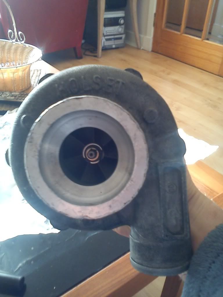
The supercharger is a Holset. Cant find any info about it so I assume its been made up from a Holset turbo blower impellor, half of the blower casing and whatever else to complete it. The only stamp on it is HOLSET on what looks like was a turbo casing at some stage. When it was on the other engine it was running only 0.5 bar max boost. Havent checked the inducer size etc to try to determine the characteristics of it but I'm hoping to just change to a smaller drive pulley to get it to spin faster and blow more. Unless thats a stupid idea??
Would certainly help if you had the details of your supercharger. SFAIK, Holset never made a centrifugal blower, so chances are it’s something with a Holset compressor fitted. I have a sneaky feeling that early Rotrex blowers used Holset compressors, but don't quote me on that!
Without knowing the exact details of your compressor and the gear ratio of the mechanism driving the compressor, you literally have no idea as to whether the compressor will at any point surge or choke. I would honestly suggest that you dedicate some time to finding info on your blower else you will not be the first person to encounter undiagnosed "difficulties". Be warned that a centrifugal blower (much like a turbocharger) is definitely not plug and play.
FYI, Appletree and Rix313 have Rotrex C30-84's on their M42's, and Tim_haynes has a Rotrex C30-94 on his M20B25 pushing 380hp (see here)
HTH and welcome.
Regards
Geoff

"It is amazing how many drivers, even at the Formula-1 level, think that brakes are for slowing the car down." - Mario Andretti

The rotrex did indeed use holset compressors.
-
mongomushroom
- E30 Zone Newbie
- Posts: 163
- Joined: Sun Sep 12, 2010 11:00 pm
- Location: Glasgow/Stornoway
hi, thanks very much for every body's input. Very helpful. Seems that you guys are right about the s/c being rotrex. I found some pictures online of somebodies alfa romeo project and s/c looks like exactly the same setup. I will try to add them. The inducer on mine is about 38mm and i think but not sure the exducer is 62mm. The pulleys fitted at the moment are 160mm drive and 84mm driven. Think its got a reducer gear aswell though!!! When fitted before this was putting out 0.5 bar. I found stamped on the compreesor housing 00 62. The Rotrex c30-94 that i found a photo of has 21 90 stamped in the same place whether that means anything I'm not sure. On the bearing housing I found 1143 01 03 stamped which I assume is a part number. Do any of these numbers make sense to anybody???
coudn't add the photos of the similar 1 i found but maybe try these links http://www.alfaclub.pl/democar/stage2-democar59.jpg http://www.alfaclub.pl/democar/stage2-democar57.jpg
coudn't add the photos of the similar 1 i found but maybe try these links http://www.alfaclub.pl/democar/stage2-democar59.jpg http://www.alfaclub.pl/democar/stage2-democar57.jpg
-
mongomushroom
- E30 Zone Newbie
- Posts: 163
- Joined: Sun Sep 12, 2010 11:00 pm
- Location: Glasgow/Stornoway
Hi, not sure if anybodies following this but I've been in contact with Rotrex and TTS performance who have been very helpful. It seems that my s/c is a 2003 model. Rotrex do not have records anymore but sent me a technical data sheet for the C30 which is what continued the SP30 line. By comparing the dimensions it seems I have an SP30 with either 84 or 94 trim or something imbetween if such a trim existed in the SP30 range.
My project is still in the early stages, some welding, painting, engine rebuilt etc etc to be carried out but will post some pics when I have more to show. If I got anything close to tim haynes's HP I would be extremely happy but anything over 300 HP would do me very nicely 

My project is still in the early stages, some welding, painting, engine rebuilt etc etc to be carried out but will post some pics when I have more to show. If I got anything close to tim haynes's HP I would be extremely happy but anything over 300 HP would do me very nicely
If you can, pull the compressor housing off and measure up the compressor wheel. Then get Rotrex to confirm for you exactly which model you have.
BTW, the trim of the compressor wheel is simply equal to 100 x the square of the inducer dimesion divided by the square of the exducer dimension. For example, if the inducer dimension is 53mm and the exducer dimension is 71mm, then the trim = 100x(53^2)/(71^2) = 100x2809/5041 = trim 56.
If you have a C30-94 then you have the ideal Rotrex for the job. Unfortunately, Rotrex don't publish their wheel dimensions (only housing) on their datasheets (iirc), so you will need their input on this. It is quite possible to have two identical trim wheels, but one to be physically larger (flowing more air) than the other.
HTH
"It is amazing how many drivers, even at the Formula-1 level, think that brakes are for slowing the car down." - Mario Andretti
VERY easily achieved with a C30-94 on an 8.8:1 CR M20B25. Don't forget the intercooler!mongomushroom wrote:... but anything over 300 HP would do me very nicely
"It is amazing how many drivers, even at the Formula-1 level, think that brakes are for slowing the car down." - Mario Andretti
You can have as much boost as you like within the bounds of that defined by the pulley ratio and that which the engine can tolerate without detonating.phelix wrote:What boost level and subsequent power could one get without an intercooler?
It is, however, not boost that makes power, but rather the mass of air flowed into the engine per unit time. Now, because the air through the compressor is compressed, it heats up, and thus its density drops, reducing the mass of air inducted into the engine per unit time. An intercooler is required to remove this heat, thus returning some of the lost density, raising the mass flow rate of air into the engine. An intercooler thus actively contributes to your engines power output. Without one you'll be lucky to make it to much over 220hp before the inducted air is so hot that detonation kicks in. It simply does not make any sense whatsoever to fit any form of compressor without an intercooler given how much power the intercooler contributes for so little extra cash outlay.
"It is amazing how many drivers, even at the Formula-1 level, think that brakes are for slowing the car down." - Mario Andretti
Thanks, all understood - I learned a fair bit about boost levels, turbos, overheated intake air and intercoolers as owner of a twin turbo 911. My M20 application in a Z1 has space constraints and I'm also not looking for mega horsepower.
-
mongomushroom
- E30 Zone Newbie
- Posts: 163
- Joined: Sun Sep 12, 2010 11:00 pm
- Location: Glasgow/Stornoway
I don't want to pull the supercharger apart without knowing if I can get spares for it. Actually I think I would have to take the bearing housing to pieces before getting to the compressor housing. Rotrex and tts told me they are throw away anyway and they cannot supply any spares, but I suppose they would. I can't see any reason why a new set of seals and bearings cannot be sourced but cant be bothered with hassle, got enough to do.
I'm thinking of starting a new thread to identify this baby because I feel I've exhausted all of my available resources without conclusive results and can't help thinking there must be somebody with the same old school unit on this site.
I'm new to the e30 scene and I've got to say I love them. Endless fun thrashing them and great to work on. Just removed an engine and gearbox out of 1, did timing belt, tappet clearances oil, plugs etc and removed another engine and gearbox from another in the last couple of days and have to say to say they are a joy to work on. Very user friendly. Looking forward to building this supercharged engine. Got to get the body, handling etc up to standard and go to work etc in the meantime which is pretty shit but that's reality
Six bolts. Undo them. Remove the compressor housing exposing the compressor wheel and backplate leaving the remainder intact. Put a vernier on wheel and measure. Now measure the throat of the housing. It's that easy. If you don't post up the dimensions of your compressor wheel and housing you'll never know what compressor you have and whether it's suited to your application.mongomushroom wrote:I don't want to pull the supercharger apart without knowing if I can get spares for it. Actually I think I would have to take the bearing housing to pieces before getting to the compressor housing. :
In your new thread you might like to a) post photo's of your compressor and b) actual measurements and you might get a conclusive answer. We're not psychic, and I certainly am not your "resource".mongomushroom wrote:I'm thinking of starting a new thread to identify this baby because I feel I've exhausted all of my available resources without conclusive results
"It is amazing how many drivers, even at the Formula-1 level, think that brakes are for slowing the car down." - Mario Andretti
-
mongomushroom
- E30 Zone Newbie
- Posts: 163
- Joined: Sun Sep 12, 2010 11:00 pm
- Location: Glasgow/Stornoway
Sorry dude, didn't mean to refer to you as a resource. Not great with words and had about 10 or 15 cans of cider yesterday before I posted here. Apologies.
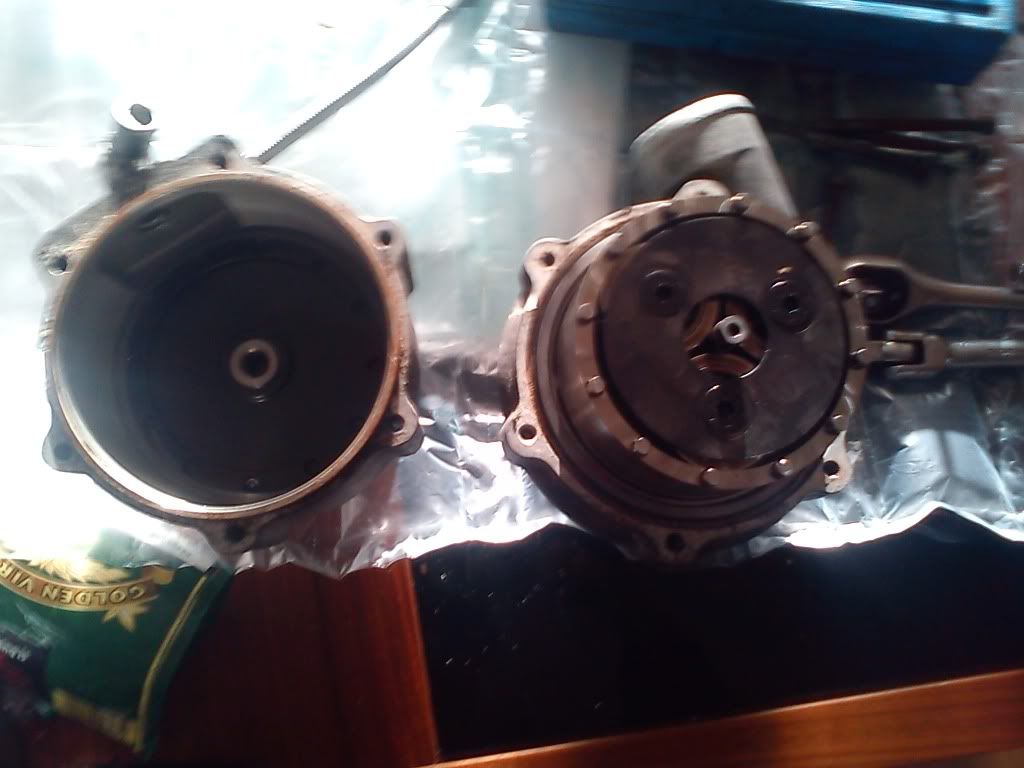
I've undone them 6 bolts and shaft nut but that only allows me to take off the bearing housing with bearings, compressor wheel, backing plate, compressor housing still in place. Not wanting to force anything.
Got some photos here but not sure how to post them! Trying to figure it out now.[/img]
I've undone them 6 bolts and shaft nut but that only allows me to take off the bearing housing with bearings, compressor wheel, backing plate, compressor housing still in place. Not wanting to force anything.
Got some photos here but not sure how to post them! Trying to figure it out now.[/img]
-
Ant
- Retired Team Member

- Posts: 10496
- Joined: Tue Dec 21, 2004 11:00 pm
- Location: PD+E dept :D
- Contact:
remove the compressor housing and measure the largest and smallest dia of the comp wheel, that is the required info dude
the housing will need a gentle tap to release but its designed to be easily removed/rotated to suit the application so you'll not break anything.
as stated 6x m8 bolts-tap and measure
no need to touch the bearings, reduction gear or shaft to wheel nut !!!!!
good luck !
the housing will need a gentle tap to release but its designed to be easily removed/rotated to suit the application so you'll not break anything.
as stated 6x m8 bolts-tap and measure
no need to touch the bearings, reduction gear or shaft to wheel nut !!!!!
good luck !
Product Development and Endurance for Delphi.
Original performance chips, original works not unlicensed copies Email FTW
Original performance chips, original works not unlicensed copies
-
mongomushroom
- E30 Zone Newbie
- Posts: 163
- Joined: Sun Sep 12, 2010 11:00 pm
- Location: Glasgow/Stornoway
cheers ant, couple of taps like you said. 48mm and 72mm so I guess that means a trim of 44. Anybody used a similar supercharger?

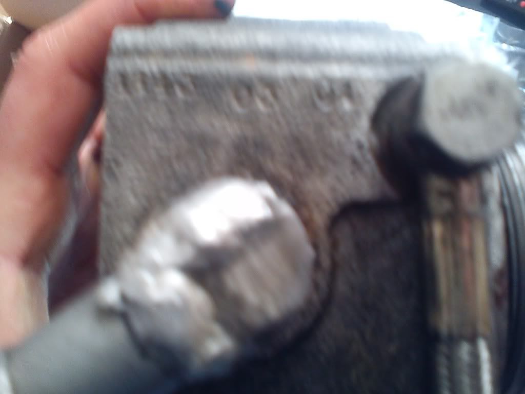
Got it sussed now. The numbers in the last photo are 1143 03 01
Got it sussed now. The numbers in the last photo are 1143 03 01
Last edited by mongomushroom on Wed Dec 22, 2010 2:05 pm, edited 1 time in total.
No harm donemongomushroom wrote:Sorry dude, didn't mean to refer to you as a resource. Not great with words and had about 10 or 15 cans of cider yesterday before I posted here. Apologies.
Good work Mongo. I've contacted Tim_haynes and asked him to have a look at your thread. He has an old S-type Rotrex in his workshop so he'll be able to confirm, but it looks to me as if this is what you have. Take note that (like a turbo) it uses engine oil for lubrication, not "traction fluid" like the modern ones do.mongomushroom wrote:cheers ant, couple of taps like you said. 48mm and 72mm so I guess that means a trim of 44.
Got it sussed now. The numbers in the last photo are 1143 03 01
In the mean time I'll try track down a compressor map for you.
"It is amazing how many drivers, even at the Formula-1 level, think that brakes are for slowing the car down." - Mario Andretti
-
mongomushroom
- E30 Zone Newbie
- Posts: 163
- Joined: Sun Sep 12, 2010 11:00 pm
- Location: Glasgow/Stornoway
Cheers my man, all help very much appreciated.
Mongo,
I hunted high and low last night and the best I can proffer is that your compressor is an old HE30 with a 73mm compressor wheel. Modern HX30's have an 83mm wheel (sfaik), so it can't be one of them (are you sure you measured correctly?). From your pics it looks to me as if someone had a go at machining the eye/throat of the compressor, so I guess it's possible you have something totally custom on your hands and, unless you make contact with the person who made it, you'll likely never know what it is. Disappointingly, the Holset ID tag (which should be next to your wrist in the above pic) is clearly missing.
To avoid tears in the future, my honest suggestion to you would be to get in touch with TTS and have them replace the compressor wheel and housing with items from a C30-94. The important and expensive bit (the gears) you already have, and replacing the compressor wheel and compressor housing should not be an expensive exercise. A quick measure of the bolt spacing will confirm if the housing from a C30-94 will bolt in place. The fundamental design hasn't changed so I don't see why not.
BTW, I would not recommend an HE30 (if that is indeed what you have) as it's flow-map is similar to that of the C30-84, and is better suited to a 1800cc to 2200cc engine (this is what Appletree and Rix313 have on their 1800cc M42's).
One further task you can attempt in identifying your Rotrex is to determine the gear ratio of the drive mechanism. You do this by counting, while turning by hand, the number of turns of the compressor wheel, while someone else simultaneously counts the number of turns of the pulley. If you have something that is related to the C30 series then you’ll need to turn the compressor wheel 9 a revolutions for the pulley to make one complete turn. The C38 series, however, requires 7 a turns of the compressor wheel for every one turn of the pulley. You will need to know this so that you can determine your required pulley sizes. Take note that a centrifugal blower doesn’t produce a constant amount of boost (like a turbo which is regulated by it’s wastegate). A centrifugal blower produces boost that rises in direct proportion to your engine speed. IE: more rpm = more boost. Getting your gearing and pulley sizes correct is important as you can easily wind up making too much or not enough boost. Even worse, you spin the Rotrex too fast and then it breaks.
HTH
"It is amazing how many drivers, even at the Formula-1 level, think that brakes are for slowing the car down." - Mario Andretti
-
mongomushroom
- E30 Zone Newbie
- Posts: 163
- Joined: Sun Sep 12, 2010 11:00 pm
- Location: Glasgow/Stornoway
Thanks again for your efforts Geoffbob. Think it actually is 73mm. Wasn't sure wheather to take the measurements from the largest measurement across the blades or the diameter of the plate. I might actually look into what you were saying about changing the impellor and housing although TTS have told me that these units are throw away and spares aren't available. Could possibly use an old turbo for this but will need to look more into it at some stage. A turbo compressor housing can't be too hard to machine. I'm actually working offshore at the moment untill after New year and didn't bring the charger with me so I can't do much else about it now.
If I can figure out what the max rpm of the unit is and calculate the pulley size to suit I could see if it is much different to what's fitted at the moment. If its running at its lowest possible rpm as it is I could get a reasonable enough gain in power with just changing the pulley ratio (of course without overspeeding it) and think about fitting a C30-94 or similar at a later stage. I saw on Tim_haynes's thread that he didnt drop the compression ratio much to accomodate C30-94 so I wouldnt need to do any intrusive engine work to change superchargers, only mapping etc. Still a while off before I need to think about it anyway.
Thanks for everything mate, Merry Christmas
At a guess I'd say the labour to machine a housing would be more than buying a new one. The fundamental design of the Rotrex gear unit has not changed (sfaik?). I have no doubt they would like to sell you a whole new one, but I personally wouldn't bother if the parts are identical/interchangeable. I would, however, suggest being cautious with regard to the compressor. Changing pulley ratios physically changes where the compressor will operate on its flow-map. Speeding up a Rotrex (in relation to engine rpm) moves the load-line closer to the left-hand side of the flow map, that is to say, towards surge. A compressor that is too big for an application (say a C30-94 on a 1600cc engine) can't be made to work by speeding it up since it just goes into surge and eventually destroys itself. The converse is true if the compressor is too small (say a C30-64 on a 2500cc engine) which will have to be slowed down to stop it from over-boosting the engine, shifting the load-line to the right, potentially choking the compressor. Neither option works particularly well ”“ it really is a case of finding the Goldilocks solution that fits your engine.
Unfortunately, without a well defined flow map at your finger tips you will literally be left guessing as to how it will perform and you may need to experiment with pulley ratios on the car and/or change the compressor at some point. I guess this is why I prefer to start with a well defined compressor (supplied with flow-map) so that I can get it right from the outset.
BTW, have a look here at the work I did for Appletree. The results won’t apply (different engine and compressor) but the method of finding one to work on your engine is exactly the same.
Oh, and Tim_Haynes engine is a stock 8.8:1 compression ratio M20B25 (sfaik), but he does run it on race fuel to prevent detonation. On pump fuel you’ll likely need a bigger Rotrex pulley (to slow it down) or you’ll likely run into detonation at >1bar boost.
Merry Christmas to you too mate. All the best for your duration off-shore.
"It is amazing how many drivers, even at the Formula-1 level, think that brakes are for slowing the car down." - Mario Andretti
You can stay away from surge by altering the inlet density using a throttle plate.
This can be accomplished in may ways, electronically and mechanically.
This can be accomplished in may ways, electronically and mechanically.
-
mongomushroom
- E30 Zone Newbie
- Posts: 163
- Joined: Sun Sep 12, 2010 11:00 pm
- Location: Glasgow/Stornoway
Hmm not so simple either way. Thats some pretty awsome stuff GeoffBob. Seems that you're a bit of a wizard. I'll have a proper read when I've got some vodka!!
What I know about the charger is that it was running 0.5 bar boost on what I'm pretty sure was a 2.7 M20 producing 201 rwhp and 298ftlb. Seems like a very modest power output which makes me think that the chargers not up to the job even if I could get a bar boost. Not sure what all other extras the engine had but I do know it had 7th injector with MF2, shrick cam (unsure of profile) and piggy back ecu. I've got copies of the rolling road results somewhere and if anybodies interested I can scan them on after I get back in a couple of weeks.
I'll need to look more into all of this. Got a pile of recipts somewhere that I'll need to look through again to see if I can find any clues but as far as I remember there was nothing about the kit. The guy I bought everything of didn't know much about the supercharger and I don't think he's in contact with the guy he bought it of either. I'll see if modifying a turbo compressor housing is an easy enough option aswell. If its a case of some drilling, tapping and some not so drastic machining it could be a very good option but like I say I'll need to look into it.
I'll need to do a little research for my own sake aswell. I'm used to large marine diesel engines not performance petrol engines so I'll have to do a little reading first. What is a throttle plate BTW and do you have any information on how it works?
Hallo Gunni and Merry Christmas.Gunni wrote:You can stay away from surge by altering the inlet density using a throttle plate.
This can be accomplished in may ways, electronically and mechanically.
Unfortunately it is "surge under load" to which I refer and not the surge that develops when you lift off the throttle. I take it as written that a recirculation or blow off valve (electronically or mechanically controlled) is mandatory on a supercharged engine. Without one the air flow through the compressor will reverse direction (surge). "Surge under load" is where the load-line (plotted on the compressor flow map) literally crosses over the surge line at some point. It is as a result of the fact the compressor wheel is too big to maintain the demanded pressure ratio (dictated by the compressor wheel speed, geared to the crank) at the value of air flow dictated by the engine operated at that pressure. It is characterised by a barking/growling noise as the air-flow around the compressor blades becomes turbulent and oscillates back and forth. It eventually destroys bearings and can fatigue compressor blades (at the extreme) to the point where they fail.
"It is amazing how many drivers, even at the Formula-1 level, think that brakes are for slowing the car down." - Mario Andretti
If you lower the pressure infront of the compressor via throttle you raise the pressure ratio again (to the right on the flow map across the surge line)
I.e
let say we are seeing 120kpa after the compressor and before engines throttle.
And lets assume that surge will occur at 1.2 pressure ratio on a X compressor setup at X speed.
If you lower the inlet pressure to the compressor to say 60kpa, the pressure ratio is now 2.0 but the outlet is still 120kpa. And assumed is that this compressor at X speed does not surge at 2.0 PR
Keeping the compressor outlet pressure fixed (at say 120kpa, as in your example) means that the mass air-flow into the engine is fixed at that engine rpm, and so what you describe moves the compressor operating point (plotted on the compressor flow map) vertically upwards (not to the right). What you describe will, therefore, push the compressor further into surge.Gunni wrote:let say we are seeing 120kpa after the compressor and before engines throttle.
And lets assume that surge will occur at 1.2 pressure ratio on a X compressor setup at X speed.
If you lower the inlet pressure to the compressor to say 60kpa, the pressure ratio is now 2.0 but the outlet is still 120kpa. And assumed is that this compressor at X speed does not surge at 2.0 PR
"It is amazing how many drivers, even at the Formula-1 level, think that brakes are for slowing the car down." - Mario Andretti
Without any testing it would not be sure what would occur by lowering pressure infront of the compressor.
When you think about it, the pressure after would probably drop anyway.
When you think about it, the pressure after would probably drop anyway.
The theory is quite clear on how the compressor will behave and is in accordance with that observed in practice.Gunni wrote:Without any testing it would not be sure what would occur by lowering pressure in front of the compressor.
When you think about it, the pressure after would probably drop anyway.
Lowering the intake pressure (while maintaining the same pressure ratio) will lower the pressure at the outlet, thus reducing (throttling) the flow of air into the engine. The operating point will thus move to the left (deeper into surge).
As before (your suggestion), lowering the intake pressure (while raising the pressure ratio in order to maintain the outlet pressure) will maintain the airflow into the engine, and will thus move the operating point upwards (also deeper into surge).
"It is amazing how many drivers, even at the Formula-1 level, think that brakes are for slowing the car down." - Mario Andretti