Lashing up an exhaust

All the info you need to race E30's

Moderator: martauto

Post Reply
Jon_Bmw
Dangerous when thinking
Posts: 7606
Joined: Tue Jan 11, 2005 11:00 pm
Location: Salisbury

Wed Dec 17, 2014 9:46 pm

I know it is for a 205, but it might be of interest to some:

This isn't complete yet(the write up or the actual thing), because I am lazy and when you work with exhausts, yours is always the last in a long line of well paying customers! I have used library photos for now whilst watching a footie match on tv. I will try and replace them with the real thing one day...


Part 1:


Exhausts can be made in a few ways”¦.

CAD it: make a fixture/jig in CAD using cust supplied CAD model of exhaust, produce the fixture and make the exhaust in the fixture.
Reverse Engineer it: Basically starting with someone else’s exhaust. Build a jig around it and re produce the exhaust in the fixture
Guess it?: I think this is how most custom places do it”¦ Bodging stuff on cars basically using off the shelf bends, straights and resonators. It is common to see pressure bent tube and multiple joints. Nasty.

Anyhow, as this is for a sub £4k 205, and I am a tight fucker we are going to mix and mash all three ways together using some of the gear at my disposal at work.

If for any reason you read this lot, you don’t fall asleep, and you can ignore all the lashing up and general bodgery and you decide that JON_BMW could help you lash something onto your E30, please think again! I am too busy to do it, and have no inclination of making my work life any more stressful for a few beer tokens! To give you an idea after all the fannying about and doing sod all it will have probably taken 6-9 months to get it on the car. I don’t want someone (like pony!) phoning me every ten minutes about some bodged up exhaust.


Background:
205 Gti with 16V 1905CC engine (mi16). Circa 160wheel HP. Car requires 4 branch manifold and larger bore exhaust. Currently has ”a8 branch”a standard manifold and circa 2”a pressure bent exhaust system.

Image

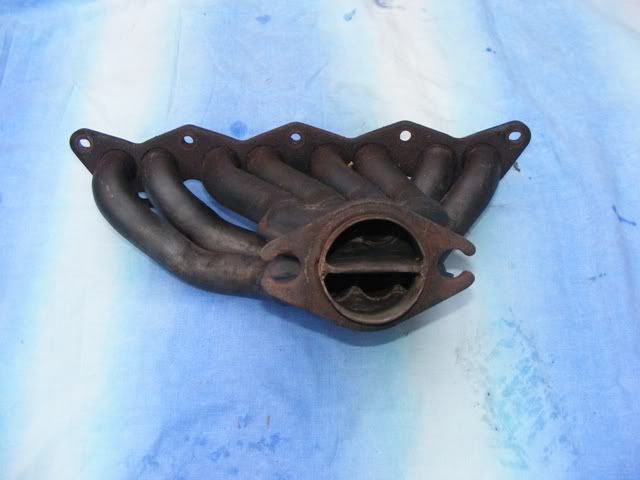
Being tight I found an old manifold on the 205 forum. What a nightmare, even working at my incredibly slow pace it would have been easier making something from scratch. This thing was shite and required hefty rework(read big hammer, air saws and lots of swearing). It came with what can only be described as a JOKE of a collector. This thing had been welded up by someone with even less skills than me. That is saying something!
So fastforward on about 6 months after I bought the manifold it was test fitted onto a cylinder head at work and one of the lads made me a proper 2 into 1 merge collector. This was fully purge welded and is what you need. None of this pressed 2 into 1 collector nonsense. Library pictures attached at the moment!


Image

Image


So to the conundrum, what to do with the scabby ”˜custom’ type exhaust that was on the car?
The routing was essentially good with acceptable clearance. The noise level in the early days was pretty good at around 88DB. The pipework was the usual pressure bent crap that custom places offer. This is for two reasons; ease of work and time. To setup a Mandrel Bender on a different size tube takes anything from 0.5-3hours depending on the machine. To setup some shite Ben Pearmon pressure bender, takes about 5 mins! So when doing custom work, guess which type of bends they offer, most of these places don’t even have a mandrel bender!

The centre resonator (ressy) was borked, with the exhaust wrap(E Glass) overheated and balled in the resonator. Shake the ressy and it would rattle bad. No wonder the car was getting louder and louder at successive track days! It also occasionally spat out of a bit of E glass”¦hmm I wonder why????

The rear resonator must have been made by Stevie wonder. Firstly, the tailpipe”¦OMG what were they thinking, it is about 80mm rolled out. Yikes! Secondly the perforated tube inside the resonator is not in line with the inlet pipe. It is basically eye-lidding and has raw edges all over the shot, something you do not want the exhaust gases hitting. This was also the reason it spat out E Glass once in a while. All very embarrassing, especially when someone, somewhere down the line probably got bent over for £400 for it! Ouch.

The bits I could use then was basically the routing path and the resonator size to hopefully keep under 95DB and that was pretty much it.

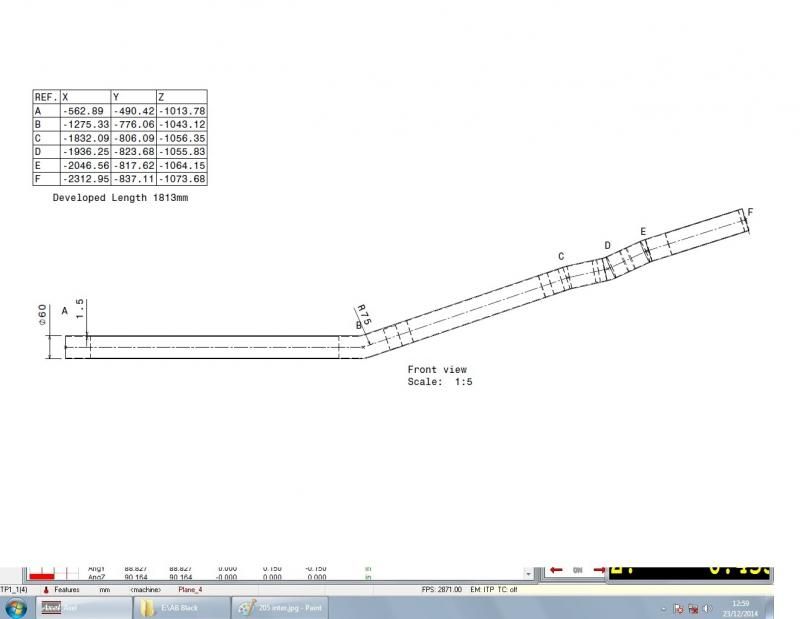
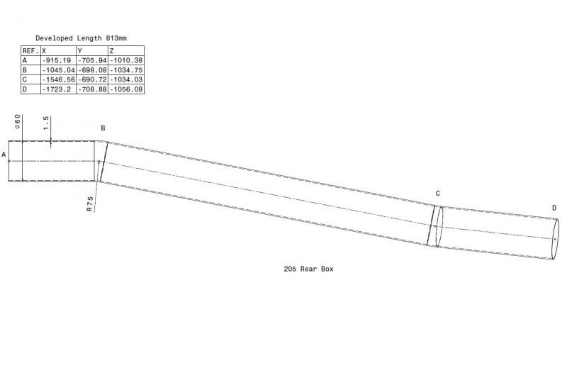
So the first thing I did was used our co-ordinate measuring machine (CMM) at work to measure the two exhaust sections I had.
Our CMM is a manual one at work, so requires a reasonable amount of skill and good hand to eye co-ordination to avoid smashing up the £3k probe. Why I am the main user of it in our place”¦god only knows! It basically looks something like this(but manual) with a flat bed on it:

Image


Our CMM is reasonably large because we have to measure exhausts that can be 2500x1200x 800mm in size. Our machine can measure up to 3000 x 1500 x 1500 IIRC.

So you place the exhaust on the table and clamp it in place so that it doesn’t move. You don’t want the part moving whilst you are measuring it, for obvious reason. Then using a probe, like the one below you hit various points on the exhaust to replicate the straights, resonators, inlet and outlet points, hanger brackets etc etc.

Image

The probe is able to move in the ”aA angle”a from straight down to 97.5 degrees. And in ”aB”a it can spin around the whole 360 degrees. This enables you to measure complex parts. You can also change to a smaller or larger styli’ (the red bit at the end) as well as being able to add extensions and other trick bits. For our simple exhaust I could measure pretty much everything with the (0,0) position. That is to say that angle A and B are both at ”azero”a degrees.

The bend software is quite clever, normally you can measure the straights and it will work at the XYZ’s and YBCs of the bends if you can tell it the Centre Line Radius(CLR). As this is pressure bent shit and I am unware of what tooling was used I can’t tell it this. So for the time being all I am interested in doing is measuring straights, resonator boxes, inlet point, outlet point and hanger brackets (basically straights again).

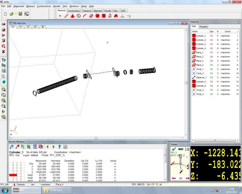
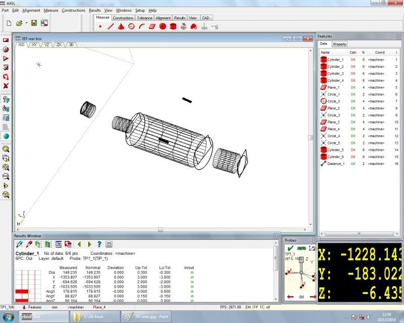
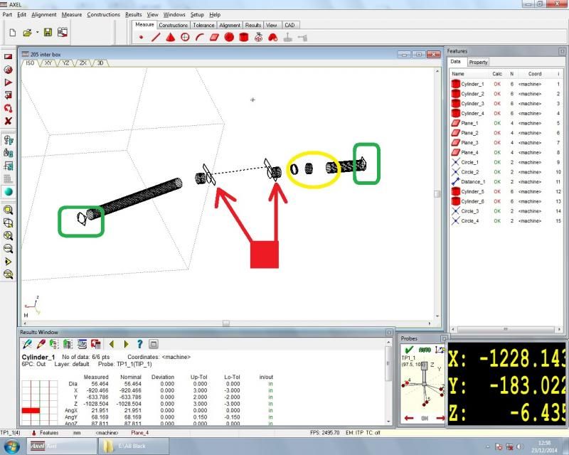
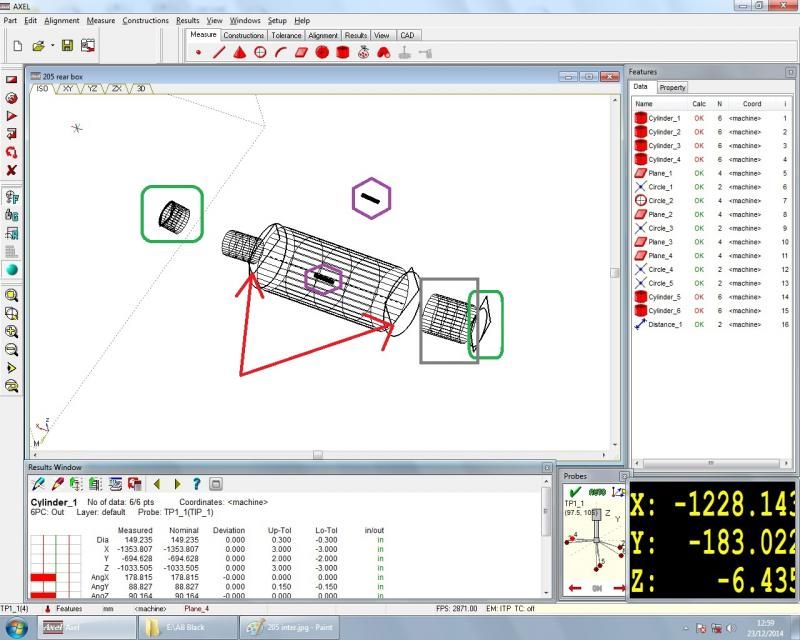
You end up with something like this on screen:

PART 2 to follow when more enthusiasm arrives and I have the screenshot from the machine at work!
User avatar
Kos
E30 Zone Team Member
Posts: 15546
Joined: Tue Jul 12, 2005 11:00 pm
Location: London / Cyprus
Contact:

Wed Dec 17, 2014 10:22 pm

Subscribed :D
PUKAR DESIGNS - Reproduction BMW Decals Labels Sticker & Number Plates
www.pukardesigns.com
www.facebook.com/pukar.designs/
IG Pukar.Designs
Rav335uk
E30 Zone Meets/Events Team
Posts: 27985
Joined: Wed Jan 19, 2005 11:00 pm
Location: Mad mad mad
Contact:

Thu Dec 18, 2014 12:20 am

Watching, why?? I don't fooking know yet. :D
Image
If you Got "Haters",Then your doing something Right!
CR24v??? Where's it all gone?? LOL
Demlotcrew
E30 Zone Team Member
Posts: 13329
Joined: Mon Dec 20, 2004 11:00 pm
Location: East Anglia

Fri Dec 19, 2014 5:30 pm

Jon_Bmw wrote:If for any reason you read this lot, you don’t fall asleep, and you can ignore all the lashing up and general bodgery and you decide that JON_BMW could help you lash something onto your E30, please think again! I am too busy to do it, and have no inclination of making my work life any more stressful for a few beer tokens!
:giggle:

Subscribed.
maxfield
Old Skooler
Old Skooler
Posts: 15186
Joined: Sat Nov 26, 2005 11:00 pm
Location: Mansfield

Fri Dec 19, 2014 5:49 pm

Subscribed.

The bit about Pony did make me smile.
Image
Jon_Bmw
Dangerous when thinking
Posts: 7606
Joined: Tue Jan 11, 2005 11:00 pm
Location: Salisbury

Wed Dec 31, 2014 4:56 pm

Part 2:

So remembering what I said about the CMM being able to measure straight bits of tube only you end up with something like this on your screen:

Inter Pipe:

Image

Rear Section:

Image


I have attached these two photos to explain what each bit is, although it is fairly obvious:

Image

Image

Green boxes:

These are basically the inlet and outlet point of both Intermediate and rear sections. The square on the end is the plane, where I take 4 measurements on the bit of tube. The start and stop points basically of my exhaust.


Red Arrows:

These are two further planes taken on each resonator end plate. From this I am able to work out the length and position of the resonators. You can see on the rear box as it was a round resonator I also measured a cylinder around it. This gives me the diameter of it. As the inter resonator is an oval, I cannot measure a cylinder obviously. In real life we can measure arcs and other such things to replicate this, but seeing as I was measuring in company time whilst ”˜training’ a work experience lad I thought I better not take the piss”¦ ”˜Training’ the work experience boy also gives me a get out clause for when none of it fits together”¦


Yellow circle:

Here you can see there was a kink in the pipe on the intersection. This was to miss the gear linkage from memory”¦ Now if you notice the straight length is tiny on my measurements. I always try and measure the longest available measurements to improve the accuracy of the results, but these straights really are that short. This is the classic way to tell (with 99% certainty) that something is pressure bent. For a mandrel bender to work, the clamp which get this, clamps the pipe against the former normally has to be a minimum of 50mm (normally 90mm>). The clamp only works on straight tube”¦.UNLESS you have a very expensive, and bend specific compound clamp, then you do not need any straight length. This sort of tooling is very expensive and useful for doing one job, so it really is an OEM thing only. They are the only ones with the money and the volume to justify a tool, not ”˜Billy I’ll have a go at custom exhausts this week.’ I will try and get some photos of the bender and bend tooling (inc compound clamps) that we have at work as a picture paints a 1000 words, especially ones being written down as badly as this.


Grey Box:

This was the hideous rolled out tailpipe that was on the car. God it was big, but at least it didn’t hang off. I had another 205 that has some hateful magnex on that nearly did me and my brother an injury once. It was large and stuck out about 150mm. Whilst manoeuvring behind the car in a dark garage I nearly broke my leg tripping over it, whilst my brother split his sides laughing. Bastaaaard, and the fucking exhaust was terrible.


Purple Hexagons (I have paint 2013, and I am desperate to fully utilise it, can you tell?):

This are cylinder measurements. These are where the rubbers sit on the exhaust on the rear box. This was done purely as a training thing for the new boy. I will build these on the car as if you remember I am not producing a fixture up to make this exhaust.

My goal of measuring the exhaust was to replicate the pipework keeping as few welds as possible on the exhaust (to ensure the best strength possible for the next time it is entering a gravel trap backwards at 90mph). So anyway, I export my measurements into an IGS file and give them to one of the CAD chaps at work. He is easily bought with Chocolate Oranges and any food. He works on Catia v5, I think it is a program about pussies, but it is far too complicated for simpleton like me to worry about. He comes back with the following:

Image

Image

Yay a couple of bend drawings. So from my measurements that I worked out, I have given him a tube size and bend radius that I know we have tooling for and he has done some jiggery pokery and other magic and produced these. So the tube size I have gone for is 60mm OD with a 1.5mm wall using the 75mm CLR Former. I would normally have used 1.2 wall for added lightness, but alas there was no 304 stainless steel in the tube store in 1.2 mm. 60mm is probably overkill, but our tooling for 2.25”a is quite worn and doesn’t produce such nice results as brand new tooling ïaŠ We also have in stock 60mm 304 stainless perf that has been lying around for a while”¦ Normally most exhaust manufacturers, ourselves included, use 409 stainless perf for cost reasons. Because the car does not get used that often condensation will sit in the resonators for month after month. I don’t particularly want it rusting from the inside out.

If you pay particular attention to the interpipe around where the gear linkage would be(roughly points C, D, E on the drawing), this is where the CAD lad had to do his jiggery pokery to give us the clamp length (90mm) that we need to produce the bends on the Mandrel Bender. He used the space that we measured and our tooling clamp lengths to come up with this. Should work ”¦. Haha. The XYZs will be used by the benders”¦

You will also notice there is a fair section of straight on both sections. Because I am lazy, and not concerned by waste tube on this (I was concerned about my time though!) we will chop out the appropriate length for the resonator to sit. This means that this exhaust will only have 4 structural welds on it (exc hanger brackets) , the inlet to the front reso, the outlet from the front reso, the inlet to the rear muffler, the outlet from the rear reso. All part of the plan to reduce the amount of welding.


Part 3: All things Benders.

To follow.
Demlotcrew
E30 Zone Team Member
Posts: 13329
Joined: Mon Dec 20, 2004 11:00 pm
Location: East Anglia

Fri Jan 02, 2015 11:16 am

Brilliant, dont keep us waiting too long :)
Post Reply