

You cease to amaze me... now your making your own carbon fibre moulds, that is what I call workmanship!
Well done.
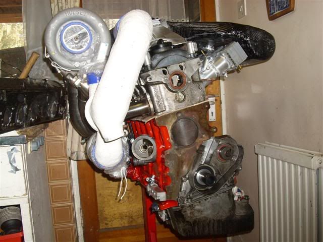
Twin Seq. Dry sumping for beginners :D
Moderator: martauto
-
rix313
- E30 Zone Team Member

- Posts: 4967
- Joined: Fri Oct 31, 2008 11:00 pm
- Location: Silverstone
Nice one! I looked (very breifly) into carbon pipe work at my old job but was concerned about the heat of the charge air, melting the resin.
Too right about your warning with the chemicals, the release agents we used would make you vommit with out realising.
Can't wait to see them.
Too right about your warning with the chemicals, the release agents we used would make you vommit with out realising.
Can't wait to see them.
-
Turbo-Brown
- Boost Junkie
- Posts: 4705
- Joined: Tue Feb 15, 2005 11:00 pm
- Location: Aldershot, Hants
Blimey, that does sound unpleasant! I just use PVA release stuff which is pretty harmless, or release wax from TR which again isn't hazardous.....or for something like the flanges on the pipework there, just rubbed a candle over the sheet of aluminium.
The charge air shouldn't be getting up to more than 40or so degrees so I wouldn't have thought it'd cause any problems for the resin. My biggest fear was that the heat from the exhaust would scorch the pipes so it was a relief to find fire retardant resin. Throw some heat shields in and we should be laughing
The charge air shouldn't be getting up to more than 40or so degrees so I wouldn't have thought it'd cause any problems for the resin. My biggest fear was that the heat from the exhaust would scorch the pipes so it was a relief to find fire retardant resin. Throw some heat shields in and we should be laughing
-
gareth
- E30 Zone Team Member
- Posts: 11009
- Joined: Tue Jan 11, 2005 11:00 pm
- Location: hastings, east sussex
oh the sunroof is definately getting binned!Jon_Bmw wrote:Sunroof(if you have one? most didgareth wrote:this will amuse you alex... me and my bro are putting together a puglet 205 gti track plaything with the lighter 106gti 1.6 16v TU series engine. last weekend we were stripping uneccesary weight out to the point the dashboard is now gone, and removing obsolete wiring (heavy stuff!) for all electric stuff that's since been binned. we were thinking about carbon interior door panels but got put off by the price. so we started some lateral thinking (dangerous!), this led us onto glass fibre but we can't find anyone who will sell 1mm sheets yet... more lateral thinking... polycarbonate, polypropylene etc all considered, then we stumbled upon a site that can supply very large and cheap sheets of tufnol in various thicknesses! that amuses the sad engineer that lurks within me and is definately retro! similar in principle to glass/carbon fibre but a lot more old skool! samples will be on order soon) weighs around 14 kilos, you can plate that saving around 10-12 kilos dependant on thickness. Right at the top of the car too.
There was a 106 rallye with a gti engine in it at the recent trackday. All very nicely done unlike our abortion, but he couldn't keep pace with the mi16.
regarding out and out power, that's not the main concern for this car. light weight chuckability is what we're loking for. i stand by the fact the fairly well sorted 205 XS i owned was a lot more fun to throw around than either of my 205 GTi's. the lighter engine should allow for a seriously lightweight car once we're done.
slightly more on-topic... looks like you've been having fun alex! I might have to start knocking up lightweight bits for the 205 now! CF dash anyone?
Sole founder of Fe2O3-12V it's a lifestyle

LSD rebuilding / modification services provided, PM for details
LSD rebuilding / modification services provided, PM for details
-
Turbo-Brown
- Boost Junkie
- Posts: 4705
- Joined: Tue Feb 15, 2005 11:00 pm
- Location: Aldershot, Hants
Give it a go dude, it's surprisingly easy once you've had a couple of attempts at it 
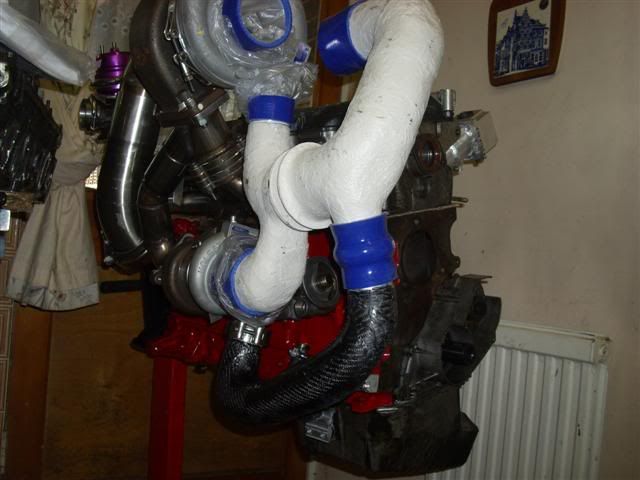
Trimmed up the bits of pipe and the two halves of the charge cooler today.
Need to think carefully about how to attach the cooler halves to the core. I reckon a CF plate top and bottom to give a good overlap would do it, and then bond onto the alloy side cheeks.
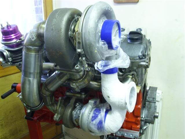
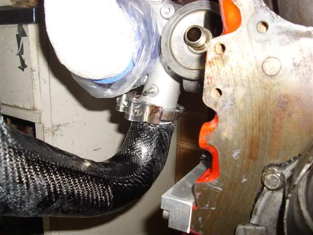
Definately needs some heat shielding here, but it's got about 25mm clearance, and the same thing happens up at the charge cooler where it runs close to the exhaust turbine housing.
Need to get on and fit all the junk that goes on the front of the engine so that I can get a better feel for where the actuators should go. Does look at the moment like they can both live at the front of the engine where it's a bit cooler and they're not in the way of the spark plugs!
Trimmed up the bits of pipe and the two halves of the charge cooler today.
Need to think carefully about how to attach the cooler halves to the core. I reckon a CF plate top and bottom to give a good overlap would do it, and then bond onto the alloy side cheeks.
Definately needs some heat shielding here, but it's got about 25mm clearance, and the same thing happens up at the charge cooler where it runs close to the exhaust turbine housing.
Need to get on and fit all the junk that goes on the front of the engine so that I can get a better feel for where the actuators should go. Does look at the moment like they can both live at the front of the engine where it's a bit cooler and they're not in the way of the spark plugs!
-
Speedtouch
- Old Skooler

- Posts: 14099
- Joined: Tue Feb 14, 2006 11:00 pm
- Location: Canterbury
Looking fab, can't wait to see this installed and running 
///M aurice
ECU Upgrade EPROM Chips, £40 posted within the UK. Note these are not Zone chips.
viewtopic.php?f=6&t=279421
ECU Upgrade EPROM Chips, £40 posted within the UK. Note these are not Zone chips.
viewtopic.php?f=6&t=279421
-
Turbo-Brown
- Boost Junkie
- Posts: 4705
- Joined: Tue Feb 15, 2005 11:00 pm
- Location: Aldershot, Hants
Cheers dude, can't wait myself! Getting there slowly though 
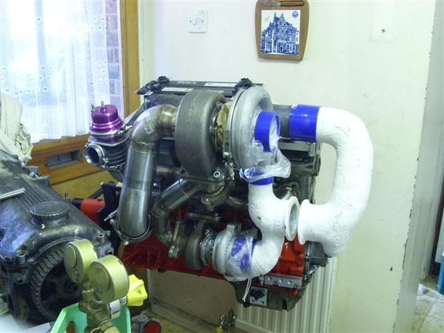
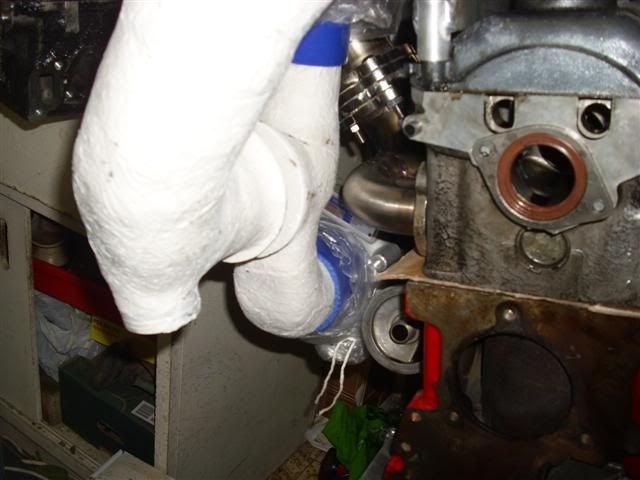
Didn't get an awful lot done today, just spent about an hour and a half clocking the little turbo bearing section and then made up an outlet connection for it.
The outlet from the compressor is a neat little V-band jobbie so it makes sense to have a V-band attachment for the bypass pipe.
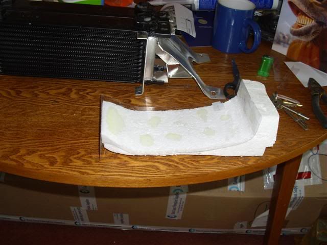
Just gotta make up the foam core for the bypass pipe which carries air up to the little spigot in the foreground of the piccy here:
There's a bit of a twist needed in the bypass pipe as I hadn't reckoned on the oil cooler pipes being where they are, but it's no biggie I don't think
Didn't get an awful lot done today, just spent about an hour and a half clocking the little turbo bearing section and then made up an outlet connection for it.
The outlet from the compressor is a neat little V-band jobbie so it makes sense to have a V-band attachment for the bypass pipe.
Just gotta make up the foam core for the bypass pipe which carries air up to the little spigot in the foreground of the piccy here:
There's a bit of a twist needed in the bypass pipe as I hadn't reckoned on the oil cooler pipes being where they are, but it's no biggie I don't think
-
baptie0

- E30 Zone Regular

- Posts: 624
- Joined: Tue Sep 25, 2007 11:00 pm
- Location: lochinver,scotland.
nice one alex, your doing a great job there, your engine looks brilliant.
-
Coyote_ar
- E30 Zone Newbie

- Posts: 108
- Joined: Mon Jan 07, 2008 11:00 pm
- Location: Argentina
Man thats an amazing job. Just one question, will you be able to change the sparkplugs without having to dissasemble the complete exhaust/intake piping?
-
UweM3
- E30 Zone Squatter

- Posts: 1657
- Joined: Sun Jul 03, 2005 11:00 pm
I raise my hat! You are an inspiration. Just shows what one can do with the right dedication.
-
jaistanley
- E30 Zone Addict

- Posts: 2517
- Joined: Tue Jan 18, 2005 11:00 pm
- Location: Coventry and Essex
Another cap doffing post here dude... That is some serious dedication and hard work right there. I can see myself building a lost foam airbox for my S50 at some point in the future, your guide is fantastic!
Have you considered using vacum baging? You could use those clothes tidy vacum bags, March109 (gareth) was telling me about this. It'd help you get all of the air out of the weave when the resin is setting wouldn't it?
Keep up the good work! When i have a hangover I rarely feel like writing up a how to for people!! LOL.
Jai

-
Turbo-Brown
- Boost Junkie
- Posts: 4705
- Joined: Tue Feb 15, 2005 11:00 pm
- Location: Aldershot, Hants
Cheers guys, very much appreciated indeed!
I had a quick look at the weekend at replacing the spark plugs as it happens. I think the charge cooler might have to come off to replace the plugs, but if I can get the exhaust divertor's actuator at the front of the engine that should be it....hopefully
I read about somebody using a vac bag with a foam core, he recommended against it as the vacuum caused the foam to compress and rucks to form in the cloth
As long as you're careful and can take your time it's possible to get 99% of the air out of a laminate just with a brush.
Think where vacuum consolidation really comes into it's own is where you've got lots of tight / compound curves.
Just one more thought, you shouldn't really use vacuum consolidation with polyester resin as it sucks something or other out of it which needs to be there....apparently
What'll be really interesting is making the front wings without vacuum bagging. There are all mannor of tight and compound curves to be made, but I've got a plan which I'm confident will work where the laminate will be mechanically compressed in the mould by a matching inner former.
-
UweM3
- E30 Zone Squatter
- Posts: 1657
- Joined: Sun Jul 03, 2005 11:00 pm
I have just finished reading a small booklet about vacuum bagging and it has put me off a little bit to be honest. A lot of (expensive) gear to buy in the first place just to have a play.Turbo-Brown wrote:Cheers guys, very much appreciated indeed!
I had a quick look at the weekend at replacing the spark plugs as it happens. I think the charge cooler might have to come off to replace the plugs, but if I can get the exhaust divertor's actuator at the front of the engine that should be it....hopefully
I read about somebody using a vac bag with a foam core, he recommended against it as the vacuum caused the foam to compress and rucks to form in the cloth
As long as you're careful and can take your time it's possible to get 99% of the air out of a laminate just with a brush.
Think where vacuum consolidation really comes into it's own is where you've got lots of tight / compound curves.
Just one more thought, you shouldn't really use vacuum consolidation with polyester resin as it sucks something or other out of it which needs to be there....apparently
What'll be really interesting is making the front wings without vacuum bagging. There are all mannor of tight and compound curves to be made, but I've got a plan which I'm confident will work where the laminate will be mechanically compressed in the mould by a matching inner former.
And I am sure there will be a lot more of trial and error to get it right than wet layup.
-
Turbo-Brown
- Boost Junkie
- Posts: 4705
- Joined: Tue Feb 15, 2005 11:00 pm
- Location: Aldershot, Hants
Yeah, there's expensive kit to buy, and I'm not sure I could properly lay up something the size of a bonnet and then get it into a bag before it starts to gel....plus you have to use the much more expensive resin, and then you have to UV protect that on top!
-
initial_g
- E30 Zone Moderator
- Posts: 975
- Joined: Fri Oct 24, 2008 11:00 pm
- Location: derby
a set of doorcards, just flat would be o.k tho pressed between two mirrors?
-
Turbo-Brown
- Boost Junkie
- Posts: 4705
- Joined: Tue Feb 15, 2005 11:00 pm
- Location: Aldershot, Hants
Yeah, laying sheets of stuff up on something flat is dead easy. Either use something else flat, as you suggest, to keep pressure on, or do what I do which is to get one of those bed-roll things from Millets and then weigh that down with a plastic bin-liner inbetween.
Word of caution with laying up on glass though, it might well break when you come to release your laminate, especially if the glass is thin and the laminate large.
Don't forget to put release agent on the mirror or whatever too
Word of caution with laying up on glass though, it might well break when you come to release your laminate, especially if the glass is thin and the laminate large.
Don't forget to put release agent on the mirror or whatever too
-
initial_g
- E30 Zone Moderator
- Posts: 975
- Joined: Fri Oct 24, 2008 11:00 pm
- Location: derby
sound ive got loads of releasing agents ect (made loads out of fibreglass) i just want to make door cards rear 1/4 cards, and a airbox
cheers g
cheers g
-
Turbo-Brown
- Boost Junkie
- Posts: 4705
- Joined: Tue Feb 15, 2005 11:00 pm
- Location: Aldershot, Hants
You could probably make some lovely sculpted door cards with the lost foam method there, although I suppose they're quite flat as standard aren't they.
-
toecutter666
- E30 Zone Regular
- Posts: 834
- Joined: Thu Feb 21, 2008 11:00 pm
- Location: bedfordshire
I need a fix of twin turbo goodness, has anything more happened to the beast
-
Turbo-Brown
- Boost Junkie
- Posts: 4705
- Joined: Tue Feb 15, 2005 11:00 pm
- Location: Aldershot, Hants
Nothing interesting has happened lately I'm afraid.
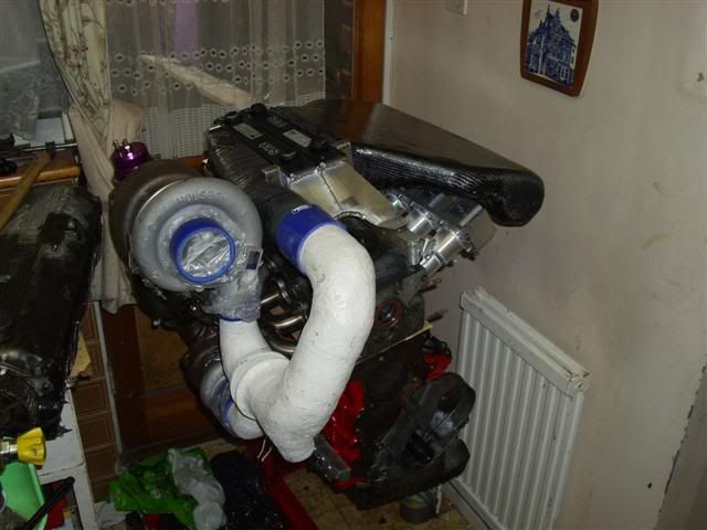
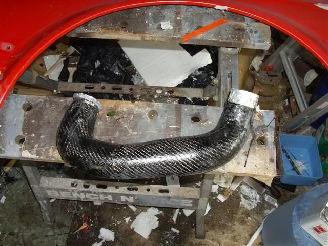
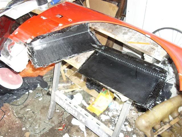
Have started making the mould for a front wing, have finished off a CF charge pipe, and started to stick the charge cooler together today
Have started making the mould for a front wing, have finished off a CF charge pipe, and started to stick the charge cooler together today
-
Turbo-Brown
- Boost Junkie
- Posts: 4705
- Joined: Tue Feb 15, 2005 11:00 pm
- Location: Aldershot, Hants
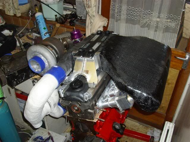
Bit of a random bitsa update
The last bit of charge pipe is pretty much finished save for cleaning the excess resin off the V-band end of it
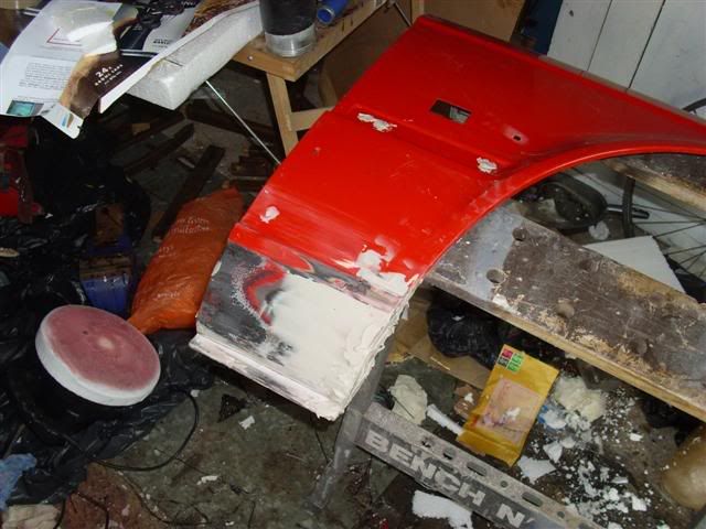
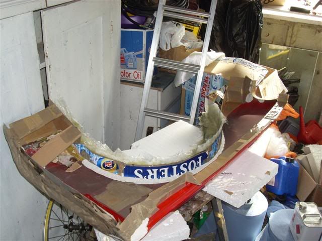
I've started to repair one of the wings in preparation for mould making
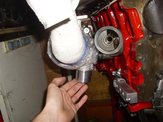
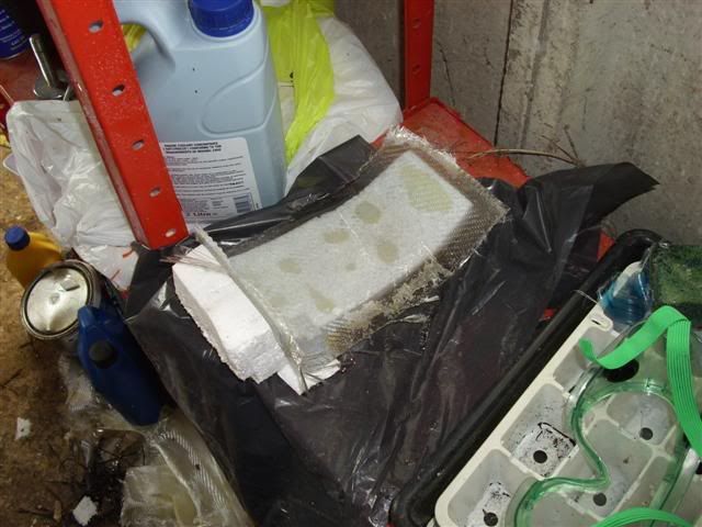
Cleared the foam out of the inlet side of the charge cooler.
Think this really needs a turning vane inside it so help prevent all the air from rushing up to the far end so made another foam buck:
Couldn't be bothered to PVA it this time as it only has a simple curvature to it, so I glued a sheet of that transparent thin plastic packaging stuff onto it. It's rigid enough to support the curing laminate anyway, and it peels off the back easily too
So there's the curing turning vane. Once it's cured, I'll peek the buck off and then trim it to suit the inside of the inlet before bonding the vane in. It's just made of woven glass this time incidentally
The vane should also help prevent the top and bottom surfaces of the inlet from bowing out under pressure.
Finally, decided that the airbox side of the cooler really needs to be removable as the whole assembled cooler will be quite unweildy, so to that end I made up a couple of CF sheets with a 90degree bend in them:
These will be bonded top and bottom to the core and inlet, and have a metal strip bonded to them so that the airbox can be bolted on and is easy to remove
The last bit of charge pipe is pretty much finished save for cleaning the excess resin off the V-band end of it
I've started to repair one of the wings in preparation for mould making
Cleared the foam out of the inlet side of the charge cooler.
Think this really needs a turning vane inside it so help prevent all the air from rushing up to the far end so made another foam buck:
Couldn't be bothered to PVA it this time as it only has a simple curvature to it, so I glued a sheet of that transparent thin plastic packaging stuff onto it. It's rigid enough to support the curing laminate anyway, and it peels off the back easily too
So there's the curing turning vane. Once it's cured, I'll peek the buck off and then trim it to suit the inside of the inlet before bonding the vane in. It's just made of woven glass this time incidentally
The vane should also help prevent the top and bottom surfaces of the inlet from bowing out under pressure.
Finally, decided that the airbox side of the cooler really needs to be removable as the whole assembled cooler will be quite unweildy, so to that end I made up a couple of CF sheets with a 90degree bend in them:
These will be bonded top and bottom to the core and inlet, and have a metal strip bonded to them so that the airbox can be bolted on and is easy to remove
-
m_jermyn
- E30 Zone Team Member
- Posts: 4208
- Joined: Sat Mar 14, 2009 11:00 pm
- Location: Sydney Australia Mate
The carbon master.... Boy I wish I could do that.. How did you learn?
-
Turbo-Brown
- Boost Junkie
- Posts: 4705
- Joined: Tue Feb 15, 2005 11:00 pm
- Location: Aldershot, Hants
Just from a book really, and lots of trial and error I'm still getting to grips with what you can and can't get the cloth to do. Like I got it wrong with that bit of pipe and ended up just wrapping it with 6" squares of overlapping CF.
-
ShakeyC
- E30 Zone Regular
- Posts: 785
- Joined: Sun Apr 29, 2007 11:00 pm
Doing very well so far although spent most of today reading it, can i make out a couple of points for others who may dabble with composites im sure you already know Turbo-Brown.
1. When laying up you have fair amount of working time so don't rush sticking it all down straight away.
2. With carbon fibre i found after 10-15mins the epoxy resin stuff starts to get really tacky and if you pull carbon fibre up because of mistake/bubbles you screw up the weave pattern, better to dab a brush onto it than to try peel it off to make corrections.
3. CF and heat is fine but epoxy resin is not so fine. In an engine bay the heat affects the resin it actually makes it harder BUT this makes it more brittle, a UV coat/agent mixed in helps raise the temperature it becomes brittle. Not end of the world but important to be aware of in engine bay.
-
Turbo-Brown
- Boost Junkie
- Posts: 4705
- Joined: Tue Feb 15, 2005 11:00 pm
- Location: Aldershot, Hants
Yes, there are some precautions you can take to increase the working time too, like pouring your mixed up batch of resin into a shallow tray and brushing it from there. It's quite annoying when a deep pot of resin gels and you have to mix stuff up again
It will happen though so you can reduce your stress levels if you have clean containers and brushes on stand by so that mixing another batch takes two minutes rather than fifteen.
I wasn't aware of the embrittlement of epoxy, think only one or two of my bits are epoxy now, the rest are polyester. Don't know if that's a good thing or not. I imagine that having black CF panels in the blazing summer sun causes similar problems too doesn't it?
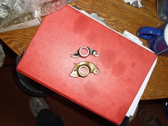
Little update, decided to buy a set of uprated rockers.
They're made from steel and cost a mighty £148 per set of 12, so the bank isn't too badly broken, and neither should the rockers Obviously they'll be a little heavier than standard, but at least I can rev to the heavens with peace of mind that they won't break.
It will happen though so you can reduce your stress levels if you have clean containers and brushes on stand by so that mixing another batch takes two minutes rather than fifteen.
I wasn't aware of the embrittlement of epoxy, think only one or two of my bits are epoxy now, the rest are polyester. Don't know if that's a good thing or not. I imagine that having black CF panels in the blazing summer sun causes similar problems too doesn't it?
Little update, decided to buy a set of uprated rockers.
They're made from steel and cost a mighty £148 per set of 12, so the bank isn't too badly broken, and neither should the rockers
-
e21Jason
- E30 Zone Addict
- Posts: 2040
- Joined: Tue Jan 11, 2005 11:00 pm
- Location: Dubai, UAE
Hi Alex
I would try to add a diffuser plate for the supply end of the core basicaly a perforated sheet of alloy to equilse the air velocity.
Also Mr Newmans rockers have the pads braised on so the tolerance varies a lot, if you find soem way out send them back.
Jason
I would try to add a diffuser plate for the supply end of the core basicaly a perforated sheet of alloy to equilse the air velocity.
Also Mr Newmans rockers have the pads braised on so the tolerance varies a lot, if you find soem way out send them back.
Jason
-
odbod
- E30 Zone Regular
- Posts: 298
- Joined: Mon May 08, 2006 11:00 pm
- Location: leamington Spa
It's not quite as simple as epoxy will get more brittle...
All epoxy's (and other plastics) have a Tg (Glass transition temperature) This is the temperature at which the epoxy goes through a phase change from a solid to a glassy type structure, at this point an epoxy will basically take no load and become rubbish, and as a consequecne so will your composite.
For under the bonnet I would go with a min. 120C Tg, better 160-200C. We use 195-215C Tg systems for F1 Pressure vessels and our other high temperature composites.
In terms of epoxy's becoming more brittle this is actually associated with the extent of cure, if you have a resin that is say 70-80% cured it will be relatively tough but it's Tg will not be as high as it can be, if you then heat cycle that component the extent of cure will go up to say 90-95% and the Tg rises but the impact resistance will reduce, so if you use a high Tg system in the first place this is less of an issue.
If you repeatedly take an epoxy resin above it's Tg then it's performance will degrade. Any system that goes off at room temp/50-60 degrees is likely to be a sub 100c Tg and may (note the word may) lead to issues later on. Anything that needs 160C to post cure is likely to be OK, but best to check the manufacturers data sheet.
It all depends on where you are putting it, around the intercooler or intake away from high temps will be fine, anything bolted to the engine that could get to 80-90+ degrees may casue a headache longer term.
That said, awesome build

-
Turbo-Brown
- Boost Junkie
- Posts: 4705
- Joined: Tue Feb 15, 2005 11:00 pm
- Location: Aldershot, Hants
Ooh, that's a bit of a worry for the inlet of the charge cooler as it's close to the exhaust housing of the big turbo.
Will have to make up some decent heat shielding for that!
Anyway, will have to wait and see what causes problems
Cheers for the heads up on the rockers Jason, will give them all a good measure when they arrive! Guess I could drill the turning vane to get some kind of balance both sides. It all spills out into the same chamber though so it shouldn't be too much of an issue I don't think.
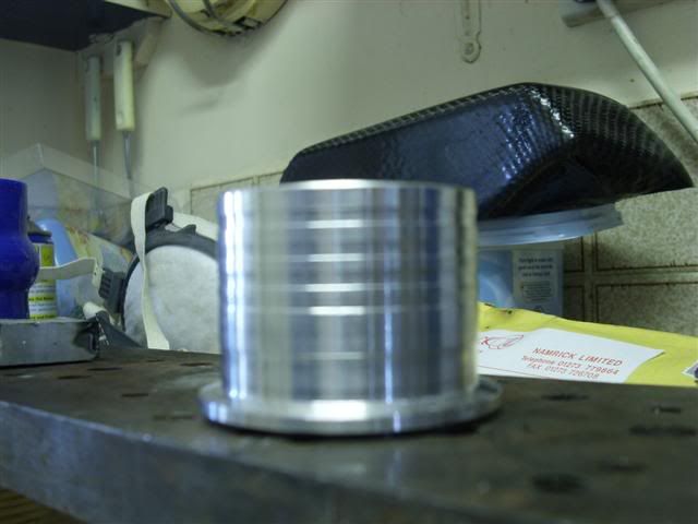
Have spent all my time this weekend making a simple bloody v-band clamp! Couldn't find anywhere which sold them in the right size unfortunately, so here's the end resultL
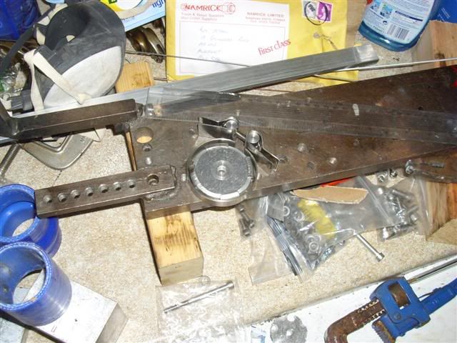
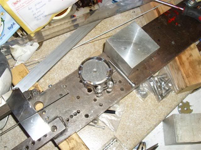
It's little steps I know, but all these things need making before I can sort out homes for the actuators and that kind of thing.
Also, filled in the spec sheet for my dry sump pump. Spent ages trying to find out on the internet how fast the standard pump is driven relative to crank speed.....and then it suddenly occurred to me that it must be half crank speed as the dizzy drive used to be taken from the same point. How stupid do I feel?!
Will have to make up some decent heat shielding for that!
Anyway, will have to wait and see what causes problems
Cheers for the heads up on the rockers Jason, will give them all a good measure when they arrive! Guess I could drill the turning vane to get some kind of balance both sides. It all spills out into the same chamber though so it shouldn't be too much of an issue I don't think.
Have spent all my time this weekend making a simple bloody v-band clamp! Couldn't find anywhere which sold them in the right size unfortunately, so here's the end resultL
It's little steps I know, but all these things need making before I can sort out homes for the actuators and that kind of thing.
Also, filled in the spec sheet for my dry sump pump. Spent ages trying to find out on the internet how fast the standard pump is driven relative to crank speed.....and then it suddenly occurred to me that it must be half crank speed as the dizzy drive used to be taken from the same point. How stupid do I feel?!
-
ShakeyC
- E30 Zone Regular
- Posts: 785
- Joined: Sun Apr 29, 2007 11:00 pm
You should be ok as its on the cold side, i was just saying in simpleton terms for everyone else's benefit.
-
Turbo-Brown
- Boost Junkie
- Posts: 4705
- Joined: Tue Feb 15, 2005 11:00 pm
- Location: Aldershot, Hants
Fingers very much crossed! Was planning to vent the bonnet above the turbos so creating a partition to the charge cooler shouldn't be too difficult and it should fight against heat soak too.....with any luck
Hooray! After a two week wait, we have rockers!
They're about twice the weight of the ali ones but the mass is very much concentrated around the central boss so hopefully they shouldn't have a massively different radius of gyration to the standard ones.
Can finally get on and build the 'head now
Just out of interest, can anyone tell me what you're supposed to coat the MLS head gaskets with?
-
Turbo-Brown
- Boost Junkie
- Posts: 4705
- Joined: Tue Feb 15, 2005 11:00 pm
- Location: Aldershot, Hants
Litte bit of a mixed bag today, was going to install the rockers and new cam in the 'head....or so went the plan
I'd forgotten that when I put my last set of ITBs on, I tried to remove the long manifold stud and succeeded in breaking it off. I'd tried to drill it out last time too, but gave up.
This wasn't too much of a problem as the old ITBs had a 25mm thick plate which bolted to the head meaning you could get away without one bolt, but this time round they're only 8mm thick so
I wondered if weighing the head down would be enough to stop it moving whilst I drill out the old stud, but it's not Think I'll make up a strap which can be bolted to the head and mill to prevent it all moving about.
Secondly, I spotted something which has got me worrying!
Here's the new pistons and the like at TDC:
I'm worried that they're not supposed to poke up above the deck of the block like that! Anyone know for sure?
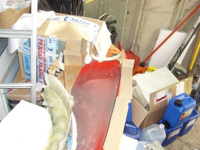
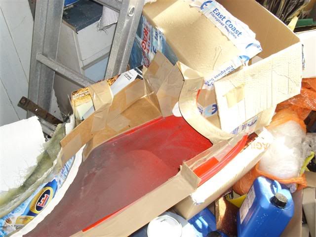
Anyway, after failing to get much done at the parents' house, I went home and cracked on with making the mould for a front wing.
The wheelarch portion of the mould is removable which will hopefully make it easier to get the finished panel out:
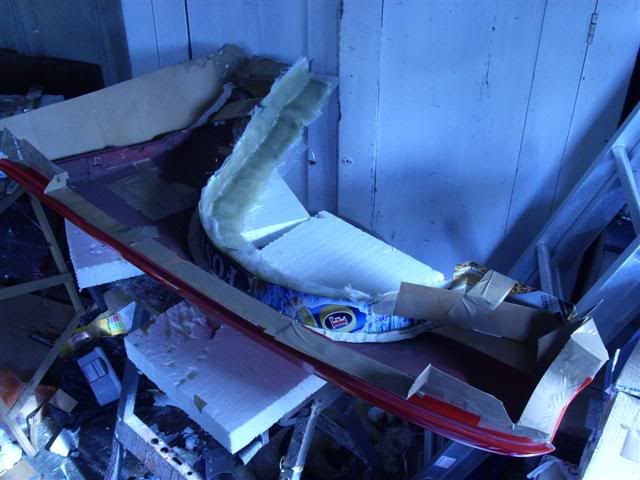
And the rest of the panel is all hemmed in, again to give some margins to laminate on to and make removing the finished article easier
I'd forgotten that when I put my last set of ITBs on, I tried to remove the long manifold stud and succeeded in breaking it off. I'd tried to drill it out last time too, but gave up.
This wasn't too much of a problem as the old ITBs had a 25mm thick plate which bolted to the head meaning you could get away without one bolt, but this time round they're only 8mm thick so
I wondered if weighing the head down would be enough to stop it moving whilst I drill out the old stud, but it's not
Secondly, I spotted something which has got me worrying!
Here's the new pistons and the like at TDC:
I'm worried that they're not supposed to poke up above the deck of the block like that! Anyone know for sure?
Anyway, after failing to get much done at the parents' house, I went home and cracked on with making the mould for a front wing.
The wheelarch portion of the mould is removable which will hopefully make it easier to get the finished panel out:
And the rest of the panel is all hemmed in, again to give some margins to laminate on to and make removing the finished article easier
-
Gunni
- E30 Zone Addict
- Posts: 2115
- Joined: Tue Jan 11, 2005 11:00 pm
- Location: Oxford
The pistons are NOT supposed to peak over the deck that much.
They standard sit flush with the deck on the rim.
Is that a whole mm it´s poking over?
Is not going to be a problem if you where to run a MLS gasket of .12 or larger
Are these lower compression pistons as well?
They standard sit flush with the deck on the rim.
Is that a whole mm it´s poking over?
Is not going to be a problem if you where to run a MLS gasket of .12 or larger
Are these lower compression pistons as well?
-
Turbo-Brown
- Boost Junkie
- Posts: 4705
- Joined: Tue Feb 15, 2005 11:00 pm
- Location: Aldershot, Hants
They are lower compression pistons, I'm beginning to wonder if the B20 block is shorter than the B25 one now!
I measured the pistons when they came and the gudgeon pin is 4.5mm higher than standard, so they should fit!
Do have an MLS gasket of stock thickness, will have to have a measure...a hope and a pray!
I measured the pistons when they came and the gudgeon pin is 4.5mm higher than standard, so they should fit!
Do have an MLS gasket of stock thickness, will have to have a measure...a hope and a pray!
-
UweM3
- E30 Zone Squatter
- Posts: 1657
- Joined: Sun Jul 03, 2005 11:00 pm
the stock pistons on the S14 engine stick out 0.7mm
-
Turbo-Brown
- Boost Junkie
- Posts: 4705
- Joined: Tue Feb 15, 2005 11:00 pm
- Location: Aldershot, Hants
Aah that's interesting, I reckon it should be 0.7mm on the M20 too.
I've got a stock M20 at my parents' house with the 'head off so I can measure up at the weekend and see whether something's wrong
I've got a stock M20 at my parents' house with the 'head off so I can measure up at the weekend and see whether something's wrong