
Twin Seq. Dry sumping for beginners :D
Moderator: martauto
-
Scoupe

- E30 Zone Newbie

- Posts: 95
- Joined: Fri Jan 26, 2007 11:00 pm
oh right, so its the little flap in the exhaust that he wants controlled?
-
Turbo-Brown
- Boost Junkie
- Posts: 4705
- Joined: Tue Feb 15, 2005 11:00 pm
- Location: Aldershot, Hants
It's a great big flap in the air system which I need to get to move at the moment.
The input needs to be based on pressure and the output just a PWM signal whose PW increases with increasing pressure.
Not found the voltages which the MAP sensor gives out yet, need to do that pretty soon by the sounds of it from you and JK!
Guess if I rig it up to a 5v supply and a pressure gauge and list out what effect varying pressures have on the voltage output or something to that effect?
Now where did I put that power supply?!
-
Scoupe
- E30 Zone Newbie
- Posts: 95
- Joined: Fri Jan 26, 2007 11:00 pm
Yeah that would be ideal. Depends (loosely) on the type of thing that you use.
What does this flap do then control exhaust/inlet gas flow between the two turbos?
And what sort of device are you planning to use to move it?
What does this flap do then control exhaust/inlet gas flow between the two turbos?
And what sort of device are you planning to use to move it?
-
Turbo-Brown
- Boost Junkie
- Posts: 4705
- Joined: Tue Feb 15, 2005 11:00 pm
- Location: Aldershot, Hants
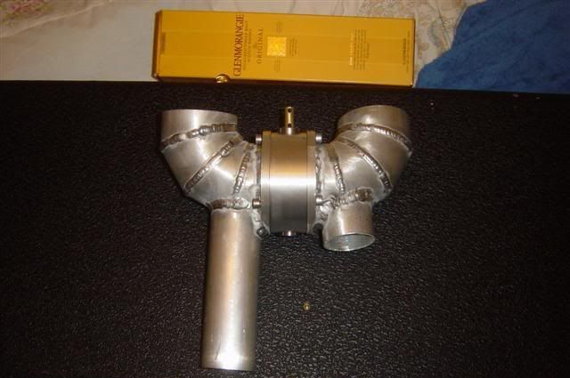
The flap controls which turbo's compressed air gets to the engine and will live in the gap between these two ali elbows:
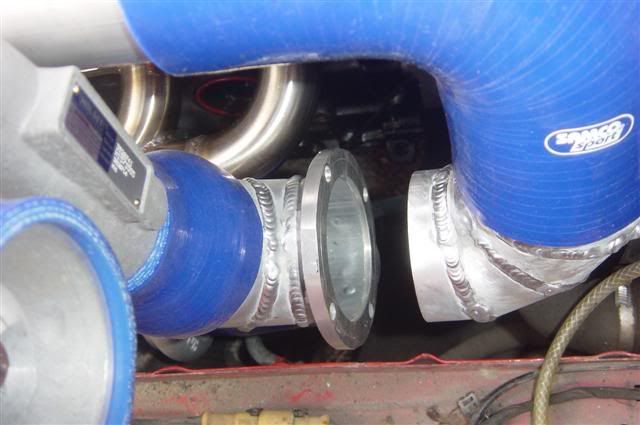
To move the flap, there will be a piston-in-cylinder kind of actuator which is supplied with a constant vacuum source from an engine driven pump. The movement of the actuator is then governed by a 3-port solenoid valve.
To move the flap, there will be a piston-in-cylinder kind of actuator which is supplied with a constant vacuum source from an engine driven pump. The movement of the actuator is then governed by a 3-port solenoid valve.
-
jkarran
- E30 Zone Regular

- Posts: 327
- Joined: Thu Jan 12, 2006 11:00 pm
- Location: Isle of Man
That'll do nicely.Turbo-Brown wrote:Guess if I rig it up to a 5v supply and a pressure gauge and list out what effect varying pressures have on the voltage output or something to that effect?
Now where did I put that power supply?!
jk
E30 320i Rally Turd - Usually broken
E24 635Csi - Rotting in peace for now
E34 540i - Daily driver
Blown R1 Striker - In progress
E24 635Csi - Rotting in peace for now
E34 540i - Daily driver
Blown R1 Striker - In progress
-
Turbo-Brown
- Boost Junkie
- Posts: 4705
- Joined: Tue Feb 15, 2005 11:00 pm
- Location: Aldershot, Hants
Made a guitar amp for a GCSE project which had a nice mains powered adjustable power supply in it, I know I've still got the thing somewhere.......but WHERE OH WHERE IS IT?!
Gotta do some work for someone this weekend anyway so progress will have to come to a temporary halt.
Probably a bit late to order exhaust components in time for Christmas now too I imagine.
Worked out I need about £400 worth of pipe and bends etc to make the twin 3" and 2" system and silencer (although that does include £70 to make a straight through back-box for the E32 too
  )
)
Gotta do some work for someone this weekend anyway so progress will have to come to a temporary halt.
Probably a bit late to order exhaust components in time for Christmas now too I imagine.
Worked out I need about £400 worth of pipe and bends etc to make the twin 3" and 2" system and silencer
-
Scoupe
- E30 Zone Newbie
- Posts: 95
- Joined: Fri Jan 26, 2007 11:00 pm
Ouch, but I suppose if its in the name of going fast then its worth it!
-
Speedtouch
- Old Skooler

- Posts: 14099
- Joined: Tue Feb 14, 2006 11:00 pm
- Location: Canterbury
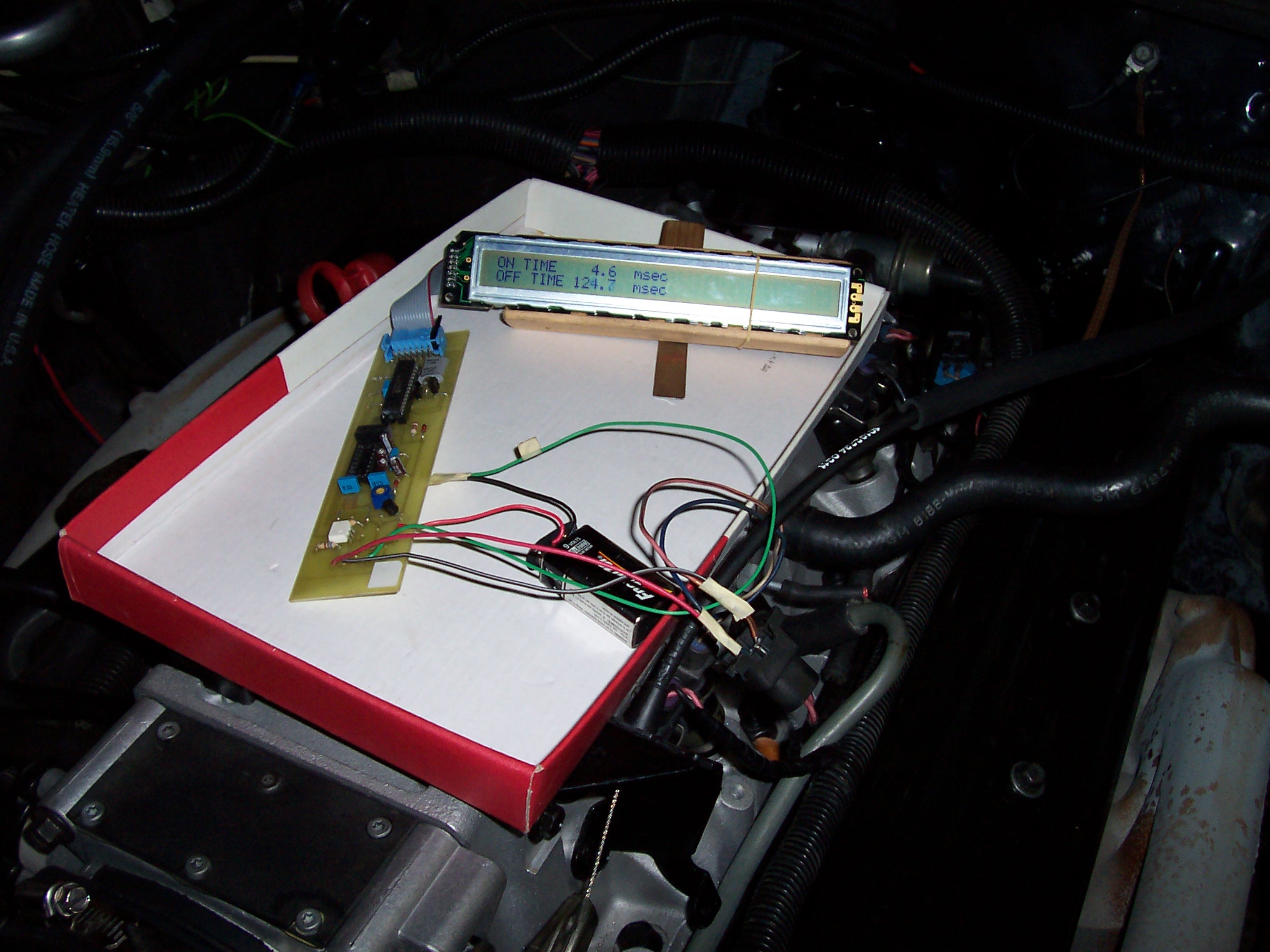
Thought this might be of interest, to monitor your flappy thing...
http://www.diy-efi.org/diy_efi/projects/pw_meter1/
http://www.diy-efi.org/diy_efi/projects ... 0_0021.JPG
http://www.diy-efi.org/diy_efi/projects/pw_meter1/
http://www.diy-efi.org/diy_efi/projects ... 0_0021.JPG
///M aurice
ECU Upgrade EPROM Chips, £40 posted within the UK. Note these are not Zone chips.
viewtopic.php?f=6&t=279421
ECU Upgrade EPROM Chips, £40 posted within the UK. Note these are not Zone chips.
viewtopic.php?f=6&t=279421
-
Turbo-Brown
- Boost Junkie
- Posts: 4705
- Joined: Tue Feb 15, 2005 11:00 pm
- Location: Aldershot, Hants
Crikey, I read through PIC programs and recognise most of the commands, but really can't get my head around what the gumf after the basic command makes the thing do!
Think with the 555 based PWM circuit the ADV should be made to function adequately....or at least I hope it will!
Think with the 555 based PWM circuit the ADV should be made to function adequately....or at least I hope it will!
-
Turbo-Brown
- Boost Junkie
- Posts: 4705
- Joined: Tue Feb 15, 2005 11:00 pm
- Location: Aldershot, Hants
Hokey dokey!
Finished off (barring a couple of hose clips and things) Oakey's throttles so I'm free for a while to work on Pinky!
Here he is, resplendent in faded BrilliantRot paint You have to use your imagination, but he'll look alot better once he gets his carbon bonnet, front wings, sunroof, door skins and boot lid.....and the rest of the metal is painted black! Will also have my nice polished lip staggered offset wheels on too

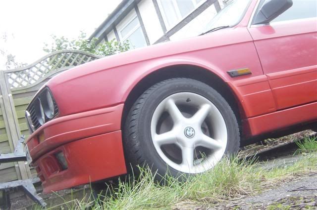

Might delete the side skirts etc. too, not sure yet.
Aren't those 5 spokes shockingly '90s too!
So, having finished all I could on the ITBs, I turned my attention to the mechanicals of the Air Divertor Valve.
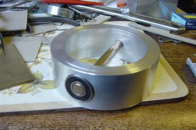
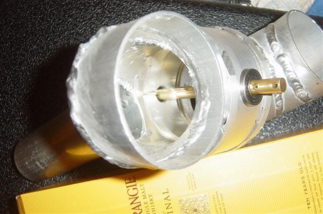
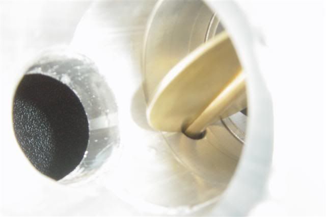
This is essentially just a large diameter (76.5mm) throttle body with a sealed ball race at each end and a brass spindle. The whole thing's about 35mm long so it's fairly compact. Just need to finish off the spindle and drill the body to accept the bolts which will hold the two elbows on
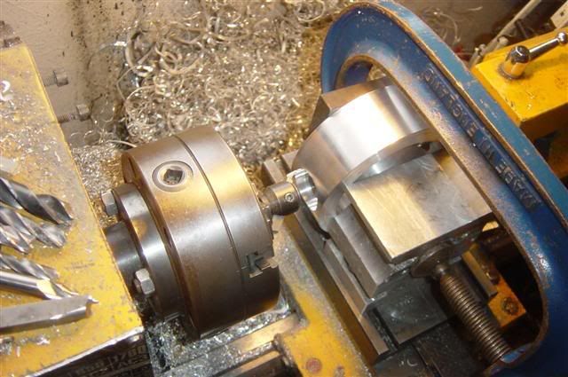
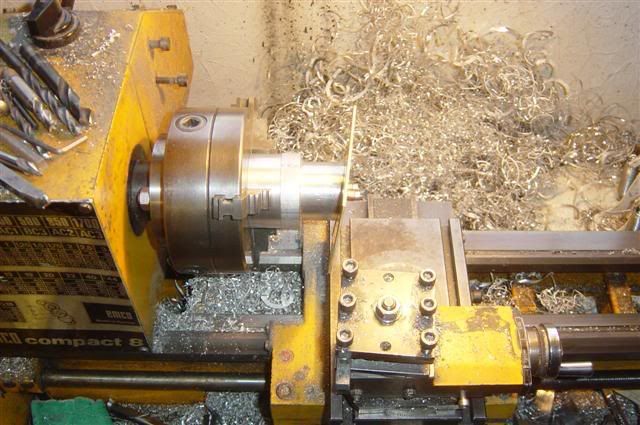
Here's the body being counterbored for a bearing. Like a twat I absent mindedly drilled all the way through in a previous operation so I need to make up a sleeve which increases the spindle diameter later on! The centre of the body has been machined out by this point:
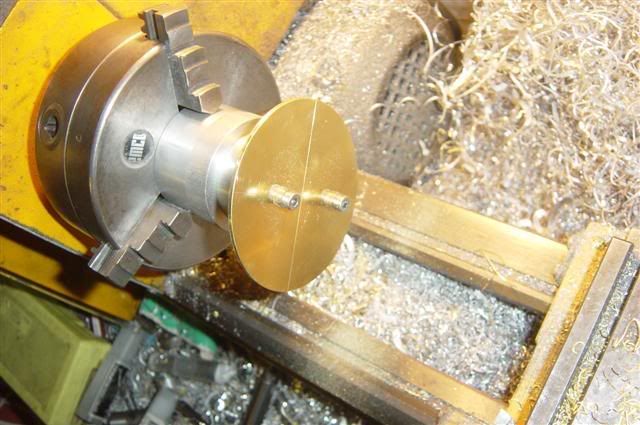
Here's the blank butterfly bolted to the attachment I use for making butterflies. The blank is just a square sheet of 2mm thick brass with a pair of holes drilled in it:
Here's the attachment and butterfly on the lathe ready to be machined down to size@
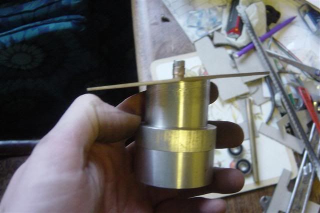
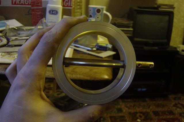
And after about half an hour, you end up with one of these:
Which goes in this assembly:
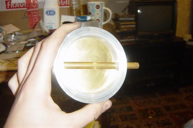
To give this:
Quite pleased to have got that far with the valve today actually! Will pop back tomorrow for a couple of hours and make a start on the actuators
Finished off (barring a couple of hose clips and things) Oakey's throttles so I'm free for a while to work on Pinky!
Here he is, resplendent in faded BrilliantRot paint
Might delete the side skirts etc. too, not sure yet.
Aren't those 5 spokes shockingly '90s too!
So, having finished all I could on the ITBs, I turned my attention to the mechanicals of the Air Divertor Valve.
This is essentially just a large diameter (76.5mm) throttle body with a sealed ball race at each end and a brass spindle. The whole thing's about 35mm long so it's fairly compact. Just need to finish off the spindle and drill the body to accept the bolts which will hold the two elbows on
Here's the body being counterbored for a bearing. Like a twat I absent mindedly drilled all the way through in a previous operation so I need to make up a sleeve which increases the spindle diameter later on! The centre of the body has been machined out by this point:
Here's the blank butterfly bolted to the attachment I use for making butterflies. The blank is just a square sheet of 2mm thick brass with a pair of holes drilled in it:
Here's the attachment and butterfly on the lathe ready to be machined down to size@
And after about half an hour, you end up with one of these:
Which goes in this assembly:
To give this:
Quite pleased to have got that far with the valve today actually! Will pop back tomorrow for a couple of hours and make a start on the actuators
-
Speedtouch
- Old Skooler
- Posts: 14099
- Joined: Tue Feb 14, 2006 11:00 pm
- Location: Canterbury
Nice work! Hope you used plenty of that E45 lotion afterwards  Was it all done at home?
///M aurice
ECU Upgrade EPROM Chips, £40 posted within the UK. Note these are not Zone chips.
viewtopic.php?f=6&t=279421
ECU Upgrade EPROM Chips, £40 posted within the UK. Note these are not Zone chips.
viewtopic.php?f=6&t=279421
-
Turbo-Brown
- Boost Junkie
- Posts: 4705
- Joined: Tue Feb 15, 2005 11:00 pm
- Location: Aldershot, Hants
Bah! Who needs silky skin?!
T'was indeed all done at home, well, my parent's home anyway. God bless them and their ability to put up with car parts littering the house
T'was indeed all done at home, well, my parent's home anyway. God bless them and their ability to put up with car parts littering the house
-
Turbo-Brown
- Boost Junkie
- Posts: 4705
- Joined: Tue Feb 15, 2005 11:00 pm
- Location: Aldershot, Hants
Not got all that much done today unfortunately, but hey; it's new years eve....time for booooze!
Just a couple of pics of the ADV assembly, only managed to drill and tap the holes in the valve body which hold the elbows on, and also bore out the part of the elbow with the short stub so that air can get to the inlet of the small turbo
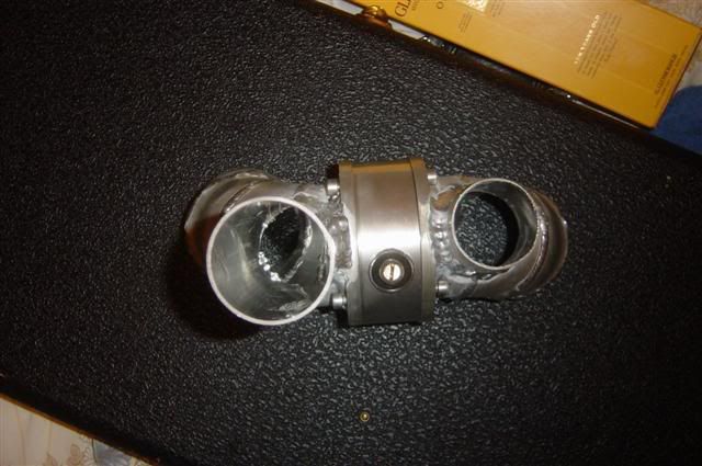
Just need to go through smoothing off all the welds inside and smooth the transitions between the elbows and the valve body and that's done!
Happy New Year everybody!
Just a couple of pics of the ADV assembly, only managed to drill and tap the holes in the valve body which hold the elbows on, and also bore out the part of the elbow with the short stub so that air can get to the inlet of the small turbo
Just need to go through smoothing off all the welds inside and smooth the transitions between the elbows and the valve body and that's done!
Happy New Year everybody!
-
Ant
- Retired Team Member
- Posts: 10496
- Joined: Tue Dec 21, 2004 11:00 pm
- Location: PD+E dept :D
^ Uber Alex !!!
Product Development and Endurance for Delphi.
Original performance chips, original works not unlicensed copies Email FTW
Original performance chips, original works not unlicensed copies
-
Turbo-Brown
- Boost Junkie
- Posts: 4705
- Joined: Tue Feb 15, 2005 11:00 pm
- Location: Aldershot, Hants
Today's update is that I've moved the pink car off the drive and onto the grass, and put poor old Brown on the drive ready to disassemble.
First thing to come off it was the ECU which will be sent off for an upgrade next week hopefully, upgrade consists of lots of little odds and sods but most importantly......SELF MAPPING!!!!
-
Turbo-Brown
- Boost Junkie
- Posts: 4705
- Joined: Tue Feb 15, 2005 11:00 pm
- Location: Aldershot, Hants
:sharp intake of breath: the pistons are on order!
Should have a crank and some conrods soon too!
Should have a crank and some conrods soon too!
-
Gunni
- E30 Zone Addict

- Posts: 2115
- Joined: Tue Jan 11, 2005 11:00 pm
- Location: Oxford
Self mapping?
-
Turbo-Brown
- Boost Junkie
- Posts: 4705
- Joined: Tue Feb 15, 2005 11:00 pm
- Location: Aldershot, Hants
It can trim the ignition dependant on EGTs, and has a target AFR table to help with the fuel mapping. It also has boost dependant AFR trims.
Will still be taking it to Emerald to be properly mapped, but it should help out massively when I'm getting up and running!
Will still be taking it to Emerald to be properly mapped, but it should help out massively when I'm getting up and running!
-
JazzMan
- E30 Zone Camper

- Posts: 1070
- Joined: Sat Mar 26, 2005 11:00 pm
- Location: Deep South
In awe of your mechanical skill looks like a work of art

-
Speedtouch
- Old Skooler
- Posts: 14099
- Joined: Tue Feb 14, 2006 11:00 pm
- Location: Canterbury
How did you get the roller bearings mounted on the butterfly spindle - interference fit, or by heating up the alloy housing and 'shrinking' them in?
///M aurice
ECU Upgrade EPROM Chips, £40 posted within the UK. Note these are not Zone chips.
viewtopic.php?f=6&t=279421
ECU Upgrade EPROM Chips, £40 posted within the UK. Note these are not Zone chips.
viewtopic.php?f=6&t=279421
-
oakey
- E30 Zone Addict
- Posts: 4891
- Joined: Fri Feb 10, 2006 11:00 pm
- Location: Surrey
Alex. Where are you getting your carbon body panels?

-
Gunni
- E30 Zone Addict
- Posts: 2115
- Joined: Tue Jan 11, 2005 11:00 pm
- Location: Oxford
remember EGT isn´t instantious. So I think Ignition can´t be tuned automatically in a car unless on a dyno through logging by the engine management.Turbo-Brown wrote:It can trim the ignition dependant on EGTs, and has a target AFR table to help with the fuel mapping. It also has boost dependant AFR trims.
Will still be taking it to Emerald to be properly mapped, but it should help out massively when I'm getting up and running!
-
Turbo-Brown
- Boost Junkie
- Posts: 4705
- Joined: Tue Feb 15, 2005 11:00 pm
- Location: Aldershot, Hants
Cheers Jazzman, you're very kind! Doesn't look quite so spanky in the metal though
I'm just gluing the bearings into the alloy valve body, and then making a little deformation on the spindle so it's a light press fit.
Hey Dave, I'm getting them from my garage Just too darned expensive to buy them in so I'm going to make them.
You're quite right Gunni, but it can knock the ignition back if the EGTs get too high and keep the value the same after that. For the most part though, the self mapping is down to the fueling side of things.
I'll probably load up the ignition map I had in Brown, richen up Brown's fuel map and then let the ECU work the fueling back from there.
I'm just gluing the bearings into the alloy valve body, and then making a little deformation on the spindle so it's a light press fit.
Hey Dave, I'm getting them from my garage
You're quite right Gunni, but it can knock the ignition back if the EGTs get too high and keep the value the same after that. For the most part though, the self mapping is down to the fueling side of things.
I'll probably load up the ignition map I had in Brown, richen up Brown's fuel map and then let the ECU work the fueling back from there.
-
Gunni
- E30 Zone Addict
- Posts: 2115
- Joined: Tue Jan 11, 2005 11:00 pm
- Location: Oxford
EGT measuring using known max numbers at specific load and rpm is definitely a good thing to have.
As EGT shouldn´t go higher after mapping, but will in a longer pull or up a hill for instance,
but then again, it´s going to be very powerfull anyway
As EGT shouldn´t go higher after mapping, but will in a longer pull or up a hill for instance,
but then again, it´s going to be very powerfull anyway
-
Turbo-Brown
- Boost Junkie
- Posts: 4705
- Joined: Tue Feb 15, 2005 11:00 pm
- Location: Aldershot, Hants
Don't really have too many reeeeeally long hills around here, and unless I take it to a track/strip it's never going above 70 anyway so I shouln't be holding full load for more than 5s at a time I wouldn't think.
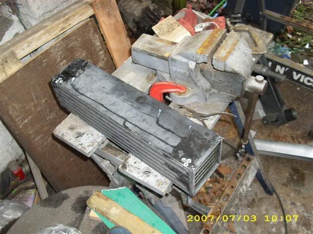
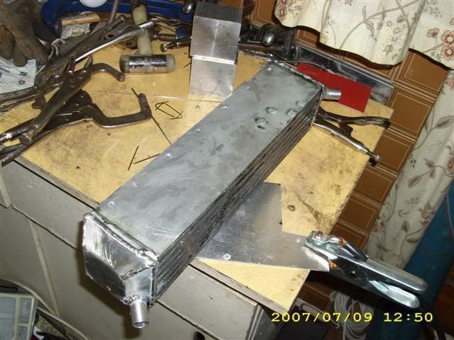
Done a little bit more on the charge cooler today (started taking Brown apart yesterday but the weather's been poo today).
Tested another IC core for leaks after the last one turned out to have had a hole drilled in it from the factory. This one was fine though so I set about removing the rivets from it (don't want the engine swallowing one!).
Used our trusty band saw to remove the end tanks this time so the cuts are really nice and neat:

Then bought some Nitromors to get the paint off. God only knows what paint's been used as it's taking an age to bubble up! I've left the whole thing caked in stripper and wrapped in a bin bag so hopefully it'll be done by next weekend. Here's the new core anyway:
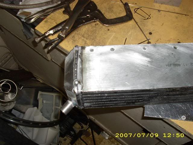
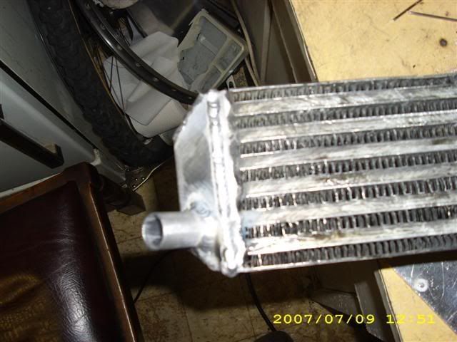
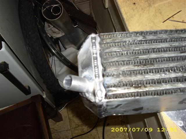
And to pass the time while the paint was un-drying, I welded the water connections on to the end tanks. Found a bit of 3/4" ali tube kicking about a little while ago, it's been SO handy for making hose connections! Gonna have to get some more I think!


Done a little bit more on the charge cooler today (started taking Brown apart yesterday but the weather's been poo today).
Tested another IC core for leaks after the last one turned out to have had a hole drilled in it from the factory. This one was fine though so I set about removing the rivets from it (don't want the engine swallowing one!).
Used our trusty band saw to remove the end tanks this time so the cuts are really nice and neat:
Then bought some Nitromors to get the paint off. God only knows what paint's been used as it's taking an age to bubble up! I've left the whole thing caked in stripper and wrapped in a bin bag so hopefully it'll be done by next weekend. Here's the new core anyway:
And to pass the time while the paint was un-drying, I welded the water connections on to the end tanks. Found a bit of 3/4" ali tube kicking about a little while ago, it's been SO handy for making hose connections! Gonna have to get some more I think!
-
Turbo-Brown
- Boost Junkie
- Posts: 4705
- Joined: Tue Feb 15, 2005 11:00 pm
- Location: Aldershot, Hants
Ooh, got the ECU back yesterday! (less than a week it took! )
Good greif there are a bewildering array of functions to play with now!
Liking the sound of traction control though, it can (I think) compare the speed of the rear wheels to that of the front wheels and I believe you can tell it how much slip to allow before it intervenes. Think that'll be quite important for getting off the line, especially in the wet!
-
hoshy
- E30 Zone Wiki Guru
- Posts: 4118
- Joined: Tue Jan 18, 2005 11:00 pm
- Location: Munich
Hey Alex,
That's the upgraded Emerald yes?
do you know anything about what sensors it uses for the traction control? does it take 4 inputs?
That's the upgraded Emerald yes?
do you know anything about what sensors it uses for the traction control? does it take 4 inputs?
E46 M3 CSL but dreaming of another E30.
-
Jon_Bmw
- Dangerous when thinking
- Posts: 7606
- Joined: Tue Jan 11, 2005 11:00 pm
- Location: Salisbury
It will use the abs sensors I should think. Alex have you an LSD? The reason I ask is that the e30 abs is only 3 channel. Independant front but combined rear. I think with an LSD it will work better as it will 'lock' the wheels together, with an open, the slightest spin of the inside wheel and the traction control will be working overtime.
-
1an
- E30 Zone Addict
- Posts: 2384
- Joined: Sat Oct 28, 2006 11:00 pm
- Location: benfleet, essex
Alex cant you map it revs over time i think,
was chatting to Ant abbout traction control on megasquirt, run 2 maps kinda thing one with all the gadgets on it and one with nothing if that makes sense.
was chatting to Ant abbout traction control on megasquirt, run 2 maps kinda thing one with all the gadgets on it and one with nothing if that makes sense.

Audi S3 and Racing Puma track car.
-
Turbo-Brown
- Boost Junkie
- Posts: 4705
- Joined: Tue Feb 15, 2005 11:00 pm
- Location: Aldershot, Hants
You can use any digital or inductive sensor I believe, so you could fit a couple of sensors and have them looking at the bolt heads on the driveshafts where they attach to the diff for example, and just tell the ECU that 6 pulses=one revolution
Don't have to worry about interfering with the ABS system electronics or routing wires down the trailing arms then either
I've not decided on the diff yet Jon, I'm half tempted to get a Quaife but we'll see closer to the time. Might just take the easy option and get a beemer plate type diff, although it'd probably need a rebuild....Hmmmmm.
You mean like a set acceleration rate for the engine 1an? Must admit I've not looked all that far into it, but think that's more of a launch control thing than traction control. In theory I should be able to benefit from the TCS around corners aswell as off the line, although whether the boost cut will be able to work remains to be seen as I'm using two tables in the ECU to control the boost functions and only one of those tables is dedicated to boost.
-
1an
- E30 Zone Addict
- Posts: 2384
- Joined: Sat Oct 28, 2006 11:00 pm
- Location: benfleet, essex
Mr brown, surely a luanch control system is going to work the same as traction control to a degree. i was just talking to Ant about it and he said easyest way on MS is to do revs over time. so if the wheels spin the ecu will cut power until the revs raise at the time they have been mapped at i believe. dont hold me to it.
Audi S3 and Racing Puma track car.
-
Turbo-Brown
- Boost Junkie
- Posts: 4705
- Joined: Tue Feb 15, 2005 11:00 pm
- Location: Aldershot, Hants
I Think that would work well for launch control as you can see how quickly the vehicle is able to accelerate and then get the revs to rise at the same rate (for a given gear)
However, from a rolling start or flicking the car into a corner, you need to know how fast the car is going (average speed of the front wheels) and whether or not the back wheels are going significantly faster.
There are instances on every down change where you don't want the rate of acceleration of the engine to be capped as you rev-match.
-
1an
- E30 Zone Addict
- Posts: 2384
- Joined: Sat Oct 28, 2006 11:00 pm
- Location: benfleet, essex
yeah understand what your saying, its something i want to look into when i have MS put onto my car with the m50, apparently it takes quite a while to map it in but is well worth it for some hardcore driving.
Audi S3 and Racing Puma track car.
-
Turbo-Brown
- Boost Junkie
- Posts: 4705
- Joined: Tue Feb 15, 2005 11:00 pm
- Location: Aldershot, Hants
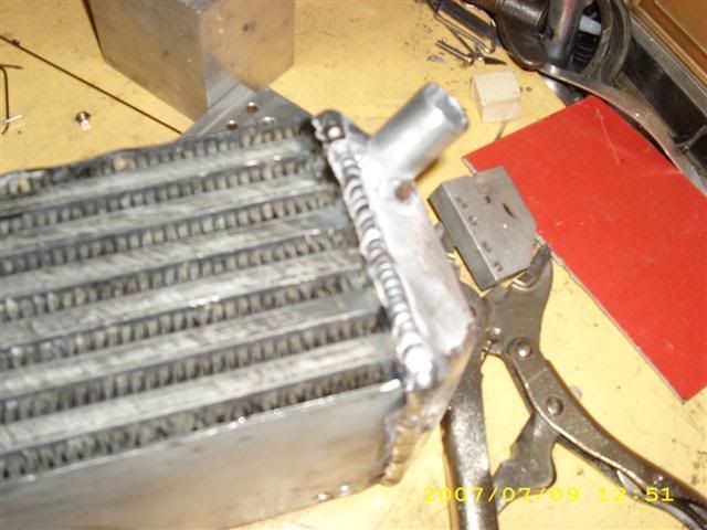
Well, I gave up on stripping the paint after another couple of attempts today and took instead to sanding the rest off.
Then had a go at filing the existing welds down to get the paint off them too.
Lastly thought I might as well try welding an end tank on and see what happens. I've never tried cast ali before and I've seen people say it's more difficult than stock ali but it welded up just fine!
The paint made the whole house stink though
Also got the new crank and rods today (many thanks indeed to DJC from the e36coupe site for delivering them!)
Shouldn't be too long until I can make a start on the remainder of the charge air plumbing and the charge cooler water system and, once those two bits (plus the exhaust) are taken care of I can haul the engine out and start the rebuild to 2.9litres
-
oldroydsr4
- E30 Zone Squatter

- Posts: 1579
- Joined: Tue Oct 25, 2005 11:00 pm
- Location: Warwick
There will be no need for tracktion control with an M50 unless you can't drive,
However a 450bhp twin turbo and it may well be required.
However a 450bhp twin turbo and it may well be required.