E30 from Ukraine - "Shadow of Intelligence"

Doing a minor build / restoration or an epic one, post it here

Moderator: martauto

User avatar
The_Glory
E30 Zone Regular
E30 Zone Regular
Posts: 381
Joined: Sun Feb 01, 2015 11:00 pm
Location: Kyiv, Ukraine

Thu Oct 06, 2022 11:45 am

Assembly_24. ЕТК_35_Clutch

To finish with the pedals, you need to install the clutch master cylinder on them. Let's go to the corresponding section of ETK.
Clutch

Its first subdivision.
Clutch
Image

Although it was a long time ago, I already changed the clutch disc and release bearing. I had no complaints about the clutch, so I don't plan to climb there again. I'm not even going to unscrew the gearbox from the engine. Therefore, we skip this section. If I do climb there, I will write about it later.

The second subdivision.
Clutch control drive
Image

Details #6, 11, 20-24 are not used. Parts #20-24 are used only on right-hand drive cars.

Clutch drive details.
Image

Bolts and nuts are galvanized with "yellow zinc".
All other parts are new. In the photo, only the hose is old - I really liked its blue color, after I washed it off the dirt - almost the color of the car :) But it turned out to be short, because the vacuum amplifier brake shifted forward, and a new hose had to be installed as well.
But, first I wanted to restore the original clutch master cylinder. Although it worked fine, I took it apart.
Image

Image

Cleaned, painted the body and installed a new repair kit Frenkit 419007.
Image

On the left are old original parts, on the right is a new repair kit.
Image

I found their numbers on the old original parts, maybe someone will need them.
Cuff
Image

Plynik
Image

Image

Hose insert
Image

FAG housing
Image

Everything is simple to assemble - remove the file, remove the retaining ring, pull out the stem and spring. Pull out the rod ring from the hinge, remove the cuffs. Assemble the parts from the repair kit in reverse order. I did all that and then bought a new cylinder :)
Image

I don't know why... it's just that I changed the clutch cylinder a long time ago, even after buying the car, so I decided it's better to change it for prevention. Well, together with the master cylinder as well, so that everything is already new, and you don't have to climb there anymore. Both cylinders were bought by ABS. Main ABS 51718X, working ABS 1800.
Image

Rubber inserts #3 and #9 in the motor shield are the same (21 52 1 156 082), but are no longer available for ordering. Although they were almost intact, I decided to replace them with new ones according to the replacement number (21 526 863 043) for E36 and other newer models. I somehow broke the plastic #7 (21 52 1 151 697) hose flange when removing the cylinder, so that's new as well.
Image

Old ones on the left, new ones on the right. The new inserts, in addition to the installation groove, have an additional "collar", which externally fits snugly to the sound insulation of the engine shield.
Image

Bracket No. 12 (34 34 1 163 565), similar to brake pipe brackets. I already wrote that only 10 of them are needed for the car. 2 pieces for the front brake pipes, 7 pieces for the rear brake pipes, and 1 piece for the clutch pipe.
The clutch tube is steel with a WP polymer coating, 260 mm long.

Now a small "live hack" that I found on the Internet. If you look carefully at the first general photo of the parts, you will not see a hose with a metal tube #19 (21 52 1 153 513). It is available to order, but at the price of 75 Euros - too much for me. I just cut my old hose off when I took it off so I wouldn't have to mess with it. If I had known its price then, maybe I would have fainted! :) Although, it would still have to be changed, it was cracked. So, we buy a regular rear brake hose (34 32 1 159 881), 200 mm long (I bought an ATE hose), and a WP steel brake pipe, 100 mm long.
Image

We connect them, and we get a similar hose, only 10 times cheaper.
Image

We compare it with the original hose - no difference. So why pay more? :)
Image

Now about the assembly. It would be more logical and easier to install the clutch master cylinder together with the hose, immediately on the pedal unit, and then install everything together on the car. But I did not do this, and now it was very inconvenient to screw it and insert the hose with a plastic flange. But he screwed it up.
Image

Image

Screw the cylinder rod to the pedal.
Image

The cylinder body and its hose exit through rubber inserts in the motor shield.
Image

Image

The outer rubber inserts tightly adhere to the noise insulation with their "collar" - much better than the old original ones.
Image

As I said, the old beautiful blue one :) the hose was now short and didn't reach the tank, so I put a new one.
Image

It remains to screw the tube to the cylinder. It was also not very convenient to do it, but I screwed it up.
Image

Next, we put a clamp and attach a "self-made" hose to the tube.
Image

The working cylinder of the clutch will lie on the shelf until the gearbox is installed. Then, on the spot, I will bend the tube of the "self-made" hose.
That's it with the pedals.
Next will be about the fuel system.
User avatar
The_Glory
E30 Zone Regular
E30 Zone Regular
Posts: 381
Joined: Sun Feb 01, 2015 11:00 pm
Location: Kyiv, Ukraine

Thu Oct 06, 2022 11:56 am

Assembly_25. ETK_16_Fuel supply system

The next step is the fuel system. It has long been in need of a fairly serious repair - the tank has been leaking at the joint for a long time and has already been several times, right on the road, sealed with "cold welding" (by the way, it holds up well), the pipes are very rusty, with "plumbing" from hoses, hoses with cracks, clamps are rusty, some parts were missing altogether. Therefore, the fuel system was almost completely replaced. To do this, I bought new original steel tubes, original clamps, all hoses, plastic tubes, fasteners, rubber neck and pump covers, clips and other small parts.
Image

Image

Image

Also found the tank, valve neck, metal and plastic shields in the rear right arch, plastic shields on the tank, tanks and fuel pump mounts in very good condition. Everything was cleaned, painted and galvanized.

So, the next big section of ETK - ETK_16_ Fuel supply system

We start again from the end of the chapter. There is such an interesting subdivision:

Fuel cooling system
Image

Judging by the ETC, this interesting option was only available for the Australian market - probably because it's very hot there ;) I've only seen this thing for sale once on ebay, in the same Australia. I didn't have time to buy, and delivery would be too expensive. But I kept the photo, because I will probably see something here live...
The photos are not mine - just for information about the rare E30 option.
Image

Judging from the photo, a special air conditioner hose with fuel pipes around it serves as a radiator. Therefore, it is logical that this option was placed only together with the air conditioner.

Image

Further, the tubes with the shield were somehow attached to the motor shield, perhaps instead of the usual shield.

Image

Then they went to the return fuel line.
This is such an interesting thing. Maybe someday I will buy it later! ;)

Well, now about my collection.
An external outboard fuel pump was installed on pre-restyling cars. It is located under the threshold, in front of the rear left wheel. There was also an option with two pumps - with an additional pumping pump in the tank. This is exactly the option on my car. Let's start with it.

Fuel pump
Image


Details of the outboard fuel pump.
Image

Pump No. 8 on the diagram (16 14 1 179 232) is used only in combination with a pumping pump. The original pump is BOSCH 0 580 464 070.
Image

I bought it new many years ago, and there are no complaints about its work until now. That's why I left him. But I have been interested in its fastening for a long time. I had it attached with a rubber ring #9 - like in this photo:
Image

But the ETK still has parts #10 (16 12 1 178 642), #11 (16 12 1 178 738), #12 (16 12 1 178 668), which I have never seen on an E30. I found their photo in Google.
Image
Image

These are rubber casings of the pump. I liked the look, so I ordered it, although I was not sure that they would fit, and the set costs more than $100. Fortunately, they approached. But, at the same time, rubber ring No. 9 becomes redundant. The pump is attached either through a ring or through these casings. They are not compatible together.
I was also interested in details #14 and #20. I understand that they are needed to reduce fuel pulsation from the pumps. I didn't have them at all. I can't say that it somehow negatively affected the operation of the fuel system, but I decided to assemble everything as it should have been from the factory. I found these tanks, and No. 14 is available in three versions.
Image

The first Wahler
Image

Second Bischoff
Image

The third Bosch
Image

The first and second are just empty tanks with a through passage. The third is under a rubber plug inside with some kind of membrane on the spring. But I don't know what was done with it, because there are traces of welding on it. Therefore, I chose the first option for installation.

I also want to pay attention to details No. 4 (16 12 1 177 892) and No. 5 (61 21 1 243 530). Only number 5 can be used. In most cases, they are broken, but the price of new original ones is inadequate, in my opinion. And there are no analogues for the number. I also had them torn, I was trying to think of something there, some kind of collective farm :) I was lucky to find a whole pump mount with all these parts. But I also found an alternative - after searching on Google "vibroisolator" I found this [URL='https://www.detal-if.com.ua/ru/bolt-bol ... -bbsh.html']this[/URL ] A great option for ridiculous money, compared to the original.

So, let's start the assembly.
All clamps were new original stainless steel. As practice has shown, even after 30 years, they spin up much better than the new Chinese ones.
Image

I made notes on the assembly for myself - the size, length of the hoses, and the size and number of clamps are indicated there. Maybe it will be useful to someone.
Image

We put the covers on the pump - they become very tight. We screw the tanks.
Image

Image

The terminals are now more protected by a casing.
Image

We screw the pump bracket to the body through vibration isolators and a hose clamp.
Image

By the way, in the section on plugs, I wrote that plugs are placed near the fuel pump in the doorway. I had these holes welded here when the fasteners for the pump were restored. But on the right side, these plugs remained under the antirust.
Image

Two plugs with a diameter of 20 mm (51 71 1 801 066) are required for each side.
Image

An outboard fuel pump is installed.
Image

Hose No. 18 with protective hose No. 19 is first installed on the tank, so we will talk about it later.
And as it turned out later, it is better to put the black tank #20 already after installing the tank, because it gets in the way a little, and it is not convenient to screw the hose #18 from the tank to it later. I had to remove it.

The next subdivision of ETK
Fuel line/ mounting elements
Image

At first I wanted to make custom copper fuel lines from a pattern from old pipes. But then I still decided to order ready-made original steel ones. It's good that they are already bent and fit perfectly, unlike the original brake pipes, which have to be bent in place yourself.
Image

Only three pipes - fuel supply (16 12 1 179 285), fuel return (16 12 1 177 372) and tank ventilation (16 13 1 177 466).
Image

Image

The diameter of all tubes is 8 mm, the length is specified in the ETK.

Old and new.
Image

Details of tubes and their fastening.
Image

I made notes on the assembly for myself - the size, length of the hoses, and the size and number of clamps are indicated there. Maybe it will be useful to someone.
Image

First, we connect the hoses to the pumping pump and to the tank.
Image

The thick 12x18mm hose is the hose for the outboard pump, which I wrote about in the previous section. And a thin hose of 13X18mm is a fuel return hose. At the other end of this metal tube of the tank, you need to connect the same hose, although it is not shown on the ETC diagram.

The fuel pipes perfectly fit the shape of the bottom and are screwed to it with a special fastener - parts No. 3, 4, 5, 6. Their number is not indicated in the ETK, but I counted six points of such fastening. The fuel supply and return pipes are attached together with the rear brake pipe.
According to the original, I have only one attachment point left - the first one, on the left spar. This is a threaded sleeve #6 and a stainless screw #3 welded to the body.
Image

At other points, the rusted threaded bushings have been replaced with regular M6 threaded studs. Moreover, some turned out to be very short, and it was difficult to screw the tubes to them. A small "kolkhoz", but not critical, in my opinion. I left the old plastic clips #6, just cleaned them, and bought new ones #4. They are made of stainless steel and numbered 16 12 1 155 064 each come complete with stainless screw #3. Although the screws did not agree with me - I replaced them with stainless M6 nuts with washers. Only the holes in the slats had to be increased to 6 mm. The number of additional plastic clips #7 is also not indicated in the ETK. I put the old ones, as many as there were - 4 or 5 pcs.

Image

Image

Image

Image

Image

Next will be about the tank ventilation system.
User avatar
The_Glory
E30 Zone Regular
E30 Zone Regular
Posts: 381
Joined: Sun Feb 01, 2015 11:00 pm
Location: Kyiv, Ukraine

Thu Oct 06, 2022 12:02 pm

The next subdivision of ETK

Extension tanks/pipelines
Image

But I don't consider it, because my car is equipped with a fuel system ventilation system with a carbon filter, according to the environmental standards of that time "Euro 2". This system, in addition to the ventilation tubes, includes an adsorber with activated carbon and a valve for admitting gasoline vapors into the intake manifold, instead of releasing them into the atmosphere.
So, we are considering this option.

Expansion tank/filter with activated charcoal
Image

Details of this system
Image

If you look carefully at the scheme, everything is clear, except for two of its elements. Part No. 26 (13 31 1 287 351) is a clamp for two hoses, but it is not clear where exactly it is placed. If anyone has a photo of where it should stand, I would be grateful. As long as I put it according to my understanding, I will show you exactly where.
The ETK does not specify the number of clips #14 (16 13 1 177 490) - I counted six of them under the bottom and four more above the tank, ten pieces in total. They are no longer available for ordering, but the replacement number (16 13 1 177 494) comes exactly the same.
Image

Clamps are all new original, Gates hoses.
Image

The steel ventilation pipe (16 13 1 177 466) is new. I bought new 6mm and 8mm plastic tubes for truck brake systems, but then accidentally found the original ones in good condition. I recently wrote in detail about the restoration of the adsorber - I replaced the activated carbon in it and painted it. I also mentioned the metal hose shield in the rear right arch - lucky to find one as it should be and in excellent condition. Also a plastic shield for it. Let me remind you - these two shields are of two types, although they have the same ETK numbers. Everything is cleaned, painted, galvanized.
Image

The expansion tank was washed.
Image

By the way, I accidentally bought a tank for a convertible along with the pipes - it turns out to be a little different there.

I made notes on the assembly for myself - the size, length of the hoses, and the size and number of clamps are indicated there. Maybe it will be useful to someone.
Image

First, we push a thick 14x20 hose and 6mm and 8mm plastic tubes into a special body channel. Silicone spray helps a lot in this.
Image

We connect the corresponding hoses to the tubes according to the diagram.
Image

And the hoses, in turn, are connected to the expansion tank and the filler neck according to the same ETK scheme.
Image

Thick hose to the neck. There is a thin hose 6x11 and on the upper fitting of the tank. We connect an 8x13 hose to the second upper fitting of the tank, which goes to a plastic tube of 8 mm and then to a steel ventilation tube. We connect a thin 6x11 hose that goes to the tank to the lower fitting of the tank.
By the way, I found a very good diagram for all these hoses and tubes.
Image

We put the tank on its brackets and screw it with a self-tapping screw.
Image

We cover the hose and ventilation tubes with a metal shield and fasten it with four plastic nuts (there is an option for fastening with six plastic nuts).
Image

Image

Hoses and tank installed
Image

Image

We put the bracket of the plastic shield.
Image

My welder slightly changed the places of its fasteners, but not critically. Now the shield is screwed to it not with a self-tapping screw, but with a plastic nut. The second lower and upper fasteners remained stock, on self-tapping screws to the bracket on the body.
Image

This is all over in the back arch, let's go under the bottom.
The hose and pipes from the channel go to the hatch under the rear seat, to the tank. The steel pipe of the tank ventilation also goes there.
Image

I laid the pipe together with the fuel pipes - it was visible in the photo in the previous section. It passes on the other side of the spar and is attached with separate clips opposite the attachment of the fuel tubes.
Image

Image

Next, the tube goes above the tank and is fixed there with four more clips of the same type.
Image

Under the hatch, a steel tube is connected by a hose to an 8mm plastic tube.
Image

A 6 mm plastic tube and a hose go into the hatch under the rear seat. There they will be connected to the tank.
Image

Now the front part. A steel tube wraps around the spar near the silent block of the front suspension, and goes to the fuel tubes.
Image

Image

Install the adsorber bracket on the left spar. The fuel filter bracket is attached together with it - it is also in the photo.
Image

We install the absorber, fasten it to the bracket with a clamp.
Image

We connect the tube to the adsorber with an inlet hose.
Image

We connect the outlet hose with the valve to the adsorber.
Image

Image

Next, from will be connected to the choke.
And here is where I put the double clamp #26 (13 31 1 287 351) on the hoses.
Image

There are no other ideas. After the complete assembly, I will look at where it is better to put it.

PS
There are separate sections on the adsorber and fuel filter in ETK, so I will write about them in detail later.
User avatar
The_Glory
E30 Zone Regular
E30 Zone Regular
Posts: 381
Joined: Sun Feb 01, 2015 11:00 pm
Location: Kyiv, Ukraine

Thu Oct 06, 2022 12:11 pm

After all the pipes are laid, you can install the tank.
The E30 had a total of three tank options.
The first - (16 11 1 176 250) is the rarest, was placed only in the first year of E30 production - until 83. In the ETK, its volume is 58 liters, but in the photo it looks smaller than the pre-restyling tank of 55 liters.
The second - (16 11 1 177 983) before restyling tank for 55 liters, installed from 83 to 87. Such a tank was installed on diesel cars even after restyling.
The third - (16 11 1 180 175) 63-liter tank, installed after restaining, since 1987.

Photo from the Internet - two tanks before restyling. 83-87 years on the left, up to 83 years on the right.
Image
The photo shows that in the second version, the volume was clearly increased and a connecting tube was added between the halves of the tank.
In the third version, the volume was increased, but instead of the connecting tube, an "ejector" was used, thanks to which the fuel was sucked from one half of the tank to the other.
Image

Image

In my case, the second version of the 55-liter tank was installed. So, let's move on to the corresponding subdivision of ETK.
Fuel tank/fuel supply system
Image

Part No. 7, 8, on the diagram, is a fuel level sensor, which is placed instead of the priming pump No. 10 with sensor No. 11 in complete sets without a priming pump.

Tank and filler neck details.
Image

The clamps are new original, the rubber rings of the fuel level sensor and the fuel pump are new, the rubber gasket of the plug is new. The tank is attached at 5 points, but the number of bolts and nuts is not correctly indicated in the ETK. You actually need 4 bolts and 1 nut. By the way, I used stainless bolts and nuts. The neck pipe has different diameters at the inlet and outlet, so it can only be replaced with the original one. Fortunately, mine was preserved in good condition. The sump pump was cleaned and painted with zinc paint. The filler neck was sanded, coated with anti-gravel and painted. But I didn't really like her. And here's why.
In total, there were four types of filler necks on the E30. I had the simplest one - just a pipe. The rubber gasket of the plug was not very tight, and on the slalom, with an almost full tank, gasoline spilled out onto the wing. I heard that there was a case when this caused the car to catch fire during a burnout - it's good that they were able to put it out quickly. Therefore, just in case, I decided to replace the neck with a safer one - with a valve. Such nozzles were installed on cars that ran only on unleaded gasoline. But for some reason, both necks have the same ETC number (16 11 1 180 956). Then I noticed two interesting parts in the ETK, one of which turned out to be the same valve - #16 (16 11 1 180 157). According to ETK, it fits all E30s - I ordered it.
Image

Image

I will write about the second part No. 18 (16 11 1 176 708) a little later.

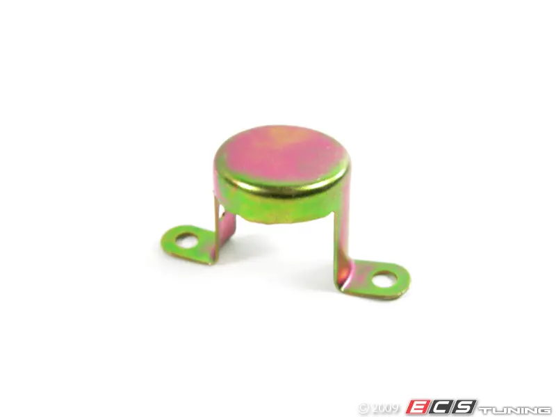
This is a plastic valve.
Image

Image

For some reason, I decided that it is placed at the junction of the upper wide part of the neck and the lower pipe. But no matter how hard I tried, the valve would not fit there. I just couldn't fit physically. So I decided to buy another neck with a valve. And after comparing them, it became clear that that valve cannot just fit into a regular neck. For it, a special landing ring is welded into the wide part of the neck, above the ventilation tube.
Image

Why in the ETK these two necks go under the same number, and it is indicated that the valve fits both of them - is not clear. Although externally and in terms of fastening, they are really the same. But the new valve turned out to be superfluous :)
Image

Well, let's talk about the types of necks - I also have a neck for an additional tank - it has a metal valve.
Image

I have already mentioned this tank before, and I will write briefly again in the relevant ETC section.

And the last type of necks is a plastic neck that combines the expansion tank of the tank ventilation system. I'm not exactly sure, but it seems that such necks were put on touring cars of the last years of production.
Image

So, I also brought the second neck into proper shape, as well as the tank. Although, the tank was still in excellent condition.
Image

Image

By the way, in the photo, there are four galvanized brackets that are placed at the places where the tank is attached - for some reason, they are not shown in the ETK at all.
Inside the tank is also clean and beautiful.
Image

We install the fuel pump on the rubber rings, then screw the fuel level sensor to it, and the fuel supply and return hoses, which I wrote about in the previous section. We put a protective hose on the fuel supply hose and fasten it with a tie, fix the hose with tape. We install brackets on the mounting holes of the tank.
Image

Image

I immediately screwed the brackets of the protective shield to the tank - it's more convenient that way.
Image

Everything is ready for installation. It is better to put the tank together. And by the way, it is much more convenient to put it before installing the rear beam and suspension. But in my case it didn't work out that way, so I had to tinker with it a bit. Let's start with the simplest. We insert the rubber spacer No. 18 (16 11 1 176 708), which I mentioned at the beginning, into the hole on the right rear spar.
Image

I didn't have it before, but now the neck is more protected from rubbing against the body.
Image

Next, a protective rubber coupling No. 17 (16 11 1 176 761) is also placed on the neck in place of the body bracket
We screw the neck with a bolt to the body bracket.
Image

Now tank. An important point - first you need to lay the wiring under the bottom to the level sensor and the pumping pump, because after installing the tank it will be very difficult to do it. Also, be careful not to pinch the ventilation hoses between the tank and the body.
Image

I already wrote that I had to remove the pump tank because it was in the way. The rear beam and suspension are also a bit of a hindrance, but we are not looking for easy ways! :)
As the practice of several attempts has shown, it is better to immediately tighten the two rear bolts with large washers, then insert the tank to these bolts with grooves, and press it back.
Image

Image

Then tighten the front central bolt on the cardan tunnel.
Image

Then tighten the front right nut and evenly tighten all four fasteners.
Image

Only then does the tank fall into place, after which we tighten the last front left bolt (without bracket) near the pump.
Image

We screw the fuel supply and return hoses to the corresponding fuel tubes. The tank is in place.
Image

Image

We connect the filler neck to the tank with a pipe on clamps. It's also not very convenient, but it's done!
Image

We connect a thick hose and a 6 mm plastic ventilation tube to the corresponding fittings of the tank. We connect the wiring connectors to the fuel level sensor and the fuel pump.
Image

We insert four clips, put a gasket.
Image

I also cut this pad from splenium, instead of the original one from paralon. And close the hatch with a lid on screws.
Image

The tank is installed.

The following is not a large division of ETK.
Heat-insulating screen
Image

Part #2 is not used. Apparently, this is a part for the tank before 83, which I wrote about above - in the photo on the right.
Image

Part No. 13 is no longer available for order, but although it makes its way through the ETK, it is most likely also used together with that tank before 83.
Image

Because there is simply nowhere to put it on my tank. My friend managed to buy it, but he also never found a place to install it.
So, there are two plastic shields that are attached to the bottom with three plastic nuts each, and a metal shield that is screwed to the tank with two brackets. The tank mounting bolts are also shown on the ETK diagram.
Here are all the details.
Image

We screw on the left shield that closes the tank and the pump, and also presses the fuel pipes.
Image

Image

But the right shield that closes the tank.
Image

Image

The brackets of the metal shield are screwed to the tank.
Image

Then we screw a metal shield to these brackets, which closes the connecting tube of the halves of the tank from the exhaust system.
Image

Image

The thermal screen of the exhaust system will then be attached to this shield.
Everything is installed.
Image

Image

The last unit of ETK remains - the first :)

Additional fuel tank
Image

Another interesting and rare option in the fuel system section is the S850 Additional tank.
I've written about her before, so I'll just remind you. This option was available on cars with the M20 engine before restyling and on the M3. An additional 15-liter tank was installed in the trunk behind the rear seat partition.
Image

Had his double neck
Image

The entire trunk lining is also different.
Image

I have most of it except the trunk liners, but I won't be installing that extra tank. Because this is the rare case when the original factory option is installed not "bolt-on", but with the use of welding and body drilling - the brackets must be welded to the trunk partition in place and a large hole drilled in the bottom for an additional filler neck. I have no desire to do this after painting the body. In addition, I don't have skins, and without them the look will not be aesthetic at all. Therefore, only the electrical part - wiring, and the sensor on the instrument panel will be installed. But that will be later. And we'll see... maybe someday I'll find the skins, then I'll install the tank. And for now it will lie as a collector's item :)
Image

This concludes the large section of the ETK "Fuel supply system".
Although there will be two entries on the adsorber and the fuel filter, but that is another chapter.
User avatar
martauto
E30 Zone Team Member
Posts: 6191
Joined: Wed Aug 31, 2005 11:00 pm
Location: leeds

Thu Oct 06, 2022 5:09 pm

WOW !!!
This is some epic adventure :clap: :clap: :clap: :clap:

The in depth detail is staggering to say the very least :banana: :banana:

Mart.
Only the E46 cab left now.
Just got too old.
User avatar
The_Glory
E30 Zone Regular
E30 Zone Regular
Posts: 381
Joined: Sun Feb 01, 2015 11:00 pm
Location: Kyiv, Ukraine

Wed Oct 12, 2022 7:05 pm

martauto wrote:
Thu Oct 06, 2022 5:09 pm
WOW !!!
This is some epic adventure :clap: :clap: :clap: :clap:

The in depth detail is staggering to say the very least :banana: :banana:

Mart.
Well, I said from the very beginning that I would write everything in as much detail as possible. Although everyone knows this already :)
User avatar
The_Glory
E30 Zone Regular
E30 Zone Regular
Posts: 381
Joined: Sun Feb 01, 2015 11:00 pm
Location: Kyiv, Ukraine

Wed Oct 12, 2022 7:11 pm

Assembly_26. ETK_51_Body equipment. (part 2)

Let's return to the ETC section ЕТК_51_Оснащение кузова

One of the smallest and simplest subdivisions of ETK - Protective edging/threshold overlays
Image

We are talking about door seals.
Image

I washed them, treated them with silicone spray and installed them a long time ago.
Image

Image

Image

Image

The front ones are in good condition, but the rear ones had to be glued a little. If possible, I will replace them if I find the whole ones, because the price of new ones is not at all pleasing.

Next, we go under the bottom to install everything that has not yet been installed there.

Heat insulation
Image

First, the heat shields of the catalyst and muffler.
Image

On my heat shields, chemical corrosion has severely damaged the mounting holes. I first tried to restore them with riveted aluminum covers, but then I found and bought whole heat shields. Just in case, I painted them with aluminum-zinc paint, and used stainless nuts and washers for fastening. This should reduce chemical corrosion between aluminum and steel.
The heat shield of the muffler is attached to the studs with four stainless M6 nuts.
Image

The heat shield of the catalyst is slightly different from my right front mount, but not critical. Perhaps it depends on restyling. It is attached to the gimbal tunnel with eight M8 bolts, and to the tank shield with two self-tapping screws.
Image

The heat shield is not fully attached, as it will still need to be removed to install the gimbal. I screwed it so that it does not lie "underfoot" in the garage.
The heat screen of the exhaust manifold pipes and the lower plastic protective shield of the engine compartment had to be slightly repaired.
In the original, some paralon was glued under the foil on the inner side of the screen of the exhaust manifold pipes. From dirt and water, he turned to ashes. In addition, chemical corrosion damaged this heat shield even more. So I bought almost a whole heat screen, but the paralon there was also in junk condition. It was possible to order a new one, but not very cheaply. Therefore, I decided that it would be easier, cheaper and better to "upgrade" the existing one - first of all, to get rid of the paralon that accumulates moisture.
So, first we remove the remains of paralon and glue, then sandblast.
Image

After that, many small holes appeared from corrosion. We glue them with aluminum tape.
Image

Cut a strip of the required size from heat-resistant non-combustible asbestos cloth.
Image

We glue it around the perimeter with aluminum tape.
Image

And with the same tape, we stick it to the screen instead of paralon.
Image

We glue the entire inner surface of the screen with aluminum tape.
Image

We paint the outer surface with aluminum-zinc paint.
Image

And we get a thermal screen that is no worse than a new one. And maybe even better.
Compared to my old screen. By the way, it has a large opening. I don't know what he is for. Maybe for right-hand drive cars?
Image

The lower plastic protective shield of the engine compartment is not quite right for me - it is for restyling. But according to the fastening, it is also intended for cars with air conditioning - with three large holes. Therefore, it will be like this for now.
Image

I had to seal the cracks a little.
Image

Even earlier, this is how I restored the broken right mount - using the same mount from my old shield, which I tore off at a railroad crossing.
Image

By the way, I also had to make a cutout for the hoses of the oil cooler. On restyling, they are located differently and do not interfere with the shield. A little "kolkhoz", but such...)
So, the heat shield of the exhaust manifold pipes and the lower plastic protective shield of the engine compartment are ready for installation.
Image

The screen is attached with two (or three in another version) plastic nuts #6 (51 48 1 923 999), which also fasten the sound insulation of the motor shield, and three metal washers #7 (51 48 1 884 110) to the bottom. There is also part #14 (07 14 6 949 380) on the ETC diagram, which actually also refers to the attachment of this screen. I had #14 washers, and I ordered new #7 washers, but as it turned out, either three #7 washers or three #14 washers are used. Maybe it depends on the year of release.
Image

Fastening with plastic nuts together with noise insulation.
Image

Mounting on the bottom - in my case, M6 studs were welded to the bottom, so #14 washers were more suitable for me. And the new No. 7 remained unnecessary.
Image

Image

The lower plastic protective shield of the engine compartment is attached to the body with four plastic nuts #11 (16 13 1 176 747). But the diagram still shows fasteners No. 12 and No. 13 - these are self-tapping screws and inserts for the side plastic shields. More on them later.
Image

I tried it on - it turned out well. Of course, I will install it after installing the motor.
Image

Image

Two plastic nuts on each side. But the side shields of the arches will be attached to these holes.
Image

So, now about the side shields.
Air duct
Image

As I said, I have the lower shield from restyling, so the side shields, accordingly, are also part #4 on the ETK diagram.
Image

But air channels #2 and #5 for blowing the brakes will not work for me, since the front apron does not have holes for them, and the BBS apron has them much lower. So, I will come up with something on the spot after installing the aprons. And for now, I bought Taiwanese analogues of shields - it won't be such a pity that they will be a "collective farm" :)
Image

Image

On the diagram, parts No. 1 and No. 3 are shields and ventilation ducts for cars of 83-85 years of production, which do not have a lower shield. Photo from the Internet.
Image

If I find it, I will gladly buy the correct lower shield for my case - for cars of 85-87 years of production. It is one-piece with side shields, and without ventilation channels. Photo from the Internet.
Image
By the way, blowing is provided under these shields. This seems to me to be a disadvantage of this option. After all, through the channels, the brakes cool better - I'm convinced by my own experience.
In an ideal case, I need it for an air conditioner - with holes at the bottom. So that there would be no "kolkhoz" at all ;)
Image

And for now, it will be as it was on the restyling, only with small improvements to the side shields and their channels ;)
Image

To finish already with the lower protection of the engine compartment, I will write about one more rare option that I have not yet found and bought. I will buy it if anyone has it, by the way ;)
Ref. protection panel fur south engine
Image

Metal engine protection for cars up to 1987 - 51 71 1 929 451 (photo from the Internet)
Image

Metal engine protection for cars after 1987 - 51 71 1 971 001 (photo from the Internet)
Image
Image

I'm not sure if these options are interchangeable and compatible with the corresponding plastic shields, but to find out, you need to find at least one ;) They are both available to order new, but the price of 400 and 1100 Euros, respectively, does not suit me at all...

I will write about other subdivisions gradually in the following parts.
DanThe
E30 Zone Team Member
Posts: 28641
Joined: Sat Sep 10, 2005 11:00 pm
Location: Staffs
Contact:

Sat Oct 15, 2022 2:47 pm

Great work, the early fuel tank is interesting, that small early tank is no way bigger than the 55 litre version, very strange as it looks to be around 40 litres
User avatar
The_Glory
E30 Zone Regular
E30 Zone Regular
Posts: 381
Joined: Sun Feb 01, 2015 11:00 pm
Location: Kyiv, Ukraine

Sun Oct 16, 2022 6:00 pm

DanThe wrote:
Sat Oct 15, 2022 2:47 pm
Great work, the early fuel tank is interesting, that small early tank is no way bigger than the 55 litre version, very strange as it looks to be around 40 litres
Thanks.
Yes, it is strange. Visually, according to the photo, it is clearly smaller than 55 liters. But in ETK, its volume is 58 liters, maybe 48?
Although, in ETK, the indicator on the dashboard until 83 is indicated as 55 liters. I think that this is another mistake in ETK. It would be interesting to see a photo of the dashboard on a car before 83, but I did not find such photos on the Internet.
User avatar
The_Glory
E30 Zone Regular
E30 Zone Regular
Posts: 381
Joined: Sun Feb 01, 2015 11:00 pm
Location: Kyiv, Ukraine

Thu Oct 20, 2022 3:19 pm

Assembly_27. ETK_61_Different additional wiring sets.

So, almost everything is installed under the bottom. Only the rear part of the body wiring remained - to the speed sensor in the gearbox, the brake pad wear sensor on the rear right wheel, the fuel level sensor and the boost pump, and the fuel level sensor to the additional tank.
This is where we will start the big ETK section General /car equipment

It has two subdivisions with the same name and schemes. I don't understand why they were separated, so in my opinion they can be considered together.

Various additional wiring sets

Various additional wiring sets

Image

Now I will write only about position No. 3, but in the course of assembling the machine I will return to other positions:
No. 1 - interior lighting wiring (to lampshades and "ends" of doors)
No. 2 - wiring of the speed sensor, brake pad wear (with a separate harness)
No. 3 - wiring of the speed sensor, fuel level and brake pad wear sensor (additional tank fuel level sensor, as an option)
No. 4 - wiring of the automatic fuse of electric windows (blocking of all electric windows)
No. 5 - wiring of the comfort relay of the electric windows (operation of the electric windows with the ignition off and the driver's door open)
No. 6 - wiring for daytime running lights (not sure, but it seems that the option of daytime running lights was provided for Scandinavian countries)
No. 7 - front door repair wiring (left and right)
No. 8 - Diode (I don't know what kind of diode it is)
No. 9 - wiring of the pyro cartridge of the airbag (for cars with an airbag)
No. 10 - wiring of the interior lighting delay timer (turning off the light in the interior after closing the door with a delay of several seconds)
No. 11 - I did not find it, it is probably not used

So, position No. 3 was in different versions. In my case, its top version, which includes, among other things, wiring to the fuel level sensor of the additional tank - 61 12 1 377 789
Image

Of course, I cleaned the wiring, "rang" all the contacts, treated the connectors with contact spray, replaced almost all the insulation. To fasten the wiring harness, you need six plastic clamps, and three clips to fasten the wiring to the brake pad wear sensor. You can see them in the photo.
Image

Connectors in the photo from left to right:
black square - fuel level sensor of the additional tank
white square - the main harness of body wiring
two black flat ones - the fuel level sensor and the boost pump
black round - brake pad wear sensor on the rear right wheel
black T-shaped with a rubber cap - speed sensor in the gearbox

We start with the speed sensor in the gearbox.
Earlier, in the gearbox section, I already wrote about the strange metal protective cap for the speed sensor connector (62 16 1 365 817)
Image

Judging by its photo, it is screwed together with the sensor and presses the connector. It's a strange decision, because apparently in order to remove the connector, you will need to unscrew the sensor. Otherwise, it will be very inconvenient to do it. Maybe that's why it was replaced with a rubber cap? These are just my guesses... but I have never seen him on cars, not even in a photo on the Internet. A strange detail, and given its inadequate price at $105, not needed at all, as for me! :)
So, we connect the speed sensor, close the connector with a rubber cap. We fasten the wire to the edge of the gearbox cover with a metal clip. By the way, ETK does not have it, but it is on almost all cars. Next, three plastic clamps on body studs under the trunk.
Image

And two more clamps of the same type above the rear beam.
Image

Wires to the fuel level sensor and the fuel pump are fixed with tape in a special groove on the body.
Image

And the wiring must be installed BEFORE installing the tank. Because if they fall out when installing the tank, it will be very difficult to push them between the tank and the body. By the way, probably for the same reason, they were laid in my cabin and pressed with a cover under the seat.
The wiring goes into the cabin through a rubber sleeve. The connector for docking with the main wiring is fixed with another plastic clamp.
Image

The wire for the fuel level sensor of the additional tank is pulled into the hole near the tank ventilation pipe and exits into the trunk.
Image

There it is connected to the sensor of the additional tank and is attached with metal clips to this tank. In my case, there will be no additional tank. Yet. Therefore, the sensor will simply lie somewhere behind the trunk lining.
Image

The last wire to the brake pad wear sensor is attached with three plastic clips to the right handbrake cable.
Image

After the brakes are installed, this connector is fixed with a special clamp on the metal bracket of the protective cover of the brake disk. But it will be in another section of ETK, on brakes.
The rear part of the body wiring is installed.
I also installed ABS sensors, but about them separately.


So, everything is installed under the bottom, except for the gimbal. Also, the brake calipers have not yet been installed - they are in the process of restoration.
Next, according to the plan - the rear part and body wiring.
User avatar
The_Glory
E30 Zone Regular
E30 Zone Regular
Posts: 381
Joined: Sun Feb 01, 2015 11:00 pm
Location: Kyiv, Ukraine

Fri Nov 11, 2022 1:48 pm

S428 First aid kit emergency stop sign with built-in storage box.

I didn't do anything with the car for almost a month. the Rashists with their rockets once again ruined everyone's plans and peace. Including me, I can't do anything without light in the garage, and they often turn it off. And in general, somehow there is no inspiration...
Therefore, today I will write about rarities. War, war, and the equipment, if possible, must be replenished.
I have had a box for a standard first aid kit and an emergency stop sign in the trunk for a long time. But the sign was from a newer BMW, and therefore did not fit in the box, and there was no factory first aid kit at all. And so, in the summer, flipping through a flea market, I accidentally found an ad in which it was sold in several versions. I chose the right version of the first-aid kit for the E30 based on its year of manufacture.
Image

Expiration date until June 1995.
Image

The first aid kit is in new condition - there are not even any scratches. Its contents are also completely preserved.
Image

Image

By the way, the contents are very different from our car first aid kits.
Image

There is even an instruction on providing first aid in the event of an accident.
Image

Image

Image

Image

Of course, this first aid kit will only be available as an original option. The car will have a fresh car first aid kit, completed according to the requirements of our rules.

The emergency stop sign is specifically for the E30 - its case has a special shape with a cutout the size of a box.
Image

There are cases with and without the BMW logo. I bought without the logo (an empty circle on the lid above the cutout). With a logo, it is significantly more expensive. There are no other differences. Maybe later I will buy one with a logo.
Image

The emergency stop sign is also in new condition.
Image

Image

Test in the garage ) I hope I never need it on the road...
Image

Now the S428 option is fully complete. The look of it on the car will be later, when I get to that.
Thanks to the seller for the good price and excellent condition - he also turned out to be a colleague on the E30 ;)

At the same time, other boxes arrived.
Image

Air conditioner hoses after electroplating.
Image

And some more details.
Image

Stainless self-tapping screws and sockets for them.
Image

And another batch of new bags.
Image

There is progress in the assembly, but not much. Today, the good news has already raised the mood - the inspiration to do something will appear! :)
User avatar
martauto
E30 Zone Team Member
Posts: 6191
Joined: Wed Aug 31, 2005 11:00 pm
Location: leeds

Fri Nov 11, 2022 2:14 pm

Was the good news the arrival of the "goodies" for the e30 or, the departure of the
"baddies" from parts of your country ?
Or both ?
I must see this when it is finished, its a work of art :clap: :clap: :clap: :clap:

Mart.
Only the E46 cab left now.
Just got too old.
User avatar
The_Glory
E30 Zone Regular
E30 Zone Regular
Posts: 381
Joined: Sun Feb 01, 2015 11:00 pm
Location: Kyiv, Ukraine

Fri Nov 11, 2022 2:30 pm

The good news is the second. And it would be even better if those bastards all died and let people live, work and rest in peace.
User avatar
martauto
E30 Zone Team Member
Posts: 6191
Joined: Wed Aug 31, 2005 11:00 pm
Location: leeds

Fri Nov 11, 2022 2:52 pm

The_Glory wrote:
Fri Nov 11, 2022 2:30 pm
The good news is the second. And it would be even better if those bastards all died and let people live, work and rest in peace.
:clap: :clap: :clap: :clap: :clap: :clap: :clap: :clap: :clap: :clap: :clap: :clap: :clap: :clap: :clap: :clap: :clap: :clap: :clap: :clap: :clap: :clap: :clap: :clap: :clap: :clap: :clap:

Mart.
Only the E46 cab left now.
Just got too old.
User avatar
The_Glory
E30 Zone Regular
E30 Zone Regular
Posts: 381
Joined: Sun Feb 01, 2015 11:00 pm
Location: Kyiv, Ukraine

Mon Nov 14, 2022 11:56 am

Paper ETK

The recording is just like that :) Although, as far as I'm concerned, it's about an interesting thing ;)
I have many E30 repair and service books in electronic form, I have several printed books, and I also have self-printed Etzold and ETM e-books. But, I have never seen and did not know that there is a paper version of the original BMW spare parts catalog - ETK! But he does exist! I accidentally saw such a book in our "E30 flea market" and bought it just out of curiosity :)

Image

It includes a fairly wide range of models.
Image

General information.
Image

Unfortunately, the book does not indicate the publisher and the year of its publication, but judging by the model range described, it is the 90s.
Image
Image

Of course, the publication is not official, but the catalog is very voluminous and detailed - someone's very painstaking work, especially at that time!
Image
Image
Image
Image


And this is just a gift from a friend - an idle speed regulator, and before restyling front seat belts.
Image

Now I have both rear and front seat belts with the same locks, and will correspond to the year of manufacture of the car. By the way, the last month of their production is 11.1985
Image

Another parcel will arrive soon, and then I will write something about the assembly. ;)
User avatar
The_Glory
E30 Zone Regular
E30 Zone Regular
Posts: 381
Joined: Sun Feb 01, 2015 11:00 pm
Location: Kyiv, Ukraine

Thu Dec 22, 2022 1:27 pm

Assembly_28. ETK_61_ABS wires

There is almost nothing new in the assembly - because of the cursed podarashists, there is light only for a few hours a day, and then in the morning or at night. And since my garage is in the basement, without light, in complete darkness, you can't do anything there... You probably need to make some kind of autonomous "emergency" lighting... That's why I'm writing about what I managed to do a little earlier.

So, we continue the ETK_61 section General electrical equipment of the vehicle

Namely, ABS wires
Image

The ABS system for the BMW E30 was available as an additional option, and for top models it was in the basic configuration. Therefore, in the first case, the ABS wiring was a separate harness connected through connector C302 for additional equipment. And in the second case, the ABS wiring was one whole harness with the main wiring. In my case, the wiring is from the top model 325i, so this is the second option. So, I will write about the main wiring later.
ABS sensors and their mounting in the ETK are shown for some reason not in the same section, but in sections on the chassis. I already mentioned them there.
Front (left and right differ in wire length - the right is longer):
Image

Rear (left and right are the same):
Image

Therefore, there is almost nothing to write about. But there are some nuances regarding the installation and fastening of the sensors.
The ETK diagram shows the fasteners.
Image

Part No. 2 (61 13 1 371 074) - their number is not quite correct in the ETK. For cars with 6-cylinder engines, you need 2 of them - for the left and right front sensors.
And part No. 3 (61 13 1 374 899) is used only on cars with 4-cylinder engines for the left front sensor (photo from the Internet).
Image
And part #2 (61 13 1 371 074) is also used for the right sensor. That is, for 4-cylinder, you need 1 piece of each.
Part No. 4 (61 61 1 356 460) - their number is not correctly indicated in the ETK. You need 2 of them - for the left and right front sensors. They are available to order, but I did not like the price of 25-30 euros per piece - another inadequate price. I did not find analogues. But earlier I ordered similar rubber rings for windshield wipers (61 61 1 353 754). I tried them on - they fit almost perfectly! The difference is 1-2 millimeters in diameter. And the price difference is 3.5 Euro per piece. For me, the pricing logic for these two almost identical parts is not clear :) Of course, I ordered two more 61 61 1 353 754.
Part No. 5 (12 52 1 276 147) - 1 piece, D=16.8 mm (blue). It is available to order, but as it turned out, it can be bought at almost any auto store much cheaper. These are universal staples that fully correspond to the original ones in terms of size and color, depending on the size. They are still used a lot, so I bought them right away with a stock of different ones - gray, green, blue, red, yellow - in order of increasing size.
Part No. 6 is a repair piece of wire with a connector. It seems to me that it is better to buy the entire sensor at once. I bought the rear ones in very good condition, because mine were very damaged in many places.

Therefore, the installation of sensors. Everything is elementary.
Front left.
We clean the seat, insert it as far as it will go, and fasten it with a screw.
Image

We fix the wire with a loop on the rack in a plastic holder and in a metal bracket.
Image

I will say right away that it is not necessary to fix with two loops on the metal bracket, because then the length of the wire is not enough. Then I left only one loop. I don't know why they made two rubber clips and two grooves in the bracket...
We knock out the metal plugs in the body (fortunately, I did it before painting). We treat the hole with wax and install the rubber rings I mentioned above. We pass the wire through them into the engine compartment.

Image
As you can see, the wire is short. Therefore, we leave only one loop on the rack, and pull the wire to the connector holder, which is installed on the body in a special hole.
Image

Everything is also on the right side.
Image
Image
Image

We pull the wire to the connector holder installed on the spar in a special hole. Next, we install a blue bracket for wiring on the right spar.
Image

The front sensors are installed.
Image

It was a little more difficult with the rear ones. My body was manufactured at the end of 1984 under the M10 engine with a carburetor. It seems to me that ABS was not available at all for this configuration. Perhaps that is why there are no holes or plugs for the rear sensors in the body. Previously, the wiring of the sensors was pulled through the holes for the body wiring, due to which they were not sealed and dust and dirt got inside. I forgot to make these holes before painting... I wanted to leave it as it was, but then I still decided to do it as needed. For this, I bought a special drill (a cool thing, by the way), measured the rubber sleeve - it turned out to be slightly larger on the newer sensors than it was on my old ones.
Image

Therefore, the hole had to be drilled larger than was provided for on the vibration isolation. Grinding his teeth out of anger at himself, he began to drill very carefully...
Image

But everything turned out fine :) I treated the holes with zinc, primer and tinted them.
Image

Installing the rear sensors is also very easy.
Rear left.
We clean the seat, insert it as far as it will go, and fasten it with a screw.
Image

We fix the wire on the lever with two plastic clips and a rubber sleeve in the metal bracket of the lever.
Image

We fix the wire on the beam with a plastic bracket. By the way, the fixing points on the wire are marked with white paint.
Image

We treat the hole with wax and install rubber bushings with a wire.

Everything is also on the right side.
Image
Image

We lead the wire with the connector into the cabin under the back seat.
Image

After laying the main wiring with the ABS wiring, it remains only to connect the connectors of the sensors and the hydroblock. The ECU will be installed after the torpedo is installed.

Next, I will probably write a little more about the wiring, and then there will be something about the assembly as well.... The damn Muscovites do not allow you to do anything normally.
User avatar
The_Glory
E30 Zone Regular
E30 Zone Regular
Posts: 381
Joined: Sun Feb 01, 2015 11:00 pm
Location: Kyiv, Ukraine

Thu Dec 22, 2022 6:07 pm

Assembly_29. ETK_61_Wire bundles (Battery)

Next, we continue the ETK_61 section General electrical equipment of the vehicle

Next subsection Wire bundles (Battery)
Image

On all diesel and top models of the E30, the battery was located in the right niche of the trunk - for better weight distribution between the axles.
My car also had it in the trunk, but it wasn't done quite right. The "plus" terminal was not screwed in its place, but on the platform for the battery under the hood, the "minus" terminal was also not screwed to the rear fender, but to the rear bumper attachment, and the battery itself in the niche was not fixed in any way and just lay there on a piece of paralon and a cover that goes over the tank. Of course I fixed it all and made it the way it should be. Everything was cleaned, fasteners were galvanized, what was missing was replaced with stainless steel.
Image

Parts #1 and #2 are not used, they are for cars with a battery under the hood.
The set includes the main cable with a thin duplicate wire (#3), cable to the starter (#4), "minus" terminal (#5), "ground" wire to the engine (#6), terminal bracket with a cover (#7- 9), M6 fasteners for the internal hexagon (#10, 11), plastic protective cover (#12), rubber sleeve (#13) and 50A fuse (#14).
The ETC diagram does not show the attachment of the terminal bracket - three M6 bolts with nuts and washers, the attachment of the "minus" terminal and the "ground" wire - an M8 bolt and nut with washers.
So, let's start with the front. We treat the hole for the cable with wax, and install a rubber sleeve (#13) together with the cable (#3) into it. The terminal bracket (No. 7-9) must be installed after installing the noise insulation of the motor shield. It is also important not to forget to insert three M6 bolts into it first. I forgot. :) I had to unscrew it. The bracket is attached to the holes with two bolts under the internal hexagon and nuts on the other side (No. 10, 11).
Image
Image

A duplicate thin wire is screwed to the upper pin, and the main cable is pressed to the two lower ones.
Image

By the way, the thin and main cables are parallel and come from the same terminal. The 50A fuse (No. 14) is located only on a thin wire - in its rear part, under the casing.
Image

We screw the cable to the starter (#4) to the terminal of the main cable (#3)
Image

We put a plastic cover on the terminals and close it.
Image

That's all under the hood at this stage.
Image

The starter cable has a protective corrugation - check its condition.
Image

In the cabin, we lower the cable to the threshold and lay it along the threshold to the back seat.
Image
Image
Image

Under the rear seat, the cable runs between the body and the pipe for the tank ventilation pipes. A protective corrugation is installed in this place - we check its condition.
Image

Of course the cable will be secured with clips and clamps along with the other wiring after it is installed.

Through the hole in the partition, we lead the cable into the trunk. There it is covered with a protective plastic cover (#12). The cover is inserted into the opening of the partition, and in the rear part is attached to the body pin. It will later be secured with a plastic nut along with the arch guard. This will be discussed in the next post.
Image

The "minus" terminal is screwed to a special bracket on the rear wing.
Image

Everything is ready to install the battery.

The "minus" wire to the engine remains. We screw it to the bracket of the left spar.
Image

I restored mine. He looked like this.
Image

Sanded, covered with zinc and replaced the heat shrink.
Image

By the way, about the "minus" wires - somewhere on the Internet I found a reasonable photo of all of them with a description - thanks to the author.
Here are a bunch of other ground wires that you should also replace while you're at it. In general, you can use any thick wire with a suitable mounting hole, but for those purists at heart:
Image
12-52-1-285-011 Alternator ground cable, however I used it to ground the A/C compressor to the engine block.
12-52-1-312-124 Generator mass cable (red).
12-51-1-714-039 Grounding of the engine to the frame.
65-31-1-286-069 Rocker cover, but instead I used 12-42-7-551-714 with e9x because of the factory 90* bend. Also, it looks a lot nicer =).
12-61-1-311-511 Oil level sensor mass. It attaches to the oil pan which simulates the oil level as our machines do not have a sensor. (for boys m3/s14).
65-31-9-055-973 Radio-protective grounding tape.
65-31-1-286-068 Hood grounding belt.
12-42-7-551-714 from e9x which I used as ground to cover the rocker instead of the ugly 65-31-1-286-069 cable.
Next, about the battery and a little more about the wiring.
User avatar
martauto
E30 Zone Team Member
Posts: 6191
Joined: Wed Aug 31, 2005 11:00 pm
Location: leeds

Fri Dec 23, 2022 1:15 pm

Thanks for sharing this with us, the detail is fantastic and it can not be something which is priority for you at the moment.
Are yo still getting parts for this and if so, where the hell from ??

Mart.
Only the E46 cab left now.
Just got too old.
User avatar
The_Glory
E30 Zone Regular
E30 Zone Regular
Posts: 381
Joined: Sun Feb 01, 2015 11:00 pm
Location: Kyiv, Ukraine

Sat Dec 24, 2022 4:06 pm

Of course, this is not the main priority at the moment, but something needs to be done. Because after the new year it will be 5 years since I took it apart for major repairs! I didn't think it would take so long... Somehow everything didn't go as planned...

I always order original parts through my supplier directly from Germany, without intermediaries. This is even cheaper than ordering from our official BMW dealer. Now there is a problem with the delivery time. My last order was at the beginning of December, but it was moved to January. Because of this, there are also delays in the assembly...

I order other parts and analogues in local online stores. No problem with that.
User avatar
martauto
E30 Zone Team Member
Posts: 6191
Joined: Wed Aug 31, 2005 11:00 pm
Location: leeds

Sat Dec 24, 2022 5:25 pm

Thank you sooooooooooooo much for the reply.
Keep it going please , this is very important !!!!

mart.
Only the E46 cab left now.
Just got too old.
User avatar
The_Glory
E30 Zone Regular
E30 Zone Regular
Posts: 381
Joined: Sun Feb 01, 2015 11:00 pm
Location: Kyiv, Ukraine

Mon Jan 23, 2023 12:50 pm

Lately, because of the damned Muscovites, I have been dealing with urgent household chores - alternative and autonomous lighting, power supply and heating. It took quite a lot of time and money, so again the progress on the assembly is not significant at all. Mainly also on electricity.

Assembly_30. ETK_61_Battery

Next, we continue the ETK_61 section Общее е/оборудование автомобиль

The following subsection BMW battery. with electrolyte
Image

According to ETK, 65Ah batteries were installed on the 325i, but I had 70Ah. My battery completely died after several years of idleness in the garage. Tried to charge it, but to no avail. So just a photo for a picture :)
Image

Now, because of these blackouts, is not the best time to buy a battery or generator - the prices are inadequate. Maybe a little later I will buy a new one. I haven't decided yet - whether it's an original BMW or just an Exide that comes in the original.

In addition to the battery itself, there should also be its fastening. I didn't have it before, and the battery was just lying at the bottom of the right trunk compartment. Of course, I have now fixed it and installed all the necessary parts.

Battery
Image

Parts #3 and #10 come with the new battery, so they are not in the photo yet. Parts #8, #9 and plastic spacer #11 are fasteners used only when installing the battery under the hood. Part #13, apparently, is not used at all on the E30.

So, the mounting kit includes tank #4, gas discharge hose #5, hose fitting #12, pallet #6 and bolt with plate #7.
Image

There are nuances in some details.
Tank No. 4 for before restyling and after restyling is different. By 87 (61 21 1 374 963) it is much smaller, but it is no longer available for ordering. After year 87 (61 21 1 376 693), the tank is larger and serves as an additional support for the pallet. In addition, it is easier to find, and it fits normally on pre-restyling cars, so I don't see the point in looking for tanks specifically for pre-restyling.
Image

In the photo, you can see another piece of white foam - it is not by chance ;) But according to ETK, it is in another section, so I will write about it there. In short, it is also an additional support for the pallet. Although it looks like a "collective farm", this is a factory solution to a problem that was probably not taken into account right away. :) Although, I'm not 100% sure about this, but I can't imagine any other use for it... If someone has it left from the factory and it's somehow misplaced, or in the wrong place - please correct me.
Image

But this is what the problem itself looks like - without this support, the mounting eye on the pallet breaks under the weight of the battery.
Image
Image

As practice shows, this is how most of these pallets look on pre-restyling cars, because that foam has not been preserved. Perhaps that is why they made a larger tank on the restyling, so that it would be a support for the pallet. By the way, pallets for restyling and restyling differ precisely in this eye. Someone already glued my pallet, but it was very unsuccessful - it did not even fit into its place. That's why I redid everything - it doesn't look perfect, but it performs its function well. The hole had to be slightly enlarged, because the pin was not welded exactly. Maybe later I will buy a new one.
Image
Image

Another point that is not clear - there is no rubber seal in the ETK instead of the body plug, for installing the tank. The diameter of the hole in the body is much larger than the diameter of the tank nozzle. I don't know, maybe the hole in the body is smaller on the restyling, but I selected the size of the rubber plug, cut a hole for the nozzle in it, and it all fit perfectly and tightly on the body. By the way, I also did not find smaller plugs in the left and right trunk niches in ETK, so I also simply selected them by size in a car store. This is what it looks like from below.
Image

The hose (61 21 1 377 745) is sold by 1 meter, although half will be enough.

Fastener No. 7 (61 21 7 564 274) consists of three parts, but each of which must be ordered separately:
61 21 7 564 274 - plate 1 pc.
61 21 7 577 620 - bolt 1 pc.
07 14 9 158 226 - locking washer 1 pc.

The bolt is inserted into the plate, then a locking washer is screwed onto it, which prevents the plate from jumping off the bolt.
Image

And the last nuance - the ETK does not show the bolt, washers and nuts that are used to fasten the pallet - one M8 bolt, three 8 washers and two M8 nuts.

Battery mounting assembly.
Image

All that remains is to buy and install a new battery.
User avatar
The_Glory
E30 Zone Regular
E30 Zone Regular
Posts: 381
Joined: Sun Feb 01, 2015 11:00 pm
Location: Kyiv, Ukraine

Mon Jan 23, 2023 6:40 pm

Assembly_31. ETK_61_Wire contacts clamp

Next, we continue the ETK_61 section Общее е/оборудование автомобиль

We will talk about the "general" subdivisions of ETK, in which numerous wires, connectors, contacts, foams, clamps, clips and other wiring fasteners are listed. I don't see the point in writing everything in detail on each pin, so I'll just write what and how I use when repairing and restoring the wiring.

Wire
Image

When replacing or supplementing wiring, I use original wires from donor pieces of E30, E34 and newer BMW wiring. I choose the wires according to the colors given in the ETK. Although wires of many colors can still be ordered new, but I don't see the point in this.
Image

Connector plug housing
Image

I also take some connectors and pins from them from donor wiring. There are a lot of their standard sizes in ETK, so it is difficult to understand their numbers and quantities - it is easier to take and try on in fact. In addition, many of them are no longer available to order, or are unreasonably expensive.
My main problem (like most) is with the door connectors. Therefore, I bought several such donor connectors, as well as a C302 connector for additional equipment to equip my own, and a C103 connector. I bought another set of pin removers because they are not very strong.
Image

A small offtop - I will show, using the example of donor connectors, how some people repair and "upgrade" the wiring ;) After such wonderful electricians, then the devil will break his leg in that wiring :)
For example, judging by everything, this is the docking of the restyle wiring with the connector to the restyle - everything is simple - everything was cut off, and then everything was soldered. They didn't hear about the replacement of pins :) So this black cuttlefish came out:
Image
Image

Now the door connector is amazing - the wires of the central lock are all in one twist - and for grounding! )) And a bunch of amazing twists of different colors!
Image
And the "logical" continuation - the red wire through the insert with two turns to the factory brown ground wire! ) How it somehow worked there - I can't imagine! ))
Image

The only normal C302 connector was simply cut off.
Image

So, back to my wiring. I washed, cleaned, cut off all the "masterpiece" twists, and prepared donor connectors, foam removers, and new flat contacts.
Image

As I said, the main problems I had were with the door connector. As practice shows, almost everyone has such a problem - the rubber corrugation from old age allows water to flow down the rack, the contacts oxidize and eventually rot completely. Especially those with constant power. Because of this, these connectors are difficult to remove, and especially when people do not know how to remove them, and disassemble them in an absolutely barbaric way. Judging by the condition of those that I saw - they are practically torn out. So, I will show how to disassemble them correctly and carefully - maybe someone will need it.
First, it is good to fill the connector with WD-40 or something similar. Wait, and then sort it out. Remove the rubber corrugation, press the two lugs on the sides and pull out the door part (No. 14 on the ETK diagram) from the body (No. 15 and No. 16). Next, carefully press the three latches on the case and squeeze the connector into the niche of the front speaker.
Now, how to disassemble the body connector to replace the pins in it.
Door connector C405 (left) and C404 (right) are structurally similar, and consist of three parts (although for some reason only two are shown in the ETK)
No. 15 - outer case - 61 13 1 380 587
No. 16 - inner case - 61 13 1 375 690
lining of the inner case
Image
Image

To get to the pins, press the two latches on the sides.
Image

We push them up along the guides
Image

We pull out the lining of the inner case, and we already have access to the pins.
Image

But it is much more convenient to change the pin by separating the inner case from the outer one. To do this, from the side of the wiring, insert two thin screwdrivers into the grooves on the sides, press the latches with them, and pull out the inner housing. Fully disassembled door body connector.
Image

By the way, 4 pins remain in the outer case. This is done, for convenience, to separate the main wiring and the wiring of various additional options. I will write about this in the corresponding section with a detailed explanation.
Image

When replacing pre-styling headlights with restyling ones with lenses, you need to change all their connectors. This time I did everything properly, without the "kolkhoz". Maybe someone will also find it useful:
The body of the connector is straight:
61131378400 straight black
61131378401 straight white (high beam)
61131378402 straight gray (sidelight)
61131378403 direct yellow (low beam)
A straight pin with a piece of wire:
61130007441 straight thin (0.5-1.0mm2)
61130007442 straight thick (1.0-2.5mm2)

Corner connector body:
61131378416 angular black
61131378417 corner white (main beam)
61131378418 corner gray (sidelight)
61131378419 corner yellow (low beam)
Corner pin with a piece of wire:
61130007445 angular thin (0.5-1.0mm2)
61130007446 corner thick (1.0-2.5mm2)

I will write about all other connectors and pins that I will change or add as the case progresses, in the appropriate sections.

Various Parts for Wiring Repair[/URL ]
Image

Everything is simple here - Tesa insulating tape, which comes in the original - PVC, fabric and Mylar, heat shrink and matches :)
Image
I wrap the harnesses with insulating tape without gaps - I like it better that way.


[URL='http://ru.bmwfans.info/parts-catalog/E3 ... le_holder/']Кабельные зажимы

Image

I collected all the fasteners for wiring - judging by the photos on the Internet, different clamps were used in different years, so I will put them at my discretion. The quantity in ETK is not indicated, so I will watch as the case progresses - I hope that it will be enough.
Image

Item No. 1 - plastic staples for wiring of different diameters and corresponding colors. Sold at any auto store.
Detail #2 - I don't know what it is for, I didn't find it. If anyone knows, please let me know.
Detail No. 3 - clamps for fastening the wiring along the thresholds. In each threshold, I counted 11 holes suitable for their installation. But I think that at least 5-6 pieces for each side will be enough.
Detail No. 4 - a clamp for fastening the wiring. Judging by the photo on the Internet, it was used on later machines.
Detail No. 5 - bracket for door wiring. At least I had him there.
Detail No. 6 - a clamp for attaching the wiring to the openings of the body. Judging by the photo on the Internet, it was used on earlier machines. The older ones have the shape of "herringbone trees", and the newer ones have the shape of "ladders". About 10 pieces are needed.
Detail No. 7 - a clamp for attaching the wiring to the studs of the body. Judging by the photo on the Internet, it was used on earlier machines. The older ones have the shape of "herringbone trees", and the newer ones have the shape of "ladders". About 20 pieces are needed.
Detail No. 8 - a clamp for attaching the wiring to the studs of the body. Judging by the photo on the Internet, it was used on earlier machines. I had them installed outside under the bottom. According to ETK, for some reason they have the same number with clamps #7, although in fact they are different.
Part No. 9 - ordinary screed 4.8/300mm
Detail No. 10 - a clamp for fastening the wiring. I did not find such a thing. Probably something similar to the blue collar in the photo. If anyone knows, please let me know.
Part No. 11 is a clamp for attaching the wiring to the torpedo. The older ones have the shape of "herringbone trees", and the newer ones have the shape of "ladders". About 10 pieces are needed.
Item No. 12, 13, 14 - metal staples of different diameters.
Part No. 15 - a clamp for fastening the wiring. Judging by the photo on the Internet, it was used on later machines.
Part No. 16 - was not used.
Part No. 17 is a bracket for attaching C103 and C302 wiring connectors. It was used on cars before restyling.
Part No. 18 - a bracket for fastening the wiring. It was used on cars after restyling, it was put in place of part #17.
Part No. 19 is a bracket for attaching C103 and C302 wiring connectors. It was used on cars after restyling.
Part No. 20 - was not used.
Part No. 21 is a plastic nut with lugs for wiring.

That's it with "common" units.
Details about wiring and its installation in the following sections.
User avatar
The_Glory
E30 Zone Regular
E30 Zone Regular
Posts: 381
Joined: Sun Feb 01, 2015 11:00 pm
Location: Kyiv, Ukraine

Mon Jan 23, 2023 9:00 pm

Assembly_32. ETK_61_Different additional wiring sets.

Various additional wiring sets[/URL ]
Image

Recently, I already wrote about this section of ETK, or rather about one item from it - No. 3. Now I will continue about other positions:

No. 1 - interior lighting wiring (to lampshades and "ends" of doors) - 61 12 1 373 554.
Image
Image
The wiring to the left and right shades is the same. In addition, I made similar wiring for the third shade, which I installed a long time ago, near the interior mirror, instead of the plug. I don't know - why wasn't this done at the factory?

No. 2 - wiring of the speed sensor, wear of the brake pads (with a separate harness). On my car, it is replaced by #3.

No. 3 - wiring of the speed sensor, fuel level and brake pad wear sensor (additional tank fuel level sensor, as an option). I have already written about her before.

No. 4 - wiring of the automatic fuse of electric windows - 61 12 1 370 980.
Image
Image
Power cord for electric windows through the fuse button. The button blocks the operation of all electric windows.

No. 5 - wiring of the comfort relay of the electric windows (operation of the electric windows when the ignition is off and the driver's door is open) - 61 12 1 376 064.
Image
Relay:
Image
Found another one, without a relay.
Image

No. 6 - wiring for daytime running lights (not sure, but it seems that the option of daytime running lights was provided for Scandinavian countries). I don't have one.

No. 7 - front door repair wiring (left and right). I don't have a repair room either, but there is a standard one, more about it later.

#8 - Diode (I don't know what kind of diode it is)

No. 9 - wiring of the pyro cartridge of the airbag (for cars with an airbag). I don't have it yet, but maybe soon. Although, I will not put an airbag - just for the collection of options.

No. 10 - wiring of the interior lighting delay timer (turning off the light in the interior after closing the door with a delay of several seconds) - 61 12 1 380 379.
Image
Relay:
Image
In the photo, the wiring is woven separately. I have wiring in the "top" configuration, so the same wiring is woven into the wiring harness of the central lock, so I will also write about it later.

No. 11 - I did not find it, it is probably not used

The next subdivision.
[URL='http://ru.bmwfans.info/parts-catalog/E3 ... ing_sets_3']Various additional wiring sets

Image

No. 1 - heater wiring. I will have an air conditioner, so the wiring will be different - about it in the appropriate section.

No. 2 - electric sunroof wiring - 61 12 1 369 295.
Image
Relay:
Image
By the way, this relay has an interesting marking of the contacts - in colors, according to the color of the wires:
Image
Image

No. 3 - wiring of an additional electric fan. I will have an air conditioner, so the wiring will be different - about it in the appropriate section.

No. 4 - wiper wiring. In mine, of course, it is part of the main wiring, and is connected to the fuse box.
Image

No. 5 - airbag wiring (for cars with an airbag). I don't have it yet, but maybe soon. Although, I will not put an airbag - just for the collection of options.

That's it for additional wires. I will write about their installation together with the installation of all wiring.
Next time I will write about the so-called "electric package" - electric windows, electric sunroof, electric mirrors, central locking, interior lighting timer, and heating of the driver's lock.
User avatar
The_Glory
E30 Zone Regular
E30 Zone Regular
Posts: 381
Joined: Sun Feb 01, 2015 11:00 pm
Location: Kyiv, Ukraine

Thu Jan 26, 2023 3:27 pm

Assembly_33. ETK_61_Bundles of wires (electric package)

Next, we continue the ETK_61 section Общее е/оборудование автомобиль

The next subdivision is the so-called "electric package".

Wire bundles (electric package)
Image

This is a set of options combined into one interior wiring harness and door wiring. This set includes the following options:
- electric mirrors
- electric windows (two front or all four)
- central lock
- electric window comfort relay
- electric sunroof
- interior light switch-off timer
- heating of the driver's door lock

The wiring of the last four options was already shown in the previous section.
Depending on the configuration of the machine, there may be different combinations of these options. In my case - the "top" configuration, so they are all present.
The wiring of the electric passenger mirror on early cars was a separate harness (No. 1 and No. 2 on the diagram), and later it went together with the wiring of the central lock. By the way, in my car after its purchase, they were both, but the mirrors still did not work :)
So, let's move on to the main wiring of the "electric package" (No. 6 on the diagram).
I bought the wiring for four electric windows a long time ago, and the "package" included the remains of the central locking wiring. It was necessary to separate them. My garage is in the basement, it's dark there even during the day, and there's nothing to do without light. That's why I pulled the wiring to the house - my wife probably didn't like it very much, but she didn't kick it out - I'm grateful to her for that :)
Here is such a tangle of wires:
Image

I untangled everything superfluous from it - the remains of the wiring of the central lock, with the main connector cut off and the rear part for the tank and trunk.
Image

And the remaining wiring for four power windows is in fairly good condition. Replaced only two pins on the right front.
Image

Even the tag with the number - 61 12 1 380 369 - corresponding to the year 85-86 has been preserved. What is needed.
Image

But under this number, the same "electrical package" is available in the ETC - "For cars with an electric window lifter and a central lock." Therefore, I took my wiring from the garage, from which I also separated the wiring of the two front power windows.
Image

And there remained a "package" of wiring for electric mirrors, central locking, a timer for turning off the interior light and heating the driver's door lock.
Image

On the left, the wiring of the timer for turning off the interior light and heating the driver's door lock is woven.
Image

On the right is the central lock and electric mirrors.
Image

Rear door connectors, and connectors of the central lock on the hatch of the tank and the trunk.
Image

I already said above that depending on the equipment of the car, there may be different combinations of these options. And to make it easier to combine them, the front door connectors C405 (left) and C404 (right) consist of two connectors - external and internal. Thanks to this, the wiring of the "electric package" can be very easily separated from the main body wiring - it is enough to simply separate the inner part from the outer part (how to do it correctly, I wrote in previous entries).
The outer part remains on the body wiring - there are only three wires for powering the entire "electric package":
red/black - constant power
green/black - power from the ignition switch
brown - mass

The inner part remains on the wiring of the entire "electrical package" and can be replaced completely, or supplemented with pins for various options from the "electrical package".
Image

If I had known this before, I wouldn't have pulled all that wiring through the hole in the motor shield! )))

On the right, in the outer part, the mass and three wires of the right electric mirror remain.
The wiring for electric windows and/or central locking remains in the interior.
Image

By the way, on the inner parts on both sides, as a rule, there are two more wires with 1-pin connectors (blue and white) - this is the audio wiring for the front tweeters in the doors.

The tag on my wiring was also preserved, but it was of little use - the number was completely rubbed off. Logically, it should be the same - 61 12 1 380 369
Image

So, we put the wires one on top of the other.
Image

We put it in one bundle.
Image
Image
Image
Image

We rewind it with the original fabric insulating tape, and we get a beautiful harness of a complete "electrical package".
Image

With two tags :)
Image

And now, useful (I hope so) information on connectors.

Front left side:
Image

1.1 - C405 internal door connector
1.2 - C405 external door connector
2.1 - tweeter +
2.2 - twitter -
3 - standard alarm
4 - power supply of power windows C302 (Q)
5 - grounding of electric windows G200
6 - door stop for the electric window comfort relay
7 - power supply of the central lock C302 (D)
8 - grounding of the central lock G200
9 - block of the central lock
10 - timer relay for turning off the interior light and heating the driver's door lock
11 - driver's door stop
12 - contact for the driver's door end stop

Front right side:
Image

1.1 - C404 internal door connector
1.2 - C404 external door connector
2.1 - tweeter +
2.2 - twitter -
3 - door stop for the electric window comfort relay

Power window buttons:
Image

1 - front left electric window regulator button
2 - button of the front right electric window lifter
3 - button of the rear left electric window lifter
4 - button of the rear right electric window lifter
5 - button to lock the rear power windows

Rear:
Image

1 - C401 rear left door connector
2 - C402 rear right door connector
3 - central trunk lock
4 - the central lock of the tank hatch

In order for this entire "electrical package" to function, each door must also have appropriate wiring.
Image

Driver's side (No. 3 on the diagram) - wiring comes in different configurations. I have, again, the "top" version with a full list of "electric package" options. In addition, it also contains wiring for the magnetic lock of the standard alarm system - 61 12 1 385 855.
Image

1 - C405 door connector
2 - electric mirror
3 - button for adjusting electric mirrors
4.1 - tweeter +
4.2 - twitter -
5 - electric window regulator
6 - central lock
7 - door lock stop
8 - timer for turning off the interior light and heating the driver's door lock
9.1 - magnetic lock of standard alarm system
9.2 - unit of standard alarm system

C405 pinout:
Image

Passenger side (No. 4 on the diagram) - wiring comes in different configurations. Happens only with an electric mirror. It happens completely without wiring, with a mechanical mirror. And it happens, even, without a mirror at all. I have, again, the "top" version with a full list of "electric package" options - 61 12 1 385 856.
Image

1 - C404 door connector
2 - electric mirror
3.1 - tweeter +
3.2 - twitter -
4 - electric window regulator
5 - central lock
6 - door lock stop

C404 pinout:
Image

The rear left and right sides (No. 5 on the diagram) are the same - the wiring is in the same configuration for a complete "electrical package" - 61 12 1 375 794.
Left:
Image

Rights:
Image

1 - C401 left or C402 right door connector (similar)
2 - power window button
3 - electric window regulator
4 - central lock

Pinout C401 or C402:
Image

The entire wiring of the "electric package" looks like this:
Image

In addition to connecting to the door wiring, and powering through the external connector C405, the "electric package" is also connected to the connector of additional equipment C302:
- comfort relay of electric windows - on pins Q (white/black) and Z (red/yellow) - power supply for the operation of electric windows when the ignition is off and the doors are open;
- central lock - on pin D (red connector with green wire) - power supply for emergency opening of the central lock;
Image

Also, the parts of the "electric package" are connected to each other through the wiring of the button of the emergency fuse of the power windows.
Image

1 - power supply from the relay to the emergency fuse button
2 - power supply from the relay to the power sunroof
3 - power supply from the emergency fuse button to the power windows
4 - emergency fuse button

Perhaps this is all I know about the "electric package" E30.

I'm almost done rewiring the other optional extras now. Then I have to finish with C302 and C103 on the main wiring, which has been hanging in the garage on the wall for two years. Then mount and connect it all. Then maybe body assembly will go faster...
steve_k
E30 Zone Team Member
Posts: 8044
Joined: Fri May 23, 2008 11:00 pm
Location: in the vale of mansfield
Contact:

Thu Jan 26, 2023 5:40 pm

WOW definitely no half measures in this build, i reckon the car will be "as new" when finished.
if it's got t*ts or wheels it's bound to be trouble...............prove me wrong.
getting oral sex off an ugly person is like rock climbing.....don't look down ;)
User avatar
The_Glory
E30 Zone Regular
E30 Zone Regular
Posts: 381
Joined: Sun Feb 01, 2015 11:00 pm
Location: Kyiv, Ukraine

Fri Jan 27, 2023 12:48 pm

steve_k wrote:
Thu Jan 26, 2023 5:40 pm
WOW definitely no half measures in this build, i reckon the car will be "as new" when finished.
Thanks. The main thing is to reach the final...or survive to the final...
steve_k
E30 Zone Team Member
Posts: 8044
Joined: Fri May 23, 2008 11:00 pm
Location: in the vale of mansfield
Contact:

Fri Jan 27, 2023 5:25 pm

The_Glory wrote:
Fri Jan 27, 2023 12:48 pm
steve_k wrote:
Thu Jan 26, 2023 5:40 pm
WOW definitely no half measures in this build, i reckon the car will be "as new" when finished.
Thanks. The main thing is to reach the final...or survive to the final...
i know exactly what you mean, it may seem insurmountable at points but the end result is worth it.
if it's got t*ts or wheels it's bound to be trouble...............prove me wrong.
getting oral sex off an ugly person is like rock climbing.....don't look down ;)
User avatar
martauto
E30 Zone Team Member
Posts: 6191
Joined: Wed Aug 31, 2005 11:00 pm
Location: leeds

Sat Jan 28, 2023 3:00 pm

The_Glory wrote:
Fri Jan 27, 2023 12:48 pm
steve_k wrote:
Thu Jan 26, 2023 5:40 pm
WOW definitely no half measures in this build, i reckon the car will be "as new" when finished.
Thanks. The main thing is to reach the final...or survive to the final...
You WILL survive mate,and live to enjoy this masterpiece you are creating. :clap: :clap: :clap: :clap:

Mart.
Only the E46 cab left now.
Just got too old.
User avatar
The_Glory
E30 Zone Regular
E30 Zone Regular
Posts: 381
Joined: Sun Feb 01, 2015 11:00 pm
Location: Kyiv, Ukraine

Mon Jan 30, 2023 3:09 pm

martauto wrote:
Sat Jan 28, 2023 3:00 pm
The_Glory wrote:
Fri Jan 27, 2023 12:48 pm
steve_k wrote:
Thu Jan 26, 2023 5:40 pm
WOW definitely no half measures in this build, i reckon the car will be "as new" when finished.
Thanks. The main thing is to reach the final...or survive to the final...
You WILL survive mate,and live to enjoy this masterpiece you are creating. :clap: :clap: :clap: :clap:

Mart.
I hope it will be so )
User avatar
The_Glory
E30 Zone Regular
E30 Zone Regular
Posts: 381
Joined: Sun Feb 01, 2015 11:00 pm
Location: Kyiv, Ukraine

Mon Jan 30, 2023 3:16 pm

Assembly_34. ETK_41_Body (rear part)

There is a short break on the wiring, but for now I will write what was already done on the body a long time ago. Although not much has been done.

So, we start the big section ETK_41 Body

For some reason, it is often more convenient for me to start the assembly from the end of the ETC section :)

The most recent subdivision:
Mechanical connection elements
Image

I have already written before about the restoration of all fasteners with yellow zinc, and the purchase of a new stainless fastener, so I will not write anything more here. All fasteners, clips, set nuts and self-tapping screws are re-galvanized or new.

The first installed element is a spoiler. I put it up a year ago, but I'm writing it now.
Rear spoiler details
Image

The rear spoiler (No. 1 on the diagram) for the 325i was installed in the basic configuration, and for other models it was an additional option - S325. And for the 325i, there was an option on the contrary - no spoiler - S326.
It could also be painted in the color of the car - option S324. This is exactly the option I have.
Image

The spoiler is attached with pins to six M6 plastic nuts (No. 3) with sealing gaskets (No. 4). The four nuts were white in color - I had not seen them before, so I decided to leave them. I cut the gaskets myself, because the original ones, although available, are not cheap, and you had to wait a long time for them.
Image

Parts #6-11 is the spoiler for the optional M-Technic I package. It is installed in the same holes as the regular spoiler, but is additionally glued with double-sided tape.

We install the spoiler on the trunk lid.
Image

You must have noticed that there is something wrong with the spoiler... ;) It has both ends cut off.
Image

This was done by the previous owner in order to install a Breyton spoiler on top. Maybe someone will say - "kolkhoz" :) But I like how it looks, so I left it like that. By the way, the Zender spoiler is similarly made.
Image

And the original M-Technic II spoiler was made according to the same "two-tier" principle. It consists of a spoiler and an upper spoiler. The spoiler is attached to the same hole. There is an additional attachment for the upper spoiler.
Image
Image

So, on top of the standard spoiler, we install a Breyton spoiler.
Image

We use rubber gaskets and stainless fasteners.
Image

By the way, I removed the home-made additional diode brake light from it. Now it looks as it should.
Image
Image

Breyton
Image

Install and fasten with four bolts.
Image
Image

"two floors" ;)
Image

Next subsection:
Trunk door/locking system
Image

Image

Everything is installed:
Image

Some details on individual details.
The seal (#2) was found in excellent condition, as a new one is unreasonably expensive.
Rubber stops (No. 3) for adjusting the pressure of the trunk.
Image

Parts No. 5 and No. 6 are not shown in the photo - trunk hinges, they were not removed from the body.
Parts No. 7 and No. 8 are not shown in the photo - torsion bars of the trunk, they were not removed from the body.
There are three types of torsion bars, depending on the load on them:
- stock (left 41 62 1 937 495, right 41 62 1 937 496)
- for standard spoiler or M-Technic I spoiler (left 41 62 1 937 497, right 41 62 1 937 498)
- for M-Technic II spoiler (left 41 62 2 238 835, right 41 62 2 238 836)
A few years ago, I installed the original new M-Technic torsion bars - the trunk lid opened normally, and does not fall on my head :)
Parts No. 9 and No. 10 are torsional fasteners. The ends were broken so I ordered new ones and the middle one was intact.
Image
Image

Torsions in the first position. Later, if they stop holding the trunk lid, they can be moved to the second position, for greater rigidity. You have to pull them very carefully - you can break your fingers.
Image
Image

Middle retainer under a metal bracket.
Image

The side latches are located under these brackets on the rear shelf.
Image

By the way, does anyone know what they are for, and what are the threaded holes in these brackets for? What is screwed there? I can't find this information anywhere.

Detail No. 12 - gasket under the lock. There are two types - stock (51 24 1 884 147) and under the plastic cover of the rear license plate (51 24 1 884 152). The photo shows their differences, but I will write more about it in the corresponding section.
Image
Image

Part No. 14 - trunk lock bracket. It has a special nut for adjusting the pressure.
Image

Part #15 is a rubber insert under the bracket in the lock. Many have not preserved it - it is beige in the photo. He did not take it out a second time so that it would not break.
Image

Lock #16 and #17 is different for cars with and without a central lock. The lock is attached with three bolts in the niche of the rear panel.
Image


Part No. 18 is a plastic plug with a diameter of D=11MM (51 14 1 823 900). Another part with an inadequate price - 10 euros per piece. I measured all the openings in the trunk and did not find any suitable ones. However, I found two holes in the back panel, I don't know why they were made there, because they were not there in the original panel - they will have to be closed with something.
Image

But these plugs do not fit there either. I looked through a bunch of photos on the Internet, and I didn't see these plugs anywhere... That's why I didn't order them. And he did it right. Then, somehow by accident, I saw a photo of the rear glass frame for the M3 on the Internet - that's where they are placed, under the lower corners of the rear glass. This is another mistake in ETK - these plugs are needed only for M3.
Image

Detail No. 19 - a metal plate 1 mm thick for adjusting the position of the trunk lid in height. It is placed under the hinges of the trunk.
Image

I bought four pieces just in case, but they probably won't be useful. The cover became normal even without them, as it was before. It will only be necessary to repaint the cover fasteners after adjustment.
Parts #20, 25-27 are used only for M3. And also number 18, as it turned out.
Parts #21-24, 28 are used only for convertibles.

So, the back part is a little gathered, next time I will continue a little more.
User avatar
The_Glory
E30 Zone Regular
E30 Zone Regular
Posts: 381
Joined: Sun Feb 01, 2015 11:00 pm
Location: Kyiv, Ukraine

Fri Feb 03, 2023 4:43 pm

I continue the previous entry.

The following subdivisions in ETK are about the roof of the body, but they are also related to the rear part to some extent:
Roof
Image

There is nothing special to write about here - there is an ordinary roof (No. 1) and a roof with a hatch (No. 2). If desired, the roof lining and hatch tray (No. 3) can be replaced by factory welded joints. The sunroof on almost all cars has corrosion at the junction with the sunroof tray. Perhaps this is a structural defect in the joint, or an unsuitable sealant, which spreads corrosion. I have already described everything in detail about the roof repair earlier. Now my roof and hatch pan are in very good condition.
Image

Apron
Image

In fact, these are separate details of the roof from the previous section.
Detail No. 1 - roof cladding, with or without a hatch. By the way, the trim is the same for 2- and 4-door sedans.
Details No. 2-13 - individual details of the power frame of the roof.
Detail No. 14 - the lower part of the windshield frame. This is an important part of the body, as it contains the car's serial number - VIN. By the shape of the stamping for the number, you can distinguish the car before restyling and after restyling.
Details #15 and #16 - rear shelf. It differs for cars before 85 and after 85.
Part #18 - plastic plug (51 71 1 801 066) D=20MM.
Image

In the rear part, on the side of the trunk, near its seal, three such plugs are placed.
Image
Image

I already mentioned them earlier - the same plugs are used in the thresholds and in the trunk.
I had someone put them in the back shelf earlier - they fit the size. Although they shouldn't be there, I left them just in case.
Image

The following division on the back of the body:

Fender/rear trim
Image

Image

Part #1 and #21 - rear wing and its repair insert for 2-door sedans.
Detail #2 - back panel. I already wrote about it before - a new Polish analogue made in Taiwan) The quality is good, it turned out well, but it has two incomprehensible holes under the trunk lock bracket. I recently mentioned them, it was necessary to remove them immediately. Now we need to look for plugs for them.
Details No. 3-7 - tank hatch assembly.
Image
Part #7 consists of two parts - a metal sleeve and a rubber cuff (pictured below).
Part No. 8 is a plastic holder for a tank cap.
Detail No. 13 - metal plates for adjusting the position of the hatch relative to the body. They are placed under the loop (#4).
Image

51 17 1 906 869 - thickness 0.5MM
51 17 1 906 877 - thickness 1.0MM
I ordered two of each just in case, but they did not fit - the hatch turned out well without them.
Detail No. 14 - a rubber cover for the filler neck of the tank. In almost all cars, it tears under the influence of gasoline and time. Therefore, I ordered a new one (51 71 1 884 358).
Image
Detail No. 15 - rubber buffer of the tank hatch. For a long time I could not understand what it is and where it belongs. Then he paid attention to its size indicated in the ETK - 1.5 MM. I looked more closely, and still found it! :) These are two tiny rubber inserts in the loop of the hatch, against which it rests when opening. They were painted over - I washed them off the paint. Although, new ones are available, but at an inadequate price of 9 Euros per piece.
Image

So, the hatch is in place.
Image
Image

Details No. 9-12 - mounting of the rear license plate. I will write more about it and decorative caps later in another section of ETK.
Image

Part #16 - rear wing for 4-door sedans.
Part No. 17 - plastic plug D=12MM in the rear wing (51 71 9 057 117)
Image

It is placed in the lower corner of the rear door, in front of the wheel arch.
Image

Part No. 18 - shield (51 71 1 917 437). It is no longer available for order, but I was wondering what it is. I found only one photo of him on the Internet.
Image
The quantity in ETC is 2 pieces. I'm not sure, but it looks a lot like the plugs in the holes for the stock towbar brackets. From the factory, there are metal plugs that are removed when the towbar is installed.
Image

So, apparently, when dismantling the towbar, the holes are closed with such plastic shields. I think so. If it's not, please correct me.
Part No. 19 - shield (51 71 1 920 010). Rubber insert on the rear towing eye. By the way, few people have it preserved.
Image
Image
Parts #20 and #22 - rear fender repair inserts. They are available to order, but as practice shows, it is better to buy an analogue and change the entire edge of the arch, which I did.
Part #23 - AEGS ECU holder (41 35 1 937 998). An interesting detail that I did not understand. I could not find even a single photo of her on the Internet. Judging by the name and location, it appears to be the optional AEGS telephone bracket that was attached to the rear left wing. I ordered it purely out of curiosity. And that's what arrived.
Image
Image
Image

I tried to attach it to the wing in different places in the trunk, but I did not understand how and where it is attached.
Image
Image

Apparently, it is necessary to drill holes for it, as indicated in the EVA for other regular phones. Although, I don't need it and I wasn't going to install it. It was just interesting ;)

The following division on the back of the body:

Rear seat bottoms
Image

This is the power frame of the rear part of the body. I also wrote about its repair earlier. Now all its parts are also in good condition.
Therefore, I will dwell on only two details.
Image

Detail No. 8 - the lower spacer of the body tunnel. Used only on convertibles and sedans for the US market (51 71 1 913 824). It's not her in the photo :) I already made homemade spacers a long time ago - front, back, and bottom. It performs its function in the same way as the original one, so I will leave it for now. And later I may buy the original one, it is still available for order.
Part #9 is a plastic plug D=14MM (33 11 1 236 826), which is placed in the upper supports of the rear springs. I forgot to remove them before painting, so here they are blue :)
Image

The same plugs are used in thresholds, we will talk about them later.

The last division on the back of the body:

Trunk floor/mudguard Rear
Image

Again, I already described the repair of the rear arches and the trunk - now all the parts there have a good appearance and condition.
Therefore, I will dwell on only two details.
Image

Detail No. 11 - it seems to me that this is again an error in ETK. I saw such shields in the niche between the rear wing and the arch only on 2-door sedans. They separate the interior from the trunk. There is no point in them on 4-door sedans, since the arch is completely closed. And there is no physical access to install them. So I probably don't have them, and logically I shouldn't have them.
Part #19 - plastic plug (51 71 1 801 066) D=20MM. The same plug I wrote about at the beginning of this entry. The same six plugs are placed in the holes of the spars on the floor of the trunk.
Image

All over the back of the body. Next will be about the sides and the front.
User avatar
The_Glory
E30 Zone Regular
E30 Zone Regular
Posts: 381
Joined: Sun Feb 01, 2015 11:00 pm
Location: Kyiv, Ukraine

Fri Feb 03, 2023 9:32 pm

Assembly_35. ETK_41_Body (Side frame)

So, we continue the ETK_41 section Body


Side frame
Image

The side frame is a power frame consisting of sills, roof racks, and a rear wing. After body work, the side frame looks like this.
Image

The following subsection shows individual details of the side frame.
Parts of the side frame
Image

In the course of the body repair, I installed new external thresholds (#4), restored jack stands (#8-10), reinforced joints of the struts with the roof (#1,3, #5,6, #14-16), restored rear shelf (№13) and fuel pump mounts (№12,22), repair arches of the rear fenders are installed. All this has already been described before. Therefore, now I will dwell only on small details.
Image
Image

Part #11 is the left cover (51 71 1 916 123) and the right cover (51 71 1 916 124), which are installed on the bottom of the niche of the front speakers. I only had the right cover, and it got lost somewhere during body work, so I bought both new ones.
Image
Image
Image

And it was only after sweating that I realized that the left cover is installed only if the car does not have a central lock. Because its control unit is installed exactly in place of this cover. That's probably why I didn't have it. I will finally check this when installing the central lock.
So, for now, I only put the right cover.
Image

If there is a hatch, there are cutouts for the drainage hose on the cover.
Image

We break the corner
Image

And we try on the cover to the niche.
Image

Do not be afraid) There is no rust in the niche. This is a thick layer of old oil anti-rust, on which sand has stuck after sandblasting the body. :) Deleting it is not realistic, and it makes no sense. Not aesthetically pleasing, but we have what we have.
I took the drainage hose from the threshold to the outside, under the wing. I don't understand why they didn't do that at the factory. Then the thresholds and floor on cars with a hatch would be much more complete ;)
Image

The hose shifted a little, so I had to cut the corner of the cover more so that it would fit properly.
Image
Image

The left cover is still waiting for the installation of the central lock, then I will try it on. But I think she won't fit in there. Let's see...
I already wrote about plugs, I will repeat about some that are placed in the side frame.
Image

Part #17 - plastic plug D=23MM (51 71 1 904 843). It is placed in the rack opposite the door hinge fastening nuts. There are two on each side of the front door.
Image

On the rear doors, one on each side, opposite the upper door hinges.
Image

The stoppers are fixed very tightly, so you need to put them after adjusting the door. By the way, this is what these holes are made for - through them you can turn the hinge nuts when the door is closed to adjust them.
Two more such plugs are placed in the absence of a central lock and rear power windows on the car - instead of rubber corrugations of the rear door wiring. Although, on the scheme in ETK they are marked as #18, but there the holes are larger and they do not fit there, and #17 are fine. Probably another error in ETK.

Part No. 18 - plastic plug D=20MM (51 71 1 801 066). This is again the same plug that I wrote about in the previous post, which is placed under the rear shelf and on the floor of the trunk. In this case, they are placed at the back on the inner threshold, two pieces on each side.
On the left, I have them brewed.
Image
And on the right, they remained under the paint
Image

Part #19 - plastic plug D=14MM (33 11 1 236 826) I also mentioned it in the previous entry - it is placed on the upper supports of the rear springs. In this case, the same plug is placed from below in the middle of the thresholds, one on each side.
Image

Under number 19, there is another plug (51 71 1 839 321) D=16.5MM, but I did not find such holes for 6 such plugs. I didn't understand what it is and where it goes. Maybe another mistake...

Part #20 - plastic oval plug 33X42.5MM (51 71 1 911 996). This plug is placed on the front passenger side, in the absence of an "electric package" on the car - instead of the rubber corrugation of the front door wiring.

Everything on the side frame.
The front part and doors remained on the body. There is nothing to write about it yet, almost nothing has been compiled yet.
Next, I will probably write a little more about the equipment of the body - just today another parcel arrived with new bags, and then there will be wiring again...
User avatar
The_Glory
E30 Zone Regular
E30 Zone Regular
Posts: 381
Joined: Sun Feb 01, 2015 11:00 pm
Location: Kyiv, Ukraine

Sat Feb 04, 2023 4:34 pm

Assembly_36. ETK_51_Body equipment. (part 3) Base of license plate

Let's return to the ETK section again
Body equipment

Namely, to his subdivision, which concerns the rear of the car.
License plate base
Image

Image

The base of the license plate is an optional retrofit kit #1 on the diagram (51 13 9 056 620), which includes a plastic overlay for the license plate, a gasket for the trunk lock, and clips for attaching the overlay. It is no longer available for order, but all these parts can still be ordered separately. That's exactly what I did.

Part #2 - plastic cover (51 13 1 888 450)
Image

If you notice, there is a hole in the bottom middle of my pad. I bought the cover new, and this hole was not there. But here the German engineers slightly neglected one point. Usually, many parts have several options, depending on the configuration of the machine. And in this case, the overlay exists only in one version. And this option does not take into account the installation of a standard alarm - the overlay covers the alarm LED. Therefore, it was necessary to drill a hole for it in the overlay.

Detail No. 3 - double-sided tape for additional fixation of the lining at the edges. I don't see the point of ordering the original one, I glued the usual one from the store.
Image

Part No. 4 - gasket for the trunk lock (51 24 1 884 152). I recently mentioned it - it is placed instead of the usual gasket (51 24 1 884 147) and closes the gap between the plastic lining and the trunk lock. The difference can be seen in the photo.
Image
Image

Part No. 5 - plastic insert (51 18 1 916 071) for a self-tapping screw. Here, German engineers have already taken everything into account - for the lining, not the usual ones (51 18 1 852 299), but these inserts are needed - they press the lining to the body. Although, the first time under the number 51 18 1 916 071, our official dealer slipped me the usual inserts 51 18 1 852 299. The photo above shows the difference - the usual black ones are smaller in size and do not press the pad. Although not critical, this time I ordered the correct inserts from Germany and they turned out great.

Parts #6 and #7 - self-tapping screws and washers.

A license plate overlay is installed.
Image

It looks beautiful. It will be especially good together with Startec. ;)
Unlike a regular gasket, the collar of this gasket closes the gap well.
Image

By the way, he also installed the alarm LED, otherwise it won't turn on later - a malfunction of German engineers! :)

And to make it even more beautiful, I ordered decorative caps (#8) for self-tapping screws. This time, probably, for their sake, I will even drill holes in the license plates, and screw them in the "old school" way - through, and not just insert them into the frame ;)
The caps come in three colors:
Image

64 11 1 375 497 - blue
51 18 1 823 474 - black
51 18 1 813 017 - white

I bought all colors, and 4 pieces for both license plates. Then I'll see which ones are more suitable in terms of color, and I'll put them there. Or I will change one at a time. :)

There are a few more details on the ETK scheme. They are present in the general photo.
Part No. 9 - rubber sealing ring (64 22 1 922 280) of side bars. These rings are often the cause of water leaking into the side niches of the trunk, so I bought them new.
Part No. 10 - side ventilation grille (64 22 1 922 738) of the trunk with a rubber valve. Both grills are the same, fixed with latches in the body through a rubber ring. The rubber curtain valve lets air out (this is especially noticeable when closing the doors or trunk), and prevents air and water from entering the inside of the car.
Left side
Image

The grilles have special fittings for connecting the hatch's rear drainage hoses. In the front part of the grille, the hose is fixed to the fitting with clamp #11 (54 12 1 922 721), and the rear fitting is closed with plug #13 (64 22 1 922 652).
Image

Unlike the front, rear hoses of the hatch from the factory, through these grills, are brought out - under the rear bumper. It's good that it's not in the trunk, but in the front door sills! ))
Similarly, the right side.
There is only one nuance - I had an additional rubber seal on the right side on the front part of the grille.
Image

Perhaps it is #12 on the diagram, but according to ETK this part is not used, and I did not find its number. And the second such seal was also not found. Although, apparently, there is a point in it - it additionally prevents the ingress of water from under the wheels to the grille.
From the inside, it is also similar - a clamp and a plug.
Image

Parts #14 and #15 are not used. I don't know what it is, but visually according to the diagram, it looks like a bracket standing inside the front door. But it is not clear why he is here...

That's all for now.
User avatar
The_Glory
E30 Zone Regular
E30 Zone Regular
Posts: 381
Joined: Sun Feb 01, 2015 11:00 pm
Location: Kyiv, Ukraine

Thu Feb 09, 2023 3:25 pm

Assembly_37. ETK_41_Body (central lock)

We continue the ETK_41 section Body

I don't know by what logic, but the electric drives of the central lock are for some reason related to the body.
Central locking
Image

I also don't know by what logic I laid them out on the table for the photo - somehow it turned out chaotically, I mixed up almost all of them :) That's why I corrected them in Photoshop :)
Image

Drives are different for each door:
№1 - Red body, white cover - front left (driver's)
№1 - Red body, red cover - front right (passenger)
№ 2 - White body, white cover - tank hatch.
№ 3 - Red body, white cover with a blue cap - trunk (has two stem positions)
№27 - White body, red cover - rear left and/or rear right (same)

Everything is clear about the pulls of the door drives in the photo - the shorter ones (No. 5 and No. 6) are in the front, the longer ones (No. 28) are in the back. The pull on trunk No. 7 is short with a straight hook. By the way, one detail is missing from the photo - No. 22. This is a plastic bushing in the trunk lock for this pull. I did not take it out so as not to break it. Here it is in the castle, and a thrust has already been inserted into it:
Image
The trunk drive is installed
Image

Details №14-16 - end switches of door locks. They are installed together with locks, so I will write about them in more detail there.
Image

Details №17-20 - central lock control unit with a bracket.
Image

The delay relay for the interior light and heating of the driver's lock is also attached to the same bracket. Therefore, I will also install it later along with the wiring.
Image

By the way, I already wrote about the wiring of the central lock earlier - it goes in the "electric package".
Last time, I also wrote about the plastic covers in the niche of the front speakers. So, I checked - the left cover will definitely not stand in the presence of the central lock block. I ordered it in vain.

The tank hatch drive is attached to a special bracket №8.
Image

A bracket is placed on the bracket to fix the wiring.
Image

The bracket is attached with two self-tapping screws to the edge of the arch, and one bolt with a rubber gasket to the body. My bolt hole was already welded - probably it was the cause of corrosion in that place. I didn't want to drill a hole, so the bolt just serves as a stop. Although, even without it, there were no problems with the drive before.
Image

Parts №12, №13, №23 - guides for the drive rod of the tank hatch. It is attached to the holes under the hatch.
Image

Stem position "open"
Image

Stem position "closed"
Image

closed
Image

The door drives are attached to the door with two self-tapping screws, so I don't see the point in writing about it separately - I will write next time together with the fastening of locks and handles.
By the way, on restyled cars, the central lock drives were not attached to the door, but to the door lock mechanism.

Parts №30-32 are not used.
User avatar
The_Glory
E30 Zone Regular
E30 Zone Regular
Posts: 381
Joined: Sun Feb 01, 2015 11:00 pm
Location: Kyiv, Ukraine

Mon Feb 13, 2023 12:11 pm

Assembly_38. ETK_41_Body (front door locks)

We continue the ETK_41 section Body

I replaced all four doors. My old door is still assembled under the wall in the garage. Now it is necessary to rearrange everything from them to new doors.
I start with the front door.
The cores of the locks still need to be reworked under one key, the outer handles need to be painted - so more on that later. And for now about hinges, limiters, locks and internal handles.
Door Pd, hinges/door limiter
Image

Image

The front door (#1) is of two types - before 1988 and after 1988. The main difference is in the loops (No. 3 and No. 11). Until 1985, the hinges were not removable, but welded to the body. Therefore, when they wear out, there are certain difficulties with their repair. After 1985, the hinges are detachable, and you can order repair kit No. 18 (41 51 1 922 737) for them.
But without hinges, the doors themselves are interchangeable. Mine is an 84 body with welded hinges, but post 88 doors fit on them with no problem. Plates No. 6 and No. 14, 0.5 mm and 1 mm thick, are used to adjust the door in depth. The latter with a slot are more convenient - they can be placed without completely removing the door from the hinge. By the way, earlier I already mentioned the holes in the door jambs of the body - through them it is also convenient to adjust the doors in the closed position. And in general, hinges after 85 are much more convenient to adjust. But, we have what we have. The doors are fastened with self-locking nuts M8 (#7) 4 pieces for each door. Non-removable insert plates (No. 19) with M8 pins (No. 20) are provided for fastening in the door.
Detail #2 - convertible doors - they are completely different.
The second significant difference between the doors is the fastening of the window regulators. Until 1988, only cable lifts were installed on the doors. Cable or lever lifts were installed on the doors after 1988, so they have holes for attaching both types of lifts. Depending on the type of elevators, the glass guides and the glass itself differ. But I will write about it in the relevant sections.
Detail #4 - door opening limiter. Mine were worn out so I replaced them all. The front one is the same on the left and right side, but differs from the limiter of the rear door. It is attached to the door with two M6 bolts (#5). On the body, it is fixed in a special loop with pin #8 and staple #9. The connection is closed with rubber seal No. 10.
Image

After the final adjustment of the doors according to the gaps, I plan to paint the nuts, as it was from the factory.
Detail No. 12 - a rubber insert for wiring electric mirrors.
Image

Detail No. 13 - I don't quite understand what it is... maybe it's an error in ETK again. Somewhere it was written that this is a convertible part, but I'm not sure about that. Although, I did not meet her on sedans. So I don't have it either.
Detail No. 15 - a stiffening rib in the lower part of the front door.
Image

It is riveted to the door with two rivets No. 17, through the seal No. 16. There was no point in removing it.
Image


Door drive/door lock Pd
Image

Image

The photo shows the details on the right front door. On the left - similarly.
Detail #9 - the internal door handles (#1 and #2) differ on the left and right sides. The front and back are the same on one side.
Detail No. 3 - decorative handle frame. It is placed on top of the door panel. Therefore, I will put them later.
Detail No. 4 - a rod connecting the handle to the door lock. Same on both sides.
Detail No. 5 - the tip of the traction. Inserts into the draw holes in the handle and lock. I did not take them out so as not to break them, because they are quite fragile.
Image

Part No. 6 and No. 7 - self-tapping screw and insert plate. Two for each handle.
Detail No. 8 - anti-squeal gasket under the handle body.
Detail No. 10 - traction clip. One on each side.

Door lock Pd
Image

Image

Detail #1 - the door lock differs on the left and right sides. It is attached to the door with three special bolts M6 (#3).
Detail No. 7 - the tip of the thrust. It is inserted into the holes for traction in the lock. Three pieces for each lock. Although, there are 4 holes for rods on the locks, but one is not used.
Part No. 15 is a rod connecting the door lock button to the lock. They differ on the left and right sides.
Detail No. 6 - a decorative traction button.
Detail No. 2 - door lock latch. It differs before restyling and after restyling. But they are interchangeable. I replaced it with restyling ones. I think they hold the lock better. They are the same for all doors. If they are heavily worn, the left and right can be rearranged. It is attached to the body with two special bolts M8 (#4). Special insert parts #11 are used for mounting in the body struts.
Part No. 13 is a sealing washer made of thin rubber.
Detail No. 14 - a plate with a thickness of 0.5 mm for adjusting the position of the latch.
Parts #5, #8-10, ##12 are not used.

So, we start putting everything together. In addition to the lever of the door button No. 15, it is necessary to connect the lever of the central lock drive to the lock. I wrote about it last time.
Image

Then we connect the pull of the inner handle to the other lever of the lock.
Image

The upper lever of the lock with the tip for traction is not used.
Lubricate the entire lock well with grease for door locks, and the lock is ready for installation.
By the way, it is important to connect all the rods exactly as shown in the photo above. Otherwise, they will interfere with each other or cling to the door.
On the left (driver's) lock, this can be done only by opening a special fastener on the plastic cover. They opened it, connected the traction.
Image

They closed the fastener.
Image

We put the lock in the door and screw it.
Image

Next, we connect the drive of the central lock to its pull, and screw it to the door. Using the door lock button, we check whether the drive moves freely to its extreme positions, adjust it and fix it in this position.
Next, we attach the internal door handle to the rod, and screw it through the gasket to the door. We also check whether it moves freely to its extreme positions, adjust it and fix it in this position.
Image

The pull of the handle is additionally fixed to the door with a clip. By the way, the new clips are white instead of black and have a better design than the old ones.
Image

The locks are installed.
Image

The locks are also installed.
Image

The door now closes, but it is necessary to adjust it even better and more precisely according to the locks and gaps. I will do this when the doors are fully assembled - with glass, electric lifts, moldings, etc. In the meantime, you still need to put all the "shadow line" moldings in order, paint the external handles, go through the cores of the locks, clean the seals, and remove the tint from the glass. A lot of work...
Post Reply