
E30 M3 minor rust repair (few finished pic's)
Moderator: martauto
How's the build coming along x-works? I've missed the updates
dn808e2
are you gonna use a rotor arm and distributor or is it gonna be new electronic type?
The plan is to ditch the standard engine management altogether
and swap over to an aftermarket management system (DTA)
which will have a few changes over the original type, one
of which will be deleting the distributor and switching over
to a wasted spark type setup. I'll stick up the details of the
install just as soon as I'm happy it's not going to go on fire or
explode......
kman82
How's the build coming along?
Yeah, it's slowed down a bit again. Needed to take some time
away from the project and concentrate on setting up a false
identity so I could obtain more credit cards. We're back in
business now though, engine is glued together and back in it's
final resting place. Still a bit to go mind you but we're getting
closer. Hope to try and have an update up for this weekend.
ITG filters will make up a custom filter which fits inside the snorkel quite well for about £120.
Give them a call. They've made a couple now including mine.
Here's a couple of pictures:
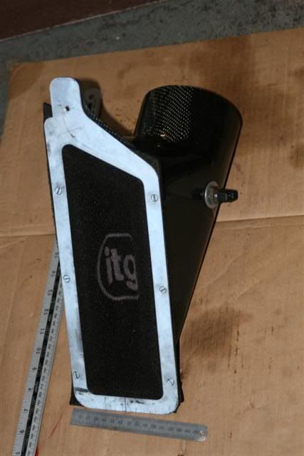
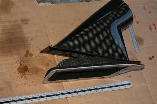
Excellent write up BTW, well impressed with your skills buddy.
Give them a call. They've made a couple now including mine.
Here's a couple of pictures:
Excellent write up BTW, well impressed with your skills buddy.

1988 Diamond Schwartz E30 M3
^ fanny, I didn't know that and I've gone a different route. Thanks for the
tip though may end up going that way in the end.
tip though may end up going that way in the end.
Well, it's taken what feels like an absolute eternity to get to this stage of the build,
but, finally, the engine is ready to be reunited with the chassis........


there was a few little things to take care of before the engine could be lowered
into the bay. Once the engine was off the stand the flywheel and clutch needed
to be refitted. In keeping with the theme of the rest of the engine build I've gone
with a lightweight flywheel. The flywheel weighs in at 5.3kg and is supplied by
http://www.ttvracing.com/BMWS14flywheel.html.......

With the flywheel in place the clutch could then be fitted. The clutch was
only fitted to the car shortly before it came off the road for this little make over,
and as a result has very little mileage on it and is good to go again......

but, finally, the engine is ready to be reunited with the chassis........
there was a few little things to take care of before the engine could be lowered
into the bay. Once the engine was off the stand the flywheel and clutch needed
to be refitted. In keeping with the theme of the rest of the engine build I've gone
with a lightweight flywheel. The flywheel weighs in at 5.3kg and is supplied by
http://www.ttvracing.com/BMWS14flywheel.html.......
With the flywheel in place the clutch could then be fitted. The clutch was
only fitted to the car shortly before it came off the road for this little make over,
and as a result has very little mileage on it and is good to go again......
The clutch disc is sandwiched into place by the pressure plate which is
bolted on by six little bolts, shown below........

the important bit being to make sure the splines in the centre of the clutch disc
line up with that little spigot bearing in the centre of the crankshaft..........

as when you go to throw in the gearbox later on, the splines on the
input shaft (red arrow) need to slot into the splines on the clutch disc,
and the little piece on the end of the input shaft (yellow arrow) needs
to slot home into the centre of the crank spigot bearing..........

So you can see it's worth spending a few minutes now to make sure the clutch
disc is lined up correctly, rather than busting a ball later trying to fit the gearbox into
place when things don't line up. If you find yourself in the same position I do,
with both engine and gearbox out of the car, it can make sense to mate the two
of them together outside of the car briefly just to make sure things line up.
With the clutch fitted the final item to go on before the engine is lowered into place
is the gearbox bellhousing.......

(picture borrowed from google images)
As the bellhousing is detachable from the getrag gearbox it can be a lot handier
fitting this to the engine now while it's out of the car, and then when everythings
back in the car you've 4 nice studs sitting out the back of the bellhousing to
lift the gearbox onto, rather than fumbling around trying to get bellhousing to
engine bolts started.
With all the soundproofing and heat sheilds fitted to the engine bay the
way was now clear to shove it back in.....

And then with a wave of the magic wand and quite a bit of foul language
the engine and gearbox magically find their way home.........


(click on the image below for a full size view)

more to follow as the week goes on.........
bolted on by six little bolts, shown below........
the important bit being to make sure the splines in the centre of the clutch disc
line up with that little spigot bearing in the centre of the crankshaft..........
as when you go to throw in the gearbox later on, the splines on the
input shaft (red arrow) need to slot into the splines on the clutch disc,
and the little piece on the end of the input shaft (yellow arrow) needs
to slot home into the centre of the crank spigot bearing..........
So you can see it's worth spending a few minutes now to make sure the clutch
disc is lined up correctly, rather than busting a ball later trying to fit the gearbox into
place when things don't line up. If you find yourself in the same position I do,
with both engine and gearbox out of the car, it can make sense to mate the two
of them together outside of the car briefly just to make sure things line up.
With the clutch fitted the final item to go on before the engine is lowered into place
is the gearbox bellhousing.......
(picture borrowed from google images)
As the bellhousing is detachable from the getrag gearbox it can be a lot handier
fitting this to the engine now while it's out of the car, and then when everythings
back in the car you've 4 nice studs sitting out the back of the bellhousing to
lift the gearbox onto, rather than fumbling around trying to get bellhousing to
engine bolts started.
With all the soundproofing and heat sheilds fitted to the engine bay the
way was now clear to shove it back in.....
And then with a wave of the magic wand and quite a bit of foul language
the engine and gearbox magically find their way home.........
(click on the image below for a full size view)
more to follow as the week goes on.........
-
goosiegander
- Zonegoose
- Posts: 2544
- Joined: Sun Nov 19, 2006 11:00 pm
- Location: East Anglia
Fooking Awesome! 


This is the 'tickly bit' folks......awesome....
Phase I - Bodywork Complete
http://www.e30zone.net/modules.php?name ... by+restore
Phase II - 2.8 stroker- Complete
Project II - 325 Motorsport Cabriolet Restoration.
http://www.e30zone.net/modules.php?name ... by+restore
Phase II - 2.8 stroker- Complete
Project II - 325 Motorsport Cabriolet Restoration.
nice one x-works, you must be chuffed the engines finally back in
With the engine now back in place focus could turn to some of the item's that
would need relocation thanks to the bulky addition of that new airbox.
First on the list was the brake fluid reservoir..........

With the new airbox proudly now sitting in the space where the old reservoir
pictured above used to be, a plan needed to be hatched.
Common wisdom suggests that a good sized hammer can almost always make
two objects occupy the same space at the same time, however, since the airbox
"kit" I had purchased came with the bits to relocate reservoir, I decided to
save the hammer approach as "Plan B".
Below is a picture of the reservoir that came with the kit.......

theres absolutely nothing wrong with it and I'm sure it works fine, for reasons
still unknown to me I decided to endure a lot more hardship to make the
reservoir below work instead.........

The one slightly large difference between the two reservoirs above is the
"kit" one has the required 3 outlets (2 x brake master cylinder feeds, 1 x clutch master
cylinder feed) and the one I had decided to use had a big, useless, threaded lump
of an outlet.
So, the threaded fitting was removed for the reservoir and an hours worth of beating,
drilling and brazing had it looking a bit more functional........

After which it was a simple matter of fitting the two supplied elbows to
the master cylinder.......

and then connecting everything up with the correct spec. hose.......

What the above picture doesn't show to well is the feed from the reservoir
down to the clutch master cylinder, which travels down behind the brake servo.
I had actually taken a separate picture of this, but, due to my continuing startling
incompetence with a camera, it came out pitch black.
Gifted.
One thing probably worth mentioning before we move on is about the
hose used to carry the brake fluid. I can't remember the part number for the
Gates hosing used here,( it's late and if I go searching the net for it I'll just get
distracted by porn sites or cheap shiney shite on e-bay), but if you find yourself
doing a similar job it's worth spending a few minutes checking the manufacturers
website to see if it's compatible with the type of brake fluid you intend to use.
Some hoses have difficulty containing synthetic brake fluid and will slowly weep
it all out over your nice clean engine bay. Which is fun.
With the reservoir plumbed up all that was left was the small matter of mounting
it somewhere. Small bit of stainless steel cut and bent to the correct shape..........

and a few holes drilled and taped into the underside of the strut brace......


bingo......


more tomorrow.........
would need relocation thanks to the bulky addition of that new airbox.
First on the list was the brake fluid reservoir..........
With the new airbox proudly now sitting in the space where the old reservoir
pictured above used to be, a plan needed to be hatched.
Common wisdom suggests that a good sized hammer can almost always make
two objects occupy the same space at the same time, however, since the airbox
"kit" I had purchased came with the bits to relocate reservoir, I decided to
save the hammer approach as "Plan B".
Below is a picture of the reservoir that came with the kit.......
theres absolutely nothing wrong with it and I'm sure it works fine, for reasons
still unknown to me I decided to endure a lot more hardship to make the
reservoir below work instead.........
The one slightly large difference between the two reservoirs above is the
"kit" one has the required 3 outlets (2 x brake master cylinder feeds, 1 x clutch master
cylinder feed) and the one I had decided to use had a big, useless, threaded lump
of an outlet.
So, the threaded fitting was removed for the reservoir and an hours worth of beating,
drilling and brazing had it looking a bit more functional........
After which it was a simple matter of fitting the two supplied elbows to
the master cylinder.......
and then connecting everything up with the correct spec. hose.......
What the above picture doesn't show to well is the feed from the reservoir
down to the clutch master cylinder, which travels down behind the brake servo.
I had actually taken a separate picture of this, but, due to my continuing startling
incompetence with a camera, it came out pitch black.
Gifted.
One thing probably worth mentioning before we move on is about the
hose used to carry the brake fluid. I can't remember the part number for the
Gates hosing used here,( it's late and if I go searching the net for it I'll just get
distracted by porn sites or cheap shiney shite on e-bay), but if you find yourself
doing a similar job it's worth spending a few minutes checking the manufacturers
website to see if it's compatible with the type of brake fluid you intend to use.
Some hoses have difficulty containing synthetic brake fluid and will slowly weep
it all out over your nice clean engine bay. Which is fun.
With the reservoir plumbed up all that was left was the small matter of mounting
it somewhere. Small bit of stainless steel cut and bent to the correct shape..........
and a few holes drilled and taped into the underside of the strut brace......
bingo......
more tomorrow.........
-
bmwe30mtech
- Engaged to the E30 Zone

- Posts: 5288
- Joined: Thu Feb 03, 2005 11:00 pm
Fantastic work, good reading.
Out of interest, why didn't you attach the whole box to the engine and drop it in as one lump? Would this not be easier than bolting the box to the bell housing in situ? I only ask because I'm about to do this! Thanks
Out of interest, why didn't you attach the whole box to the engine and drop it in as one lump? Would this not be easier than bolting the box to the bell housing in situ? I only ask because I'm about to do this! Thanks
1988 M3 EvoII, Macau Blue/EvoII trim
1989 325i Sport M Tech II, Diamond Black/Black leather
1989 325i Sport M Tech II, Diamond Black/Black leather
I'd imagine it probably can be done that way, but the exhaust manifold kinda needs to
go in bolted to the engine as it's an awkward b*stard to get in afterwards. This and the
bellhousing being attached to the block makes it just about manageable while dropping
it into a freshly painted engine bay without battering it off something.
Afterwards it's fairly handy to lift the gearbox up into place thanks to the pit.
If I was doing it with the car on axle stands on flat ground I'd definitely stick the
whole lot in together from the top.

I always put the engine in first then the gear box after. On a ramp or on axle stands.bmwe30mtech wrote:Fantastic work, good reading.
Out of interest, why didn't you attach the whole box to the engine and drop it in as one lump? Would this not be easier than bolting the box to the bell housing in situ? I only ask because I'm about to do this! Thanks
Long extensions to reach the top bell housing bolts.
-
bmwe30mtech
- Engaged to the E30 Zone
- Posts: 5288
- Joined: Thu Feb 03, 2005 11:00 pm
Thanks for the responses. I have no ramp for my current build so will drop it all in as one and try not to scrape the paint.
One other question, when you re-build the TB's, did you remove the flaps inside them? If so, how, because the little philips head screws holding them to the shalf seem to be flared at the end of the thread, so they cannot be undone. Am I missing something?
One other question, when you re-build the TB's, did you remove the flaps inside them? If so, how, because the little philips head screws holding them to the shalf seem to be flared at the end of the thread, so they cannot be undone. Am I missing something?
1988 M3 EvoII, Macau Blue/EvoII trim
1989 325i Sport M Tech II, Diamond Black/Black leather
1989 325i Sport M Tech II, Diamond Black/Black leather
Nope, your bang on the money. The little screws are riveted over on the back side
to prevent them ever falling out i'd imagine. You can, very carefully, buff this end
off with a Dremel which should allow the screws to be then screwed out, but it is
very easy to strip the threads on the butterfly shaft if you get it wrong. Personally
I only remove the butterflies if they really need to come out as you need new screws
going back and they can be a pig to re-rivet again.
The other thing to watch out for is when your removing the little levers on the end
of the butterfly shafts. They can be tight and it can be tempting to wedge a little flat
screwdriver between the lever and the throttle body to help ease them off.
As the shaft can float side to side in the throttle body what usually happens then is
the butterfly digs into the soft inner wall inside as your prying at the lever outside,
resulting in grooves that the butterfly can catch on when everything is back together.
-
bmwe30mtech
- Engaged to the E30 Zone
- Posts: 5288
- Joined: Thu Feb 03, 2005 11:00 pm
Ahh, that makes sense now, thanks. I haven't seen screws with the ends riveted like that before, makes sense as it could be catastrophic if it flew into the engine. The shaft which the butterflys sit on is quite tight in the TB housing, meaning it does not return properly. Based on your advice though I will try and lube it up in situ.
Thanks for the heads up with taking the levers off, I did one this evening and it was very tight, glad I didn't force it much now!
Thanks for the heads up with taking the levers off, I did one this evening and it was very tight, glad I didn't force it much now!
1988 M3 EvoII, Macau Blue/EvoII trim
1989 325i Sport M Tech II, Diamond Black/Black leather
1989 325i Sport M Tech II, Diamond Black/Black leather
Next on the list of things needing to find a new home was the power steering reservoir.
Like all e30's it's normally bolted to the turret, however with the addition of the new
airbox this is no longer possible.
The new site was to be a little lower down on the front inner valence using these two
original studs for mounting............

the original reservoir mounting bracket needed a little modifying before it was
good to go again. With the spot welds drilled the mounting part could be removed
and tossed........

to be replaced with this instead........

once welded on the bracket was bolted up to check I hadn't welded it arseways,
which seems to happen with alarming regularity.......

all good, so a quick lick of paint........

and nail her on for good..........

There was one other slight mod done to the steering system and it was
carried out a while back when the driveline was going in and that was
to change the steering rack.
If your the kind of person that likes to let the car steer from the rear every
now and then, more than likely you'll have noticed how slow the steering
is on e30's. A fairly common "upgrade" is to fit a quicker ratio steering rack
from some of the more modern BMW's and this is what I've chosen to do.
However, sourcing the correct left hand drive rack in a country full of right
hand drive cars proved fairly challenging. Thankfully a good friend came to
the rescue with what you see below, a reconditioned E46 compact steering rack,
I think.......

the reason I say "I think" is because there's no BMW or ZF identification numbers left on
the rack after it was reconditioned. Nothing too suspicious in this, I've bought a few
reconed racks in the past from TRW and they were all the same.
However it does leave you with a little bit of a conundrum. How do you know if
this rack is going to be any faster than the one already in the car?
The answer is fairly straight forward, measure the movement.
With the rack on the bench like below one of the dust boots is removed
from either side and then by turning the input shaft lock the steering all the way to
one side.
Then, turn the input shaft exactly 1 complete turn in the opposite direction and
measure how much the rack moves.........

The standard steering rack in an e30 M3 moves the rack 38mm for one
complete turn of the input shaft. So any more than this is going to give you
a quicker steering rack. As you can see above this rack moves 50mm for
one turn which is quite a bit "quicker" than the old one.
The only other rack I've ever had the chance to measure was the rack
from a Z3 BMW which is a popular choice, and it measured 53mm,
which I think maybe the quickest BMW rack that will fit an e30.
So, happy that the rack I had was going to quicken up the steering response
the next job was to get it ready to bolt in. The first thing that needed to be done
was to swap out the inner track rod arms, as the ones that came fitted to the new
rack where the male threaded variety, whereas I wanted to retain the e30's
female threaded ones............

Like all e30's it's normally bolted to the turret, however with the addition of the new
airbox this is no longer possible.
The new site was to be a little lower down on the front inner valence using these two
original studs for mounting............
the original reservoir mounting bracket needed a little modifying before it was
good to go again. With the spot welds drilled the mounting part could be removed
and tossed........
to be replaced with this instead........
once welded on the bracket was bolted up to check I hadn't welded it arseways,
which seems to happen with alarming regularity.......
all good, so a quick lick of paint........
and nail her on for good..........
There was one other slight mod done to the steering system and it was
carried out a while back when the driveline was going in and that was
to change the steering rack.
If your the kind of person that likes to let the car steer from the rear every
now and then, more than likely you'll have noticed how slow the steering
is on e30's. A fairly common "upgrade" is to fit a quicker ratio steering rack
from some of the more modern BMW's and this is what I've chosen to do.
However, sourcing the correct left hand drive rack in a country full of right
hand drive cars proved fairly challenging. Thankfully a good friend came to
the rescue with what you see below, a reconditioned E46 compact steering rack,
I think.......
the reason I say "I think" is because there's no BMW or ZF identification numbers left on
the rack after it was reconditioned. Nothing too suspicious in this, I've bought a few
reconed racks in the past from TRW and they were all the same.
However it does leave you with a little bit of a conundrum. How do you know if
this rack is going to be any faster than the one already in the car?
The answer is fairly straight forward, measure the movement.
With the rack on the bench like below one of the dust boots is removed
from either side and then by turning the input shaft lock the steering all the way to
one side.
Then, turn the input shaft exactly 1 complete turn in the opposite direction and
measure how much the rack moves.........
The standard steering rack in an e30 M3 moves the rack 38mm for one
complete turn of the input shaft. So any more than this is going to give you
a quicker steering rack. As you can see above this rack moves 50mm for
one turn which is quite a bit "quicker" than the old one.
The only other rack I've ever had the chance to measure was the rack
from a Z3 BMW which is a popular choice, and it measured 53mm,
which I think maybe the quickest BMW rack that will fit an e30.
So, happy that the rack I had was going to quicken up the steering response
the next job was to get it ready to bolt in. The first thing that needed to be done
was to swap out the inner track rod arms, as the ones that came fitted to the new
rack where the male threaded variety, whereas I wanted to retain the e30's
female threaded ones............

The ball joints of my original inner track rods were still in perfect
nick so a quick clean up, a lick of paint and some fresh grease in on
the ball joints and they were ready to go again.........


When these inner track rods were fitted to the e30 steering rack they
had a little washer with two bendable tabs to prevent them ever unscrewing,
however these washers aren't compatible with the new rack, so instead
they're getting a dab of loctite to keep them secure........


The last things that were needed to complete the rack were the outer track rods ends.
The balljoints on the old ones were showing signs of wear so a fresh pair took
their place..........

With everything buttoned up the rack was now ready to bolt into the subframe.......

To do this requires a pair of little spacers as the mounting tabs on the new rack
come up a little short between the mounting lugs that hold it on the subframe.........

for now a little pair of spacers 13.5mm high were made up to go between the
top of the rack mounts and under the subframe lug as shown by the arrow above.
The height and number of spacers may change a little down the line when we get around
to measuring front suspension bump steer, but for today those 13.5mm one's will do fine.
Final piece of the jigsaw is the steering shaft. The original was cleaned up,
fitted with a new rubber guibo and is good to go again with no noticeable
wear in the joints........

the splines at either end get a wee dab of grease so you don't need to
swing the hammer quite as far when battering them into place.......

-
shedrool83
- Old Skooler

- Posts: 4395
- Joined: Thu May 10, 2007 11:00 pm
- Location: Dundee Scotland
Epic stuff

now the tricky bit. The pinion shaft on the new rack sits a little bit
taller than the old one and the result of this is you have to slide the
splined end of the steering shaft a little further down onto it to get
everything to fit in place........

The end result of this is, when fitted, the hole in the steering shaft coupling
for the pinch bolt to slide though now doesn't line up with that groove
(it has slid down a little bit past it).........

It's not the end of the world however, as the bolt will still fit in fine and
do it's job, it just needs to be screwed in now rather than simply falling in as before.
The one thing this is mucho importante is that the splines don't protrude to much
up into the coupling and start to interfere with the free rotation of the upper part
of the joint.........

To help with this I loosened the coupling at both ends of the steering shaft
and made sure the same amount of splines were protruding both ends,
rather than trying to do it all one end.........

With everything nipped up tight the steering gets a few locks from side
to side while checking theres no fouling going on and everythings as smooth
as it was the day it left the factory. However much of a pain in the arse it is
to have to deal with problems now, there's a good chance it would be pain all over
if you start finding problems while thrashing down a country lane.
With the rack, pump and reservoir now in place all that was left was the hydraulic
pipes that join them all together........

The original M3 pipes are all good to go again with one small tweek.
The low pressure pipes are good to go as is, as being made of rubber
they easily flex to their new locations. The high pressure pipe however
needs a little bit of modifying to match up with the slightly different
angle of the new steering racks inlet port.......

The "tweek" isn't too complicated, it is however a little hard to photograph.
Basically the steel end of the pressure pipe needs to be bent a little to
open up the angle on the pipe as shown below. There's two ways to bend the
pipe, slowly and gently in the vise, or, quickly and roughly and the resulting
call to the main dealer to price a new one..........

The bend shown above is to steer the pipe clear of the engine block
and engine mounting leg when it's fitted.......

theres one other slight bend needed and thats to take the pipe away from the
steering knuckle.......

although it doesn't look it above due to the crap angle I decided to take
a photo at, theres a good half inch clearance between the pipe and the knuckle.
And thats about all that was involved in getting the steering system sorted.
More as the week goes on..........
taller than the old one and the result of this is you have to slide the
splined end of the steering shaft a little further down onto it to get
everything to fit in place........
The end result of this is, when fitted, the hole in the steering shaft coupling
for the pinch bolt to slide though now doesn't line up with that groove
(it has slid down a little bit past it).........
It's not the end of the world however, as the bolt will still fit in fine and
do it's job, it just needs to be screwed in now rather than simply falling in as before.
The one thing this is mucho importante is that the splines don't protrude to much
up into the coupling and start to interfere with the free rotation of the upper part
of the joint.........
To help with this I loosened the coupling at both ends of the steering shaft
and made sure the same amount of splines were protruding both ends,
rather than trying to do it all one end.........
With everything nipped up tight the steering gets a few locks from side
to side while checking theres no fouling going on and everythings as smooth
as it was the day it left the factory. However much of a pain in the arse it is
to have to deal with problems now, there's a good chance it would be pain all over
if you start finding problems while thrashing down a country lane.
With the rack, pump and reservoir now in place all that was left was the hydraulic
pipes that join them all together........
The original M3 pipes are all good to go again with one small tweek.
The low pressure pipes are good to go as is, as being made of rubber
they easily flex to their new locations. The high pressure pipe however
needs a little bit of modifying to match up with the slightly different
angle of the new steering racks inlet port.......
The "tweek" isn't too complicated, it is however a little hard to photograph.
Basically the steel end of the pressure pipe needs to be bent a little to
open up the angle on the pipe as shown below. There's two ways to bend the
pipe, slowly and gently in the vise, or, quickly and roughly and the resulting
call to the main dealer to price a new one..........
The bend shown above is to steer the pipe clear of the engine block
and engine mounting leg when it's fitted.......
theres one other slight bend needed and thats to take the pipe away from the
steering knuckle.......
although it doesn't look it above due to the crap angle I decided to take
a photo at, theres a good half inch clearance between the pipe and the knuckle.
And thats about all that was involved in getting the steering system sorted.
More as the week goes on..........
-
dn808e2
- E30 Zone Regular

- Posts: 499
- Joined: Sat Mar 11, 2006 11:00 pm
- Location: Kings lynn, Norfolk.
To xworks , from the exhaust side of the engine is wery little space between exhaust manifold and the chassy , so when the engine will run the exhaust will eventially over heat that aerea , please get metal plate and cut to rigt size and slot it between manifold and the pannel when suspention leg is seats in , sorry for bad english
i'll make a pic of mine plate and show it to u , but u must do it or otherwise i'll destroy the paint very soon.
http://tynipic.com/viewer.php?id=viu1316938943m.JPG
http://tynipic.com/images/rgh1316938841j.JPG
http://tynipic.com/images/bfi1316938880b.JPG
i'll make a pic of mine plate and show it to u , but u must do it or otherwise i'll destroy the paint very soon.
http://tynipic.com/viewer.php?id=viu1316938943m.JPG
http://tynipic.com/images/rgh1316938841j.JPG
http://tynipic.com/images/bfi1316938880b.JPG
^ cheers mate, will give it a try.
Theres a good few bits and pieces of stuff getting bolted on around the car at this
stage of the rebuild and a large number of them attach to the shell with the
aid of screws and spire clips.......

I'm not a huge fan of spire clips and where ever possible I try to use rivet nuts instead.......

as due to their design they they don't trap moisture against the bodywork
like spire clips can and hopefully should keep the rust at bay a little
while longer..........

The front crossmember gets a pair of them to mount the engine oil cooler............


With the cooler and hoses mounted it can be prefilled with fresh
oil before the fittings are screwed back home onto the filter housing.
This can take an age to do thanks to the smallish bore of the hose and
the stubborn thickness of cold engine oil, but your engine will thank you
for it on that first start up........

Another little puzzle that needed sorting was to do with the front wheel
arch plastic liners. The liners are held in place up under the wings with a few
screws and plastic nuts at various places. One of those places was in the little
"jacking box" at the bottom of the wheel arch.
I had a wee problem here.......

back at the start of the bodywork repairs these were consigned to the bin.
D'oh.
The solution I went with was a little pair of stainless steel brackets with
rivet nuts attached.........

one to be bonded to each side of the floor pan where the "jacking boxes"
used to be, to provide a new mounting point for the wheel arch liner bottom screw.......


Next on the agenda was the radiator fan......

A while before coming off the road for this little "freshen up" I had a fair bit of
bother with the fan on this car. Sometimes she'd work, sometimes she wouldn't.
I'd been through all the normal fixes to no avail, (fan resistor, fan switch, fan switch
wiring) which left me with the impression that something inside the fan motor itself
was starting to intermittently fail.
There's very few things in life as sure to frustrate your driving experience as always having
to keep an eye on the temperature gauge while in heavy traffic, wondering if today's the day
the fan will totally fail and transform your engine into an expensive kettle.
According to the service literature the original fan is a "non serviceable part" which
"cannot be dismantled and repaired".
Nonsense, it's a plastic bloody fan with a 12 volt motor jammed in the middle
it's not nuclear physics. So, out with the hammer.........

Very shortly after this I decided an after market fan would be a nice upgrade,
can't remember exactly why I came to this decision, but best we move on quickly.
A quick search of the interweb threw up this baby.........

A 16 inch Spal pusher fan (VA18-AP71/LL-42S) with curved blades
to keep the noise down a little.......

I couldn't find any info on how much cubic feet of air the original Bmw fan shifted
to help choose the correct size Spal fan, so, I just did what any logical thinking red blooded
male would do, ordered the biggest fan in the catalogue.
This seemed like a great idea right up until the fan arrived, I removed it from it's
packaging, marvelled briefly at it's enormity and offered it up to the front of the
radiator.
F*ck, f*ck, fuckidy f*ck.
It wouldn't fit.
After a short recess to allow blood pressure to return to normal levels it became
clear that the fan could be made to fit if the front crossmember was trimmed down
a little (red section)........

stage of the rebuild and a large number of them attach to the shell with the
aid of screws and spire clips.......
I'm not a huge fan of spire clips and where ever possible I try to use rivet nuts instead.......
as due to their design they they don't trap moisture against the bodywork
like spire clips can and hopefully should keep the rust at bay a little
while longer..........
The front crossmember gets a pair of them to mount the engine oil cooler............
With the cooler and hoses mounted it can be prefilled with fresh
oil before the fittings are screwed back home onto the filter housing.
This can take an age to do thanks to the smallish bore of the hose and
the stubborn thickness of cold engine oil, but your engine will thank you
for it on that first start up........
Another little puzzle that needed sorting was to do with the front wheel
arch plastic liners. The liners are held in place up under the wings with a few
screws and plastic nuts at various places. One of those places was in the little
"jacking box" at the bottom of the wheel arch.
I had a wee problem here.......
back at the start of the bodywork repairs these were consigned to the bin.
D'oh.
The solution I went with was a little pair of stainless steel brackets with
rivet nuts attached.........
one to be bonded to each side of the floor pan where the "jacking boxes"
used to be, to provide a new mounting point for the wheel arch liner bottom screw.......
Next on the agenda was the radiator fan......
A while before coming off the road for this little "freshen up" I had a fair bit of
bother with the fan on this car. Sometimes she'd work, sometimes she wouldn't.
I'd been through all the normal fixes to no avail, (fan resistor, fan switch, fan switch
wiring) which left me with the impression that something inside the fan motor itself
was starting to intermittently fail.
There's very few things in life as sure to frustrate your driving experience as always having
to keep an eye on the temperature gauge while in heavy traffic, wondering if today's the day
the fan will totally fail and transform your engine into an expensive kettle.
According to the service literature the original fan is a "non serviceable part" which
"cannot be dismantled and repaired".
Nonsense, it's a plastic bloody fan with a 12 volt motor jammed in the middle
it's not nuclear physics. So, out with the hammer.........
Very shortly after this I decided an after market fan would be a nice upgrade,
can't remember exactly why I came to this decision, but best we move on quickly.
A quick search of the interweb threw up this baby.........
A 16 inch Spal pusher fan (VA18-AP71/LL-42S) with curved blades
to keep the noise down a little.......
I couldn't find any info on how much cubic feet of air the original Bmw fan shifted
to help choose the correct size Spal fan, so, I just did what any logical thinking red blooded
male would do, ordered the biggest fan in the catalogue.
This seemed like a great idea right up until the fan arrived, I removed it from it's
packaging, marvelled briefly at it's enormity and offered it up to the front of the
radiator.
F*ck, f*ck, fuckidy f*ck.
It wouldn't fit.
After a short recess to allow blood pressure to return to normal levels it became
clear that the fan could be made to fit if the front crossmember was trimmed down
a little (red section)........
So, happy that the fan could actually be made to fit the next thing to
sort was mounting it. The original fan was mounted to the bodywork
but I've decided to mount the new one directly to the radiator itself.......

Some templates drawn up for the pair of mounting brackets to be used
and then transferred to aluminium...........

using the usual selection of cutting edge modern technology.......

meant that it required numerous hours of ballache to transform this.......

into these.........

after which some spacers were added to the brackets to avoid
the fan munching it's way through the radiator core.........

before finally getting a splatter of black paint.........

bolt them up to the fan..........

and then with the aid of some tubular aluminium pipe spacers, bolt the
brackets to the radiator.........


which ends up looking like so............

and when fitted..........


I'm confident if this car overheats in traffic in the future it'll be because it's sucked a passing
cyclist through the grill.
more as the week goes on............
sort was mounting it. The original fan was mounted to the bodywork
but I've decided to mount the new one directly to the radiator itself.......
Some templates drawn up for the pair of mounting brackets to be used
and then transferred to aluminium...........
using the usual selection of cutting edge modern technology.......
meant that it required numerous hours of ballache to transform this.......
into these.........
after which some spacers were added to the brackets to avoid
the fan munching it's way through the radiator core.........
before finally getting a splatter of black paint.........
bolt them up to the fan..........
and then with the aid of some tubular aluminium pipe spacers, bolt the
brackets to the radiator.........
which ends up looking like so............
and when fitted..........
I'm confident if this car overheats in traffic in the future it'll be because it's sucked a passing
cyclist through the grill.
more as the week goes on............
-
cool_ram_in
- E30 Zone Newbie

- Posts: 87
- Joined: Mon Jun 23, 2008 11:00 pm
Very detailed build! It also covers almost every bit of the car!
Thank you for your patience to educate us mortals!
I will keep an eye overhere!
Thank you for your patience to educate us mortals!
I will keep an eye overhere!
-
goosiegander
- Zonegoose
- Posts: 2544
- Joined: Sun Nov 19, 2006 11:00 pm
- Location: East Anglia
Given the detail of this build would it be worth replacing the Abs sensor plugs in the bay?
I presume they are white and discolour in the bay's environment either by oil, grime or factory laquer...
Still awesome,

I presume they are white and discolour in the bay's environment either by oil, grime or factory laquer...
Still awesome,
-
gnarkillius

- E30 Zone Newbie
- Posts: 234
- Joined: Sun Dec 09, 2007 11:00 pm
- Location: Pompey/Manchester
What a thread. Im commenting to subscribe!
Great detail, great writeup.
Thanks for doing this mate, seriously motivates people to 'get mine done'.
*wanders off to do a midnight session on the stupid keyless opening/immobilser on mine
I might even do a mini thread on that, inspired by your epic. Mine will be more a comedy thread, of a fellow scratching his head over a solenoid and door card removal, but hey, not everyone can be UBERMENSCH
goosiegander wrote:Given the detail of this build would it be worth replacing the Abs sensor plugs in the bay?

Chapter 146
How, in the name of all thats holy, is this car not finished yet?
Starting this evenings episode off with a little revision of a job that was previously signed
off on and thought finished. The item in question? The brake/clutch fluid reservoir.
You may remember from an earlier post that I had gone with a universal fluid reservoir
and made a little fitting to give it the three feeds out it needed................
Well it's been pointed out to me that mightn't have been the best way to go. Unlike the
reservoir pictured above the one that was actually supplied with the airbox kit (shown below)
has one large advantage, a little plastic chamber divider inside the pot. It's purpose?
Should you happen develop a leak in any of the three circuits the reservoir feeds
(clutch / front brakes / rear brakes) the little plastic divider ensures there is enough
fluid retained to ensure at least one brake circuit remains functional...........

I had originally thought this was covered with the old design, but, when I opened a few
bleed nipples here and there to simulate leaks what actually happened was the leaking circuit
could actually syphon fluid from the good circuits to leave everything f*cked.
Takes true genius to come up with that sort of design.
Anywho, the results of a few hours head scratching came up with the following as
a method of mounting the proper reservoir and manage to avoid the strut brace
which seemed determined to get in the way.
The little mounting tab which was cut off the power steering reservoir bracket earlier
was recalled to active duty.........

and once welded to a few other bits of shaped metal it was to form the basis
of the new brake reservoir mounting bracket..........


bit of filing, sanding, hammering and a lick of paint to get it presentable.......

and bolt her up........


As God as my witness, if this one gives any trouble the whole lot's gettin ripped out
and I'm weldin a compressor onto the engine block and running a bloody air brake system instead.
How, in the name of all thats holy, is this car not finished yet?
Starting this evenings episode off with a little revision of a job that was previously signed
off on and thought finished. The item in question? The brake/clutch fluid reservoir.
You may remember from an earlier post that I had gone with a universal fluid reservoir
and made a little fitting to give it the three feeds out it needed................
Well it's been pointed out to me that mightn't have been the best way to go. Unlike the
reservoir pictured above the one that was actually supplied with the airbox kit (shown below)
has one large advantage, a little plastic chamber divider inside the pot. It's purpose?
Should you happen develop a leak in any of the three circuits the reservoir feeds
(clutch / front brakes / rear brakes) the little plastic divider ensures there is enough
fluid retained to ensure at least one brake circuit remains functional...........
I had originally thought this was covered with the old design, but, when I opened a few
bleed nipples here and there to simulate leaks what actually happened was the leaking circuit
could actually syphon fluid from the good circuits to leave everything f*cked.
Takes true genius to come up with that sort of design.
Anywho, the results of a few hours head scratching came up with the following as
a method of mounting the proper reservoir and manage to avoid the strut brace
which seemed determined to get in the way.
The little mounting tab which was cut off the power steering reservoir bracket earlier
was recalled to active duty.........
and once welded to a few other bits of shaped metal it was to form the basis
of the new brake reservoir mounting bracket..........
bit of filing, sanding, hammering and a lick of paint to get it presentable.......
and bolt her up........
As God as my witness, if this one gives any trouble the whole lot's gettin ripped out
and I'm weldin a compressor onto the engine block and running a bloody air brake system instead.
-
THE_GODFATHER
- E30 Zone Newbie
- Posts: 199
- Joined: Fri Apr 25, 2008 11:00 pm
One of the best projects on the zone 