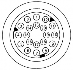
C101
The C101 plug is the biggest connector on the vehicle Loom. It allows the entire engine wiring to be disconnected from the rest of the vehicle, so that the engine can be removed easily. It is located on the bulkhead in the engine bay, next to the brake servo.
All of the wiring that passes through the C101 is a key part of the Engine Management.
There were two versions of the C101 plug fitted. The "round" style fitted to Motronic vehicles, and the "square" style fitted to Jetronic vehicles.
Motronic
| Pin | Colour | Function | To | Image |
|---|---|---|---|---|
| 1 | Blue | Charge light | pin 16 blue plug inst cluster | 
|
| 2 | Green/Yellow | Static oil level | Pin 16 check panel | |
| 3 | ||||
| 4 | Brown/Purple | Temp gauge | pin 26 blue plug inst cluster | |
| 5 | Brown/Green | Oil Pressure light | pin 18 blue plug inst cluster | |
| 6 | Green/White | Oxygen sensor relay | Fuse 9 | |
| 7 | Green | Switched power | Ignition switch | |
| 8 | White/Black | Fuel rate input | pin 11 blue plug inst cluster | |
| 9 | Black | Engine speed input | pin 7 blue plug inst cluster | |
| 10 | Blue | Dynamic Oil level | pin 20 Check Panel | |
| 11 | White/Green | Reset service lights | pin 22 blue plug inst cluster | |
| 12 | Grey | Check Engine indicator | Check Light | |
| 13 | Green/Purple | fuel pump relay | fuse 11 | |
| 14 | Black/White | Speed signal out to ECU | pin 10 white plug inst cluster | |
| 15 | Black/Green | Unloader relay | pin 1 blue plug inst cluster | |
| 16 | White/Black | Diagnostic connector | Diagnostic plug pin 6 | |
| 17 | ||||
| 18 | Black/Yellow | Start | Ignition switch | |
| 19 | ||||
| 20 | Red/Yellow | ABS power | ABS control module | |
WARNING: There is one difference in the C101 design between the E30s, and that is Pin 20. On early vehicles, Pin 20 is a brown earth wire, while for some later vehicles Pin 20 is a live, unfused red/yellow wire for the ABS system. If you are changing your engine, CHECK PIN 20 ON BOTH SIDES OF THE C101 PLUG before connecting the battery.
If you have a brown wire connected, cut it away from the pin, and make sure the free end can't come into contact with anything. If it is red/yellow, then leave it alone. Of course, if the body side of your C101 has a red/yellow wire on pin 20, and your new engine loom has nothing connected to this pin, you need to add a wire, capable of carrying about 15A, from either of the terminals marked '87' on the DME relay socket to pin 20 of the the C101 plug, otherwise your ABS braking system won't work.
Jetronic
| Pin | Colour | Function | To | Image |
|---|---|---|---|---|
| 1 | Blue | Charge light | pin 16 blue plug inst cluster | 
|
| 2 | Green/Yellow | Static oil level | Pin 16 check panel | |
| 3 | ||||
| 4 | Brown | Temp gauge | pin 26 blue plug inst cluster | |
| 5 | ||||
| 6 | Green/White | Oxygen sensor relay | Fuse 9 | |
| 7 | Green/Purple | fuel pump relay | fuse 11 | |
| 8 | White/Black | Start | Ignition Switch | |
| 9 | ||||
| 10 | Live power from ignition | unfused | ||
| 11 | ||||
| 12 | ||||
| 13 | ||||
| 14 | ||||
| 15 | Black/Green | Unloader relay | pin 1 blue plug inst cluster | |
| 16 | Brown/Green | Oil Pressure light | pin 18 blue plug inst cluster | |
| 17 | White/Green | Reset service lights | pin 22 blue plug inst cluster | |
| 18 | ||||
| 19 | ||||