Steering Rack Conversions
This is more for the UK and Australian (Right hand drive) guys. Probably still valid for the US guys as well.
I have been working on fitting an E36 M3 rack on my 325i Sport. For anyone who read the article on the Zionsville Autosport website (before they decided to sell the info on CD), It is a relatively easy conversion, apart from messing around shortening the Rack to steering column joint.
Zionsville came up with a (not very pretty) solution that I was never all that happy with. I had thought about doing this for a while, but there was no info about doing it to a RHD car. Also, the type of joint that Zionsville modified, is not available in the UK (to my knowledge). Since my engine was already out, I figured now was the time to have a go.
Mounting the rack to the car is basically a straight swap for the E30 rack. You need to use a couple of spacers (approx 14mm) as the mounting points on the E36 rack are not quite as tall as the E30 ones. The spacing of the bolt holes is identical though. You could either make up some spacers, or pack it out with washers. Either would work.
The E36 rod ends bolt straight to the E30 steering arms, so no problem there. You could probably use the E36 power steering pipes with a bit of modification (bending), or have custom pipes made. I chose the latter solution.
Now for the rack to column joint. I think I have found a more elegant and stronger solution (in my opinion) to the Zionsville version.
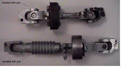
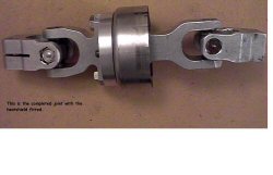
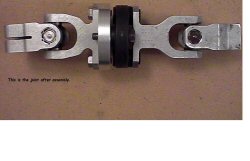
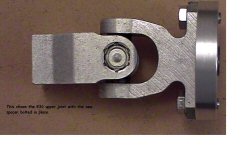
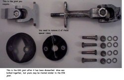
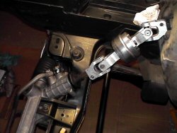
You need to combine the upper UJ from the E30 joint, and the lower UJ from the E36 joint. You also need to make an Aluminium or Steel spacer to join them together. The standard E30 joint is approx 275mm long. This needs to be shortened by 25mm to 250mm long.
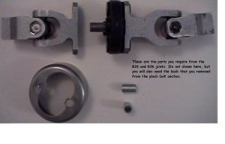
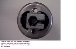
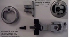
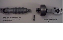
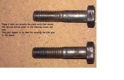
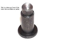
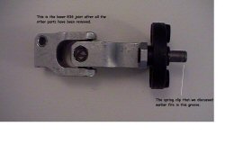
The E36 joint is made in 2 parts. The top half consists of the top UJ and a convoluted portion. This is connected to the lower UJ (and rubber flex joint) by a simple pinch bolt. Remove the bolt and discard the top portion. You now have the lower UJ with the rubber flex joint. You need to drill out the 2 large rivets that hold the pinch bolt section to the flex joint. If you look down the centre of the pinch bolt section, you will also see a small securing clip. Remove this with a small screwdriver. You should now have the lower UJ with the flex joint and 2 empty holes.
On the E30 joint, you need to perform a similar operation. You want just the upper UJ. You may just need to unbolt the existing flex joint if it has previously been replaced. If it is still a 'Virgin', you will need to drill the rivets out.
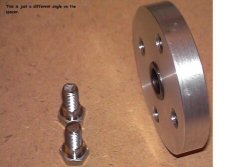
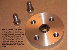
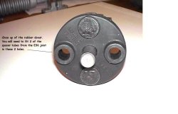
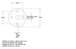
If you offer up the upper E30 joint to the flex joint on the E36 UJ, you will notice that the holes do not align very well. The bolt spacing on the E36 joint is 45mm, and on the E30 it is 50mm. You will also find that the overall length is only 240mm (10mm short). These 2 problems are easily overcome by making a metal (Aluminium or Steel) disc approx 10mm thick with a hole in the centre (I will come back to this hole). You need to drill 2 holes 45mm apart and another 2 holes 50mm apart. These sets of holes need to be offset by 90 degrees. This will allow you to bolt the E30 and E36 UJ's together. The overall length should now be correct. You will need to use 2 of the metal spacer tubes from the E30 flex joint and fit them in the E36 flex joint. You will see what I mean when it is in front of you. The actual thickness of the spacer should be measured on the car to allow for different tolerances between cars and parts etc. 10mm is a rough guide.
Now, back to the hole in the disc. This is for the centering bush (similar to the nylon one on the E30 joint). If you look at the pinch bolt section you removed earlier, you should see a bronze bush in the centre. This is retained by some deformations (stakes ?) in the housing. With some careful drill work, the bush can be removed. It also helps if you cut through the side of the housing and open it up with a chisel. You need to make the hole in the centre of your new metal disc the same as the O/D of the bush. It needs to be a snug fit, and can be retained with some bearing securing solution (Loctite etc).
