
Twin Seq. Dry sumping for beginners :D
Moderator: martauto
-
oakey
- E30 Zone Addict

- Posts: 4891
- Joined: Fri Feb 10, 2006 11:00 pm
- Location: Surrey
Looks mental! absoloutely love it!

-
Turbo-Brown
- Boost Junkie
- Posts: 4705
- Joined: Tue Feb 15, 2005 11:00 pm
- Location: Aldershot, Hants
Crikey, took me a while to get what was going on there but looks like exactly the same system that I'm copying in principal of operation.koos wrote:Pulled a motor on a twin turbo van engine the other day, took some pics, bit of useless info but I thought it sort of related to your monsterIts a Borg-Warner setup, this vans only pushing 150hp but there is no turbo lag, quite nice to drive. Not great pics, with my mobile.
Some very nifty castings being employed there too
Interesting stuff Koos, cheers for posting those piccies
-
koos
- E30 Zone Regular

- Posts: 584
- Joined: Wed Jun 29, 2005 11:00 pm
- Location: Crawley, West Sussex
No prob, they use vacuum transducers to control the wastegates, solenoid controlled by the ECU. Those turbos are quite small aswell. They make a twin turbo 4 cylinder but a single turbo V6? Germans.....
Good luck
Good luck

-
Turbo-Brown
- Boost Junkie
- Posts: 4705
- Joined: Tue Feb 15, 2005 11:00 pm
- Location: Aldershot, Hants
I'm getting more and more worried about how the manufacturer's systems seem to use either a seperate vacuum system or an seperate pressurised air system to take care of all the actuation.
I was hoping to just use boost pressure to move things around as an when necessary.
Certainly that shouldn't be a problem for the two wastegates, and I can't see why it would be for the air valve.......but then why would everyone else use a seperate pneumatic system of some sort?
Hmmmmmmm
I was hoping to just use boost pressure to move things around as an when necessary.
Certainly that shouldn't be a problem for the two wastegates, and I can't see why it would be for the air valve.......but then why would everyone else use a seperate pneumatic system of some sort?
Hmmmmmmm
-
Gunni

- E30 Zone Addict
- Posts: 2115
- Joined: Tue Jan 11, 2005 11:00 pm
- Location: Oxford
Are you going to run boost control via the ems or at least electronically?
I´ve got about a million ideas, but none seem to pan out in the end.
The problem obviously is opening the larger turbo wastegate before it reaches full spool,
-
Gunni
- E30 Zone Addict
- Posts: 2115
- Joined: Tue Jan 11, 2005 11:00 pm
- Location: Oxford
How big can single direction air valves be?
If it would be plumbed into the charge path from the bigger turbo, behind it wouldn´t see any boost
before the large turbo would start boosting and opening the valve, thus you could run the boost line from there to the wastegate to the bigger turbo,
That way the flapper door would be controlled via boost pressure from the manifold or equally the smaller turbo´s charge exit. And the second wastegate would be controlled from the boost pressure from the bigger turbo only??
-
jkarran
- E30 Zone Regular
- Posts: 327
- Joined: Thu Jan 12, 2006 11:00 pm
- Location: Isle of Man
Why not fit a filtered one way valve and a small (1L maybe) reservoir held either at boost pressure or under vacuum to power your wastegates/valve actuators via the ecu/solenoids? That way you have power available all the time even if the manifold isn't under the right pressure/vacuum conditions.
jk
jk
E30 320i Rally Turd - Usually broken
E24 635Csi - Rotting in peace for now
E34 540i - Daily driver
Blown R1 Striker - In progress
E24 635Csi - Rotting in peace for now
E34 540i - Daily driver
Blown R1 Striker - In progress
-
Turbo-Brown
- Boost Junkie
- Posts: 4705
- Joined: Tue Feb 15, 2005 11:00 pm
- Location: Aldershot, Hants
Certainly the small WG can be controlled as a function of both small and large turbo's boost.
And I agree that the large turbo's WG should take it's signal from just the output of the large turbo so the WG can't start opening before it should, and that can be controlled by the ECU's target boost table.
That just leaves the air valve which can't be just blown open by the large turbo as boost on the engine side of the valve will rise at a higher rate than that between the large and small turbos due to boost from the large turbo being multiplied by the small one.
I guess that could take it's signal from down stream of both turbos so it always sees boost, and I can use the second PWM table to control that valve's operation.
I know the BMW system uses vacuum to do the actuation, but the problem I see with this is that the system can only re-charge on the over-run and at idle which, assuming vacuum is lost over time, could lead to inconsistent operation given the differing vac level and possibility of total vacuum loss after hours on the motorway or something.
I had thought of making a little vac pump which could just be driven off the fan belt or something to give a consistent vac supply, although again the level would fluctuate dependent on engine speed.
Whatever happens, I don't wanna get into the realms of closed loop auxiliary position sensing systems! I've had experience of them and know they can be a pain to make work consistently and reliably.
-
Gunni
- E30 Zone Addict
- Posts: 2115
- Joined: Tue Jan 11, 2005 11:00 pm
- Location: Oxford
What air valve?
I´m lost
I´m lost
-
320Touring
- E30 Zone Team Member

- Posts: 12316
- Joined: Fri Feb 11, 2005 11:00 pm
- Location: Glasgow (Scotland)
Didnt know that Aldershot was the porn capital of England...
this is a money shot if I've ever seen one

this is a money shot if I've ever seen one
Turbo-Brown wrote:Yip doo!
More progress this weekend:
The turbos mounted on the tacked together manifold:

The big Unit Parts Clear out Make me an offer on parts!
http://www.e30zone.net/modules.php?name ... 81#2766881
http://www.e30zone.net/modules.php?name ... 81#2766881
-
Turbo-Brown
- Boost Junkie
- Posts: 4705
- Joined: Tue Feb 15, 2005 11:00 pm
- Location: Aldershot, Hants
The small turbo sucks all it's air through the large one and then outputs to the plenum. However, because the large turbo also outputs to the plenum you need a valve in the air system to prevent the boost from the small turbo just escaping back out through the large one.Gunni wrote:What air valve?
I´m lost
The valve needs to be closed when the large turbo's dormant, and then open when the large turbo spools
320Touring wrote:Didnt know that Aldershot was the porn capital of England...
this is a money shot if I've ever seen one
-
320Touring
- E30 Zone Team Member
- Posts: 12316
- Joined: Fri Feb 11, 2005 11:00 pm
- Location: Glasgow (Scotland)
Its like being back at school, in physics.Turbo-Brown wrote:The small turbo sucks all it's air through the large one and then outputs to the plenum. However, because the large turbo also outputs to the plenum you need a valve in the air system to prevent the boost from the small turbo just escaping back out through the large one.Gunni wrote:What air valve?
I´m lost
The valve needs to be closed when the large turbo's dormant, and then open when the large turbo spools
320Touring wrote:Didnt know that Aldershot was the porn capital of England...
this is a money shot if I've ever seen one
cheers dude
mental. I understand most of whats happening, but not all
The big Unit Parts Clear out Make me an offer on parts!
http://www.e30zone.net/modules.php?name ... 81#2766881
http://www.e30zone.net/modules.php?name ... 81#2766881
-
Turbo-Brown
- Boost Junkie
- Posts: 4705
- Joined: Tue Feb 15, 2005 11:00 pm
- Location: Aldershot, Hants
This one's quite a good piccy of the system as a whole.
You can see a large flap and actuator on the right hand side of the piccy in the air plumbing and also see how the small turbo draws all it's air through the large one.
Essentially, the large turbo lords it over the whole operation with all inlet air and exhaust gas going through it at some point.

You can see a large flap and actuator on the right hand side of the piccy in the air plumbing and also see how the small turbo draws all it's air through the large one.
Essentially, the large turbo lords it over the whole operation with all inlet air and exhaust gas going through it at some point.
-
maxfield
- Old Skooler

- Posts: 15186
- Joined: Sat Nov 26, 2005 11:00 pm
- Location: Mansfield
This is going to be an absolute weapon!

-
jkarran
- E30 Zone Regular
- Posts: 327
- Joined: Thu Jan 12, 2006 11:00 pm
- Location: Isle of Man
Another non pneumatic solution perhaps... if you have a programmable PWM output available is a model aircraft servo motor, they require a 5V supply (easy to arrange or source direct from the ECU and a PWM position signal) all the feedback is dealt with in the servo unit and the good metal geared ones are strong, accurate and reliable. IIRC 1.5mSec centers the servo, 1mS and 2mS pulses give extremes of travel and they need to be refreshed within 20mS though they can be updated much faster than that for smoother reponse. If you're interested you'll need to double check the figures (Google). You can get them with very impressive output torque ratings too. Would require some protection from heat and general engine bay attack though.
I've thought about this to control a bypass valve on my R1-Eaton conversion so I can control the boost at low/mid throttle openings better than I suspect the dump valve will.
jk
I've thought about this to control a bypass valve on my R1-Eaton conversion so I can control the boost at low/mid throttle openings better than I suspect the dump valve will.
jk
E30 320i Rally Turd - Usually broken
E24 635Csi - Rotting in peace for now
E34 540i - Daily driver
Blown R1 Striker - In progress
E24 635Csi - Rotting in peace for now
E34 540i - Daily driver
Blown R1 Striker - In progress
-
Gunni
- E30 Zone Addict
- Posts: 2115
- Joined: Tue Jan 11, 2005 11:00 pm
- Location: Oxford
Ahh,, Now I see how your thinking things,
But under the bigger ones boost, doesn´t it charge the smaller one?
Or is there a one big join sucking fest going on, making everything super smooth.
But under the bigger ones boost, doesn´t it charge the smaller one?
Or is there a one big join sucking fest going on, making everything super smooth.
-
Turbo-Brown
- Boost Junkie
- Posts: 4705
- Joined: Tue Feb 15, 2005 11:00 pm
- Location: Aldershot, Hants
Certainly will look into using model servos, gonna look into doing something PIC based (think they're called PICs) to give something programmable to experiment with.
When the large turbo starts boosting, it will be doing a compound thing with the little turbo so 2psi from the big would get multiplied by the pressure ratio of the small.
However, the small turbo's WG can only read the absolute pressure and not the ratio so that'll just serve to open it further to prevent more boost from the small.
Just need to make sure the air valve can be opened as required so that full boost from the large can be deployed.
Now then, various (if not all) diesel engines use vacuum pumps to operate the servo don't they? Think it's time to start looking for one of them to actuate things.
It's becoming clear that a consistent and not boost related actuating medium is necessary to make this thing work, especially things like the air valve, as a couple of psi probably won't do it when the large comes on stream.
-
Turbo-Brown
- Boost Junkie
- Posts: 4705
- Joined: Tue Feb 15, 2005 11:00 pm
- Location: Aldershot, Hants
Looking at realoem, everything's controlled by what looks like Pierburg solenoid valves and a vacuum system.
There's three valves to worry about and I've only got facility to control two via PWM I think.
Will have to talk to the ol' man about another control system for the third valve (he was an electronic engineer before he retured) fingers crossed that it's not too compicated!
There's three valves to worry about and I've only got facility to control two via PWM I think.
Will have to talk to the ol' man about another control system for the third valve (he was an electronic engineer before he retured) fingers crossed that it's not too compicated!
-
Gunni
- E30 Zone Addict
- Posts: 2115
- Joined: Tue Jan 11, 2005 11:00 pm
- Location: Oxford
you should be able to get PIC´s to operate things as desired,
just have to pick out the right one and write some assembly ;)
just have to pick out the right one and write some assembly ;)
-
jkarran
- E30 Zone Regular
- Posts: 327
- Joined: Thu Jan 12, 2006 11:00 pm
- Location: Isle of Man
There's loads of information on PICs including thousands of application notes and sample projects on the Microchip website www.microchip.com they also do free samples which is nice
We use them at work and I have one running the dashboard and lighting circuits in my kitcar. Something like a PIC16Fxxx with and onboard oscillator, PWM and ADC will give you plenty of processing power, simple circuit layout and they're marginally easier to write assembly code for than the more powerfull PIC18 family. If you can get your hands on a C compiler it will make your life so much easier.
If you need to measure differential pressure across one compressor then you can buy sensors with a reference port (rather than absolute or atmosperic reference)
jk
E30 320i Rally Turd - Usually broken
E24 635Csi - Rotting in peace for now
E34 540i - Daily driver
Blown R1 Striker - In progress
E24 635Csi - Rotting in peace for now
E34 540i - Daily driver
Blown R1 Striker - In progress
-
Turbo-Brown
- Boost Junkie
- Posts: 4705
- Joined: Tue Feb 15, 2005 11:00 pm
- Location: Aldershot, Hants
Unfortunately I haven't got the faintest idea about computors so all that goes straight over my head!
Would it be possible to give two pressure signals, a position signal, a crank speed signal to the thing and have it control three solenoids?
Would it be possible to give two pressure signals, a position signal, a crank speed signal to the thing and have it control three solenoids?
-
jkarran
- E30 Zone Regular
- Posts: 327
- Joined: Thu Jan 12, 2006 11:00 pm
- Location: Isle of Man
Possible yes... easy... no, not really. I'd do as much as you can with the ECU.
You have 3 functions to control, presumably:
large turbine inlet
large turbine wastegate
small compressor bypass
Balancing them all to ensure the turbos spool up correctly and that you don't get a pressure drop as the air bypass valve opens (you'll lose the compound charging effect from the small compressor presumably) will be a tricky job
The large turbine inlet is effectively your wastegate for the small turbine right? Maybe use a simple spring/diaphragm wastegate actuator for that that measures the pressure rise across the small compressor (rather than referenced to atmosphere) but is then locked open when the air bypass opens (as that will equalise the pressure across the small compressor) anyway, the mind boggles but you may be able to get away with something like that.
How did Mazda achieve it with the RX7, mechanically I presume but I believe it often failed and the large turbo didn't spool up correctly.
jk
You have 3 functions to control, presumably:
large turbine inlet
large turbine wastegate
small compressor bypass
Balancing them all to ensure the turbos spool up correctly and that you don't get a pressure drop as the air bypass valve opens (you'll lose the compound charging effect from the small compressor presumably) will be a tricky job
The large turbine inlet is effectively your wastegate for the small turbine right? Maybe use a simple spring/diaphragm wastegate actuator for that that measures the pressure rise across the small compressor (rather than referenced to atmosphere) but is then locked open when the air bypass opens (as that will equalise the pressure across the small compressor)
How did Mazda achieve it with the RX7, mechanically I presume but I believe it often failed and the large turbo didn't spool up correctly.
jk
E30 320i Rally Turd - Usually broken
E24 635Csi - Rotting in peace for now
E34 540i - Daily driver
Blown R1 Striker - In progress
E24 635Csi - Rotting in peace for now
E34 540i - Daily driver
Blown R1 Striker - In progress
-
Turbo-Brown
- Boost Junkie
- Posts: 4705
- Joined: Tue Feb 15, 2005 11:00 pm
- Location: Aldershot, Hants
I had thought about a mechanical solution, but the big problem with that is that when you change gear, the whole system will reset! I can see why there's a seperate actuation system more and more now I really think about it!
I believe there were over 40 pipes in the RX7's control system and that's the cause of the problems.
Think a dirty computer's gotta be the solution to this as the mechanics of the system are relatively straight forward.
Will probably just go to BMW to buy the vac actuators thinking about it rather than try to make them myself!
-
Turbo-Brown
- Boost Junkie
- Posts: 4705
- Joined: Tue Feb 15, 2005 11:00 pm
- Location: Aldershot, Hants
Bleeeeee!
The manifold's finished!
Just gotta leave it to settle for a couple of weeks and then take it to get skimmed.
Here's the finished article:
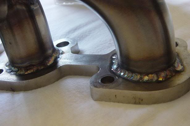
Some welds on the runners:
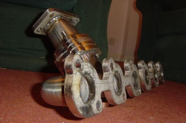
The T3 end of the mani:

The T25 sized flange showing a tiny bit of the baffling. For anyone who's interested, the HX27 doesn't bolt straight onto a T25 pattern flange as the Garret hole's a little bit too big. That's why there's a load of weld around the hole, I needed to make up filler pieces so the holes matched.

Here's the whole thing from another angle:
And lastly, the welds I was most proud of....although that's not saying much
The manifold's finished!
Just gotta leave it to settle for a couple of weeks and then take it to get skimmed.
Here's the finished article:
Some welds on the runners:
The T3 end of the mani:
The T25 sized flange showing a tiny bit of the baffling. For anyone who's interested, the HX27 doesn't bolt straight onto a T25 pattern flange as the Garret hole's a little bit too big. That's why there's a load of weld around the hole, I needed to make up filler pieces so the holes matched.
Here's the whole thing from another angle:
And lastly, the welds I was most proud of....although that's not saying much
Last edited by Turbo-Brown on Sun Sep 02, 2007 10:24 pm, edited 1 time in total.
-
Andy335Touring
- Married to the E30 Zone
- Posts: 7144
- Joined: Sun Jan 09, 2005 11:00 pm
- Location: Long Eaton,Nottingham
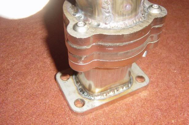
Excuse my thicko question but why use all those plates sandwhiched(sp?) together ?

-
Turbo-Brown
- Boost Junkie
- Posts: 4705
- Joined: Tue Feb 15, 2005 11:00 pm
- Location: Aldershot, Hants
Not a daft question at all dude!
Tow of the plates are welded to the mani and collector, and the middle two are going to form the bearings for the exhaust gas divertor butterfly.
I did have a thought about just welding two plates to the mani and machining them to accept the butterfly, but it occurs to me that the thing might get clagged up with soot etc so having a removable section was a good idea. Makes it easier to service and modify if needs be too.
-
Andy335Touring
- Married to the E30 Zone
- Posts: 7144
- Joined: Sun Jan 09, 2005 11:00 pm
- Location: Long Eaton,Nottingham
I see now, like you say it might be handy to be able to split it all down because it's going to be a harsh environment for a bearing/pivot !
What sort of thing will survive the heat yet not leak exhaust gas ?
What sort of thing will survive the heat yet not leak exhaust gas ?
-
Turbo-Brown
- Boost Junkie
- Posts: 4705
- Joined: Tue Feb 15, 2005 11:00 pm
- Location: Aldershot, Hants
Also a good question.
I'm going to go for a stainless steel spindle welded to a S/S buttefly. The far end of the spindle can be supported in a blind bearing (just a plain hole drilled on the split line of the plates but not all the way through) so that shouldn't leak.
The other end is gonna have a kind of labyrinth arrangement so there's a groove machined around that end of the spindle and a bit sticking out of the plates which locates in the groove. That gives the gas a couple of corners to turn before it can escape, plus a fairly tight clearance so it shouldn't be too bad......I hope anyway
-
gareth
- E30 Zone Team Member
- Posts: 11009
- Joined: Tue Jan 11, 2005 11:00 pm
- Location: hastings, east sussex
freezing and heating the manifold will help work out some of the residual stresses.
after machining then heat treatment on loadcells at work, we cycle them up to 100°C and then lob them in the freezer a few times.
looks good though, it has to be said!!!
you gonna get the brasso out and bling it?
after machining then heat treatment on loadcells at work, we cycle them up to 100°C and then lob them in the freezer a few times.
looks good though, it has to be said!!!
you gonna get the brasso out and bling it?
Sole founder of Fe2O3-12V it's a lifestyle

LSD rebuilding / modification services provided, PM for details
LSD rebuilding / modification services provided, PM for details
-
Turbo-Brown
- Boost Junkie
- Posts: 4705
- Joined: Tue Feb 15, 2005 11:00 pm
- Location: Aldershot, Hants
Crikey, was just gonna have it machined and be done with it, not sure the housemates would appreciated finding it in the freezer either
Had thought about going to town on doing a brushed finish, but it'll take no time at all for it all to start looking like it's been hot so there's probably not much point.
Had thought about going to town on doing a brushed finish, but it'll take no time at all for it all to start looking like it's been hot so there's probably not much point.
-
gareth
- E30 Zone Team Member
- Posts: 11009
- Joined: Tue Jan 11, 2005 11:00 pm
- Location: hastings, east sussex
in all fairness, a loadcell operates on stress and strain within the material so we do go a bit OTT sometimes!
Sole founder of Fe2O3-12V it's a lifestyle
LSD rebuilding / modification services provided, PM for details
LSD rebuilding / modification services provided, PM for details
-
Turbo-Brown
- Boost Junkie
- Posts: 4705
- Joined: Tue Feb 15, 2005 11:00 pm
- Location: Aldershot, Hants
Latest news:
Enquiries are out for materials to complete the inlet air system.
I've been doing lots of head scratching on the subject of control, looks like a MS daughter card (whatever that is) might be an answer
Enquiries are out for materials to complete the inlet air system.
I've been doing lots of head scratching on the subject of control, looks like a MS daughter card (whatever that is) might be an answer
-
Andy335Touring
- Married to the E30 Zone
- Posts: 7144
- Joined: Sun Jan 09, 2005 11:00 pm
- Location: Long Eaton,Nottingham
What sort of inlet are you planning ? ITB's ?
-
Turbo-Brown
- Boost Junkie
- Posts: 4705
- Joined: Tue Feb 15, 2005 11:00 pm
- Location: Aldershot, Hants
I am indeed, really big ones this time too
The basic setup will be a plenum for the boosted air to feed into over the rocker cover, a charge cooler which clips to the plenum, and a secondary plenum to distribute charge air into the new throttles.
I'm going for a set of 48mm throttles this time, again to my own design:

Wouldn't ordinarily use such large throttles for fear of losing all low end pull, but I don't think that's gonna be a problem if the system works so I can just concentrate on making the flow paths as generous as possible again.
The basic setup will be a plenum for the boosted air to feed into over the rocker cover, a charge cooler which clips to the plenum, and a secondary plenum to distribute charge air into the new throttles.
I'm going for a set of 48mm throttles this time, again to my own design:
Wouldn't ordinarily use such large throttles for fear of losing all low end pull, but I don't think that's gonna be a problem if the system works so I can just concentrate on making the flow paths as generous as possible again.
-
Andy335Touring
- Married to the E30 Zone
- Posts: 7144
- Joined: Sun Jan 09, 2005 11:00 pm
- Location: Long Eaton,Nottingham
They look ace !
I wish i could make up stuff like that.
I wish i could make up stuff like that.