http://www.e30.de/ka/showad.php?adid=109578


Moderator: martauto


i don't believe the MM manifold has anything to do with reversion regardless of what they say, like you said it is the pressure waves and a differing resonant frequency because of the extra chambersH35-24 wrote:What Kedge has found that Metric Mechanics do with the M42 intake is always present in all engines. It's wavetuning, and all manifolds intake and exhaust are in someway tuned to give the engine the torquecurve it has.
Basically there are 4 important things to know:
1. A Wave in air travel at the speed of sound, air waves are pressure peaks/drops.
2. When a change in geometry occurs, such as where a runner stops and a plenum starts, an air wave will stop and produce a reflection wave that returns down the runner.
3. A plenum can act as a resonater, that can pump air, it's known as a helmholz resonater.
4. The trick Metric mechanics use is, I can't remember it exactly but it's like when you open the window in a car and sometimes you get this intense pulse generation.
You'll also see it on an E36 M5x airfilterbox, but here the effect is probably to alter some unwanted intake noise.
So if you look at an M20 intake manifold, there are 6 equal length runners that all end in a plenum behind the throttle housing. The length of the runners give the max torque and the plenum acting as a helmholz resonater keeps the torque high in the bottom revs. This is also why the M20B20 and M20b25 have different manifolds, the runners are the same diameter inside, but the plenum is different.
When individual throttlebodies are used on engines like the M20 the increase in power does not come from having 6 TB's instead of one, it comes because the runners get shorter, a shorter runner will move the max torque higher up in the rpm-range and as we all know torque x rpm = bhp.
This usually also means the bottom end torque is decreased as the plenum has now been removed or has a size that makes it seem like its removed to the engine.
The only thing the individual throttle bodies give is a quicker throttle response.
Finally runner diameters are usually a compromise between performance and optiminum fuel/air mixing for best fuel economy.
That's at least what I read when studying my master degree, anyone read something different?

I was making these BBTB's for a while before I was moved off the machines. It's an expensive option to sacrifice an M30 TB when the butterfly is 2mm ally plate and the M20 shaft can be used with a bit of work from a needle file. Most of the work was the dismantling and reassembly.steve_k wrote:@h35-24 got a link to any info regarding the m20 TB with m30 internals?
I'm sure it could be a big help in this thread.
In my search for the Total BMW issue mentioning these BBTB's I came across another M20 TB mod. There is a complete 12 step how to do it guide for fitting a M20B25 TB on a M20B20 engine. Reasonably straight forward 1-2 hour job. And by doing a chip tuning in the end, the engine should gain a much a 10+% bhp.e301988325i wrote:I was making these BBTB's for a while before I was moved off the machines. It's an expensive option to sacrifice an M30 TB when the butterfly is 2mm ally plate and the M20 shaft can be used with a bit of work from a needle file. Most of the work was the dismantling and reassembly.steve_k wrote:@h35-24 got a link to any info regarding the m20 TB with m30 internals?
I'm sure it could be a big help in this thread.
The M20 body can be taken from 60mm dia to 64mm dia, something like a 15% increase in CSA.
I still have the two fixtures, one for holding the TB for boring and one for machining the new TB plate, which I would gladly sell as they're sat here doing nothing.
There is a noticeable improvement in throttle response, I believe this is due to removing a bit of restriction between the engine and AFM, I'm confident in saying the BBTB lets the engine rev more freely.
check brianmoores signature, it says something like when fitting a b25 TB to a b20, leave the b25 engine attached to the b25 TB.H35-24 wrote:In my search for the Total BMW issue mentioning these BBTB's I came across another M20 TB mod. There is a complete 12 step how to do it guide for fitting a M20B25 TB on a M20B20 engine. Reasonably straight forward 1-2 hour job. And by doing a chip tuning in the end, the engine should gain a much a 10+% bhp.e301988325i wrote:I was making these BBTB's for a while before I was moved off the machines. It's an expensive option to sacrifice an M30 TB when the butterfly is 2mm ally plate and the M20 shaft can be used with a bit of work from a needle file. Most of the work was the dismantling and reassembly.steve_k wrote:@h35-24 got a link to any info regarding the m20 TB with m30 internals?
I'm sure it could be a big help in this thread.
The M20 body can be taken from 60mm dia to 64mm dia, something like a 15% increase in CSA.
I still have the two fixtures, one for holding the TB for boring and one for machining the new TB plate, which I would gladly sell as they're sat here doing nothing.
There is a noticeable improvement in throttle response, I believe this is due to removing a bit of restriction between the engine and AFM, I'm confident in saying the BBTB lets the engine rev more freely.
So the TB's are where the horses are tied down it seems.


i just checked the bentley manual and it says the stock angles are 15-45-75HairyScreech wrote:Ok, i know i have been promising this for a while but meh, times have been tricky.
I got a chance to test the multi angle inserts i whipped up around christmas time and go over the data.
There are a couple of obvious issues with the data which i will address first.
1. The flow is measured at the wrong valve lift - yep this ones 100% my fault the spread sheet i use takes its lift values from the valve diameter and it was set to 36mm exhaust.
This means the flow was measured in steps 5% of an exhuast valve (1.8mm) rather than steps of 5% inlet diameter (2.1mm)
2. The flow seems to be a bit low - Not sure if this is an effect of the port or the surface finish of the seats as this was done on a different head to the other tests. I had a feeling the results would be effected by using an insert rather than a normal seat which is why i made a stock seat replica.
All these two issues mean is that the data cannot be taken as absolute, the tests only show the trend rather than the actual flow a multi angle seat will produce.
As long as we look at the data as showing a % improvement rather than a peak figure then its all ok.
Obviously i will try to sort these two issues out and get true figures but for now this tells us all we need to know. (and i had already done each test twice before i spotted the error so i though **** it ill deal with it later.)
On to the data.
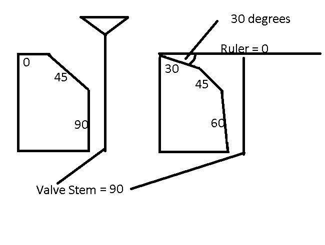
The valve seats have been referred to by there angle profile thus a stock seat is a 0/45/90, having a top face perpendicular to the valve stem, a sealing face at 45 degrees to the valve stem and a throat that is parallel to the valve stem.
The angle is measured as though a ruler had been put across the top of the seat and the flat of the ruler was regarded as 0.
Thus a 30 degree top cut would proceed away from the rulers edge at 30 degrees down into the port.
Its easier to draw so have some dick and quirty diagrams.
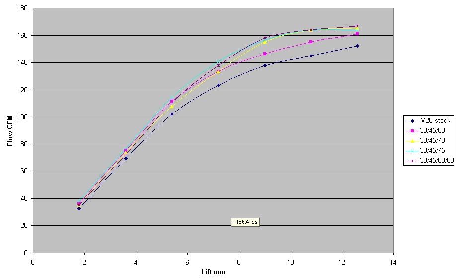
First things first the raw data.
This little chart has the seat profile down the left hand side, The lift value along the top and the Flow in CFM in the rest.
And this chart shows the contents of that table plotted.
Its pretty clear to see here that the best combination on the standard shape m20 port is the 30/45/75. Infact it matches the port and chamber so well it actually works better than a 4 angle.
the average improvement shown by the 30/45/75 over the range is about 13% which all things considered is a massive gain for a very simple alteration.
The plan from here is to test a port on this new head (late 89 rather than mid 85) and see if the lack of flow from the stock seat is due to the insert or the port or a combination of both.
Personally i think its a combination of both and would go a long way to explaining why some e30s are faster than others.
A proper steel 30/45/75 will also be prepared that will tell us the true gain from the multi angle, the inserts are cheap and quick for identifying the best profile but there's nothing like testing the real thing.
The other thing i will do is go to town on one of the ports and retest the inserts, it should help to see if the seats will need to be different once the ports have been worked or if they are more related to the throat and port/chamber angle.
Alot of heads have been refreshed at some point and therefore the head guy may have put something of his own concoction based on what tools he had.HairyScreech wrote:Interesting, i will have to check the heads i have here, as far as i can tell they are all 90/45.
Funny you should spot that as well, me and byron were talking and it seems not all heads were created equal, there seems to be no rhyme or reason for it but it seems some are a little bit closer to spec than others.
Pretty big thing if you have to run in a class with un ported heads, some have better seats than others and some have a lot less core shift/misalignment in the ports.
I guess it is dependent on the casting batch and who did the seats at the factory rather than year.


HairyScreech wrote:
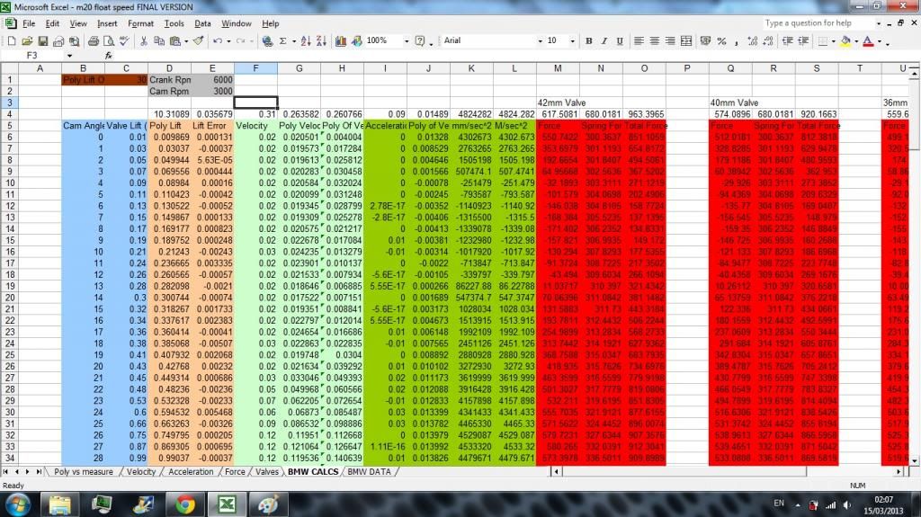
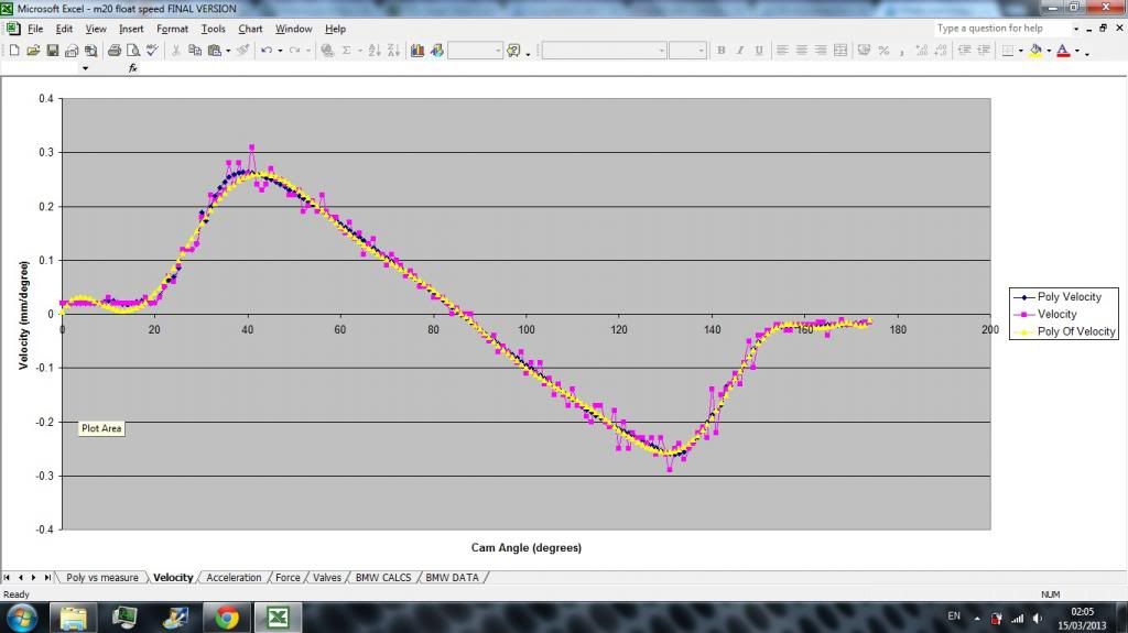
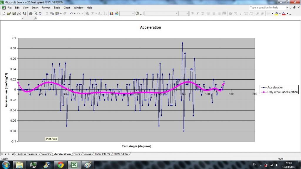
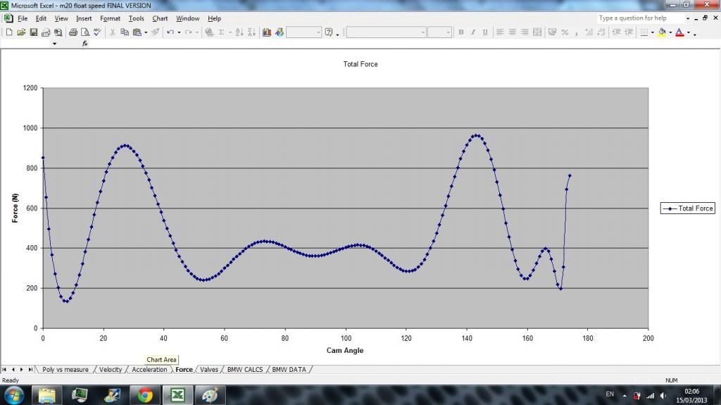
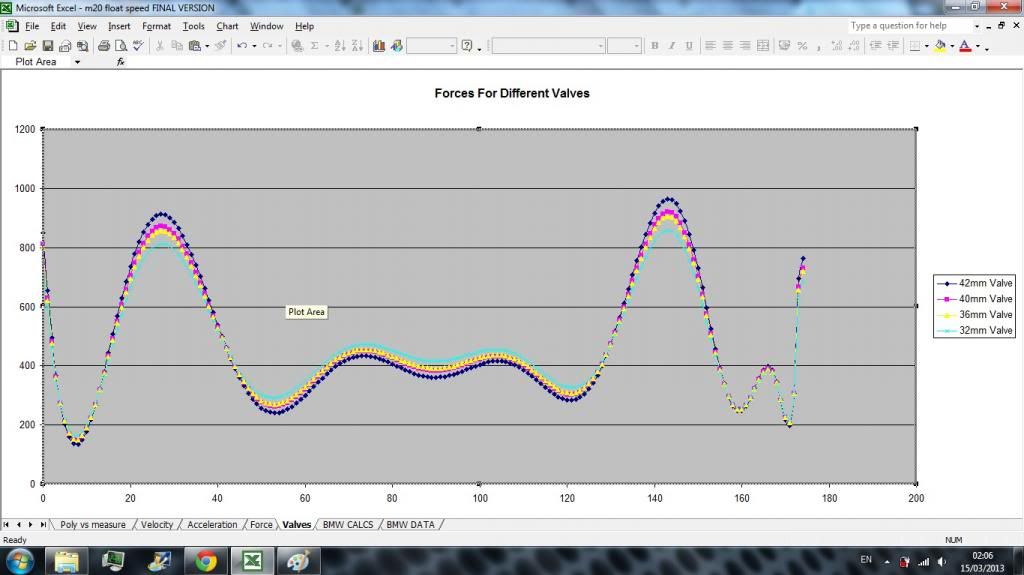
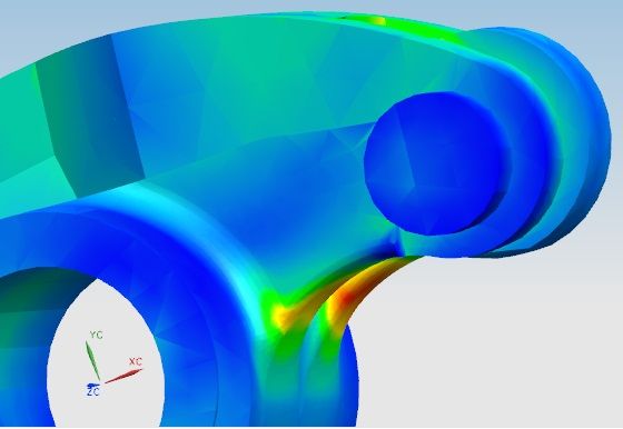
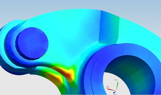
I have also developed a force model for the valves which has allowed me to get accurate rocker loads for any given rpm and point in the valve curve so have been able to run some pretty accurate FEA simulations of the rockers.
I'm currently working on a mathematical model that allows cam profiles to be converted to valve profiles for the complex m20 curved pad(like a roller) and rocker set up which defies normal simple mathematical cam contact models.
Its helliciously complicated so i probably wont post it into this thread but the guy i'm working with on it has said its not in any book and he has never seen it done mathematically before. (in a 50 year top level engineering career and a theoretical physics PHD).
There are for sure better ways but all require CAD and training.

so what made you conclude that there is a fatigue issue? (other than the obvious it is cast aluminium lol)HairyScreech wrote:Between me an malcolm we are not sure what the alloy is so a true S-N curve for the material is unknown.
Spring force to inertia force is about 1:1.23@7k. However i know of an inaccuracy in the valve motion model that will make this slightly inaccurate.
Yes there is the obvious of being alu.reggid wrote:so what made you conclude that there is a fatigue issue? (other than the obvious it is cast aluminium lol)HairyScreech wrote:Between me an malcolm we are not sure what the alloy is so a true S-N curve for the material is unknown.
Spring force to inertia force is about 1:1.23@7k. However i know of an inaccuracy in the valve motion model that will make this slightly inaccurate.
what sort of load magnitude are we talking?
According to MM the rockers break at quasi static load of 300-425lb depending on the brand. (maybe work out the material ”˜strength’ back calculating)?
If spring force is say 150lb (realistic) on a moderate high performance valve spring and cam at peak lift.
peak inertia effects do not coincide with maximum lift so the 1:1.2 ratio is this at a certain crank angle position?
To work out the failure mechanism you need some failed rockers and look at the fracture face to see if there is evidence of fatigue or simply that maladjusted valves and insufficient spring stiffness causes dynamic effects to escalate and cause fracture due to overload.
if we assume that peak spring force and peak inertia force coincide then some of the cheaper rockers should come close to breaking after 1 cycle but they actually do last pretty well considering.......the rockers I had that broke on a junk head I found broke by overload fracture due to belt failure. All the valves that bend failed a rocker. If the rockers do develop a crack I would suspect the crack size to cause fast fracture is quite small due to the poor fracture toughness and ductility of cast alloy and Al in general.HairyScreech wrote:Yes there is the obvious of being alu.reggid wrote:so what made you conclude that there is a fatigue issue? (other than the obvious it is cast aluminium lol)HairyScreech wrote:Between me an malcolm we are not sure what the alloy is so a true S-N curve for the material is unknown.
Spring force to inertia force is about 1:1.23@7k. However i know of an inaccuracy in the valve motion model that will make this slightly inaccurate.
what sort of load magnitude are we talking?
According to MM the rockers break at quasi static load of 300-425lb depending on the brand. (maybe work out the material ”˜strength’ back calculating)?
If spring force is say 150lb (realistic) on a moderate high performance valve spring and cam at peak lift.
peak inertia effects do not coincide with maximum lift so the 1:1.2 ratio is this at a certain crank angle position?
To work out the failure mechanism you need some failed rockers and look at the fracture face to see if there is evidence of fatigue or simply that maladjusted valves and insufficient spring stiffness causes dynamic effects to escalate and cause fracture due to overload.
We pretty much looked at the S-N curve of several cast alus that are used for other similar things and they were all looking a bit uncomfortable with the high rev stress.
The 1:1.23 ratio was just the max of the two spread sheet columns, thus max spring force vs max inertia. at the actual peak force they will indeed be different. I didn't think of that last night.
I will take a proper look at the numbers i used (spread sheet tots up and tells me the combined max without having to look at the individual numbers).
I did have some nice pics of broken rockers and a broken one kicking about, I will go looking for them.