Bullet Ride's ITB Project: I can go with the flow...
Posted: Tue Mar 12, 2013 7:59 pm
I have been posting about this build on a couple other E30 forums. I don't frequent here as often so I didn't really think about posting it here, but I figured you chaps might fancy a look at what I've got going on, and as always I value a good technical opinion 
I've been wanting to try my hand at a DIY ITB project for a little while now, and now that my 2.8L stroker has been up and running for a summer I figured that while it's away for the winter I'd try and hash out a design.
I've seen a handful of DIY M20 ITB set-ups on-line but I haven't come across very many well documented builds, and the one big thing that's usually missing is before and after dyno plots. I'm hoping to take my stroker to the dyno this spring and get some tuning done with the stock intake manifold, and then swap over to the ITBs and see what they can do.
My goals for this project are as follows:
- as always it's a budget build so try to keep the cost down by doing as much as I can on my own
- try to retain the stock brake booster if possible (most DIY set-ups I've seen are running a brake booster delete or remote booster)
- design the manifold so that it will be possible to try different size throttle bodies in the future if at all desired
- If I'm really feeling ambitious I may play with different length velocity stacks
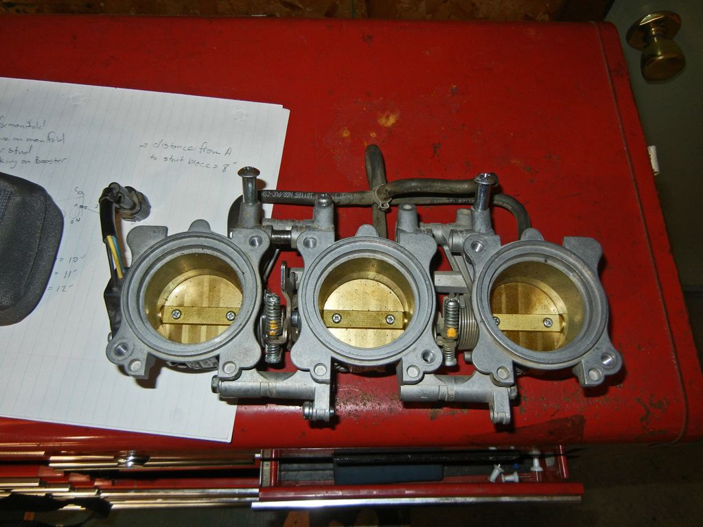
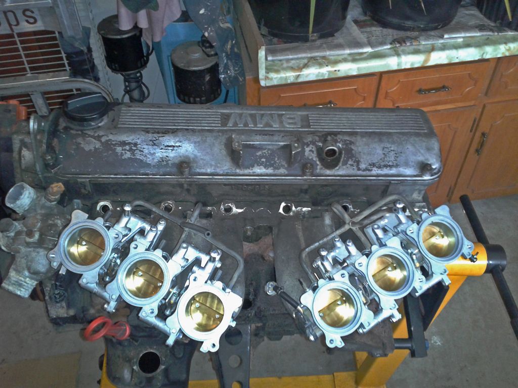
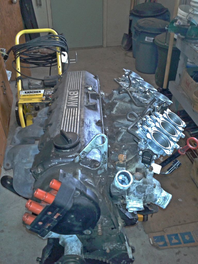
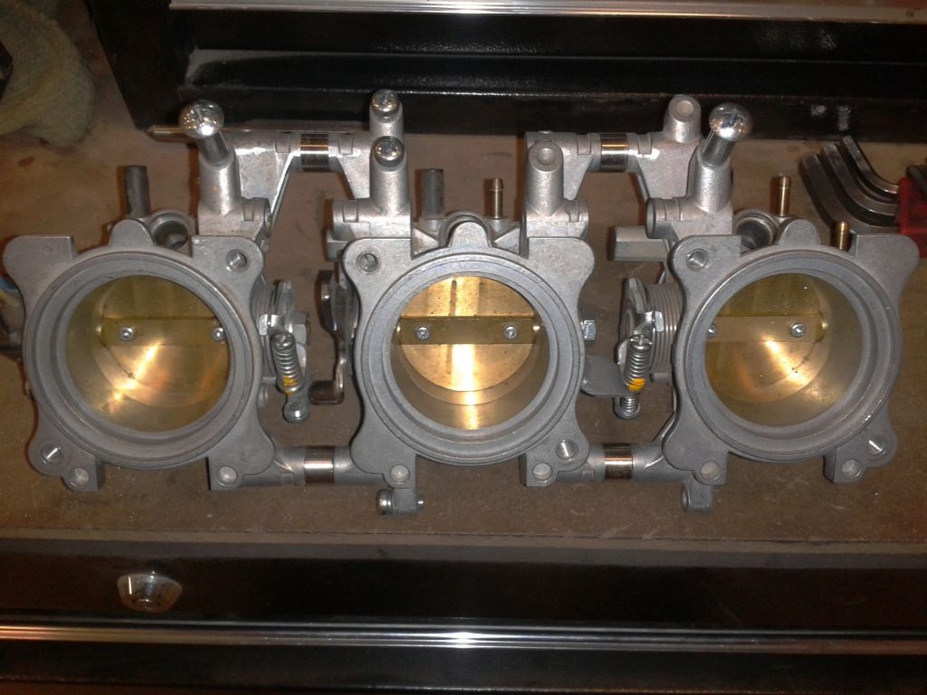
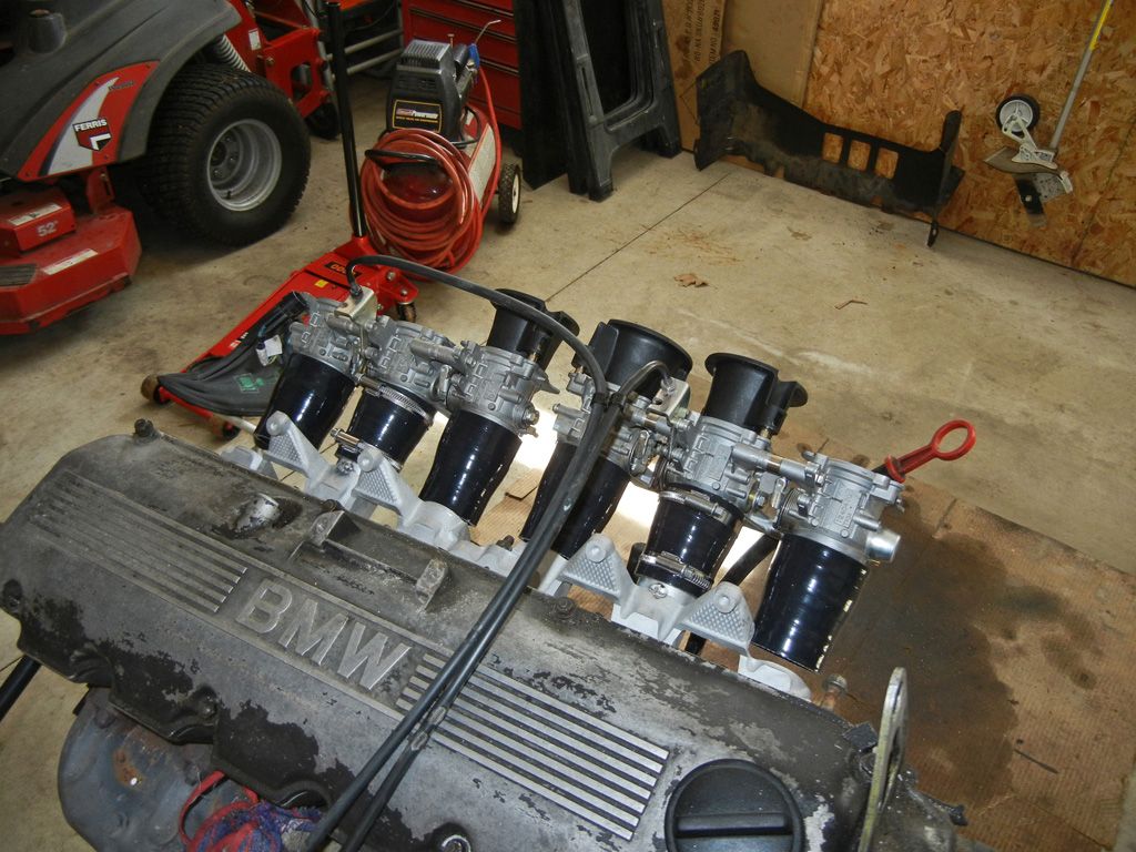
So the first thing I started with was finding some throttle bodies on the cheap. From what I've read, people seem to say that 38-40mm throttle bodies are what should be used (That's a whole thread on it's own so I'm not going to get into it here). From what I've seen GSXR 750, or BMW K75/K100 throttle bodies are good picks because they are in that size range and separable. However, at the time I was looking on ebay for throttle bodies there wasn't much available that fell into the price range that I wanted (aka dirt cheap lol). Then I came across some 2006-2009 Triumph Daytona/675 throttle bodies which seemed plentiful and some sets could be had for dirt cheap. The motorcycle aficionados amongst you will know that those bikes are triples, so two sets would give me 6 throttle bodies. The throttle body diameter is 44mm which is on the larger side (according to what people say) but they were so cheap that I couldn't pass them up, and since the manifold design is going to be somewhat modular, I could always try some smaller throttle bodies later if these happen to be junk.
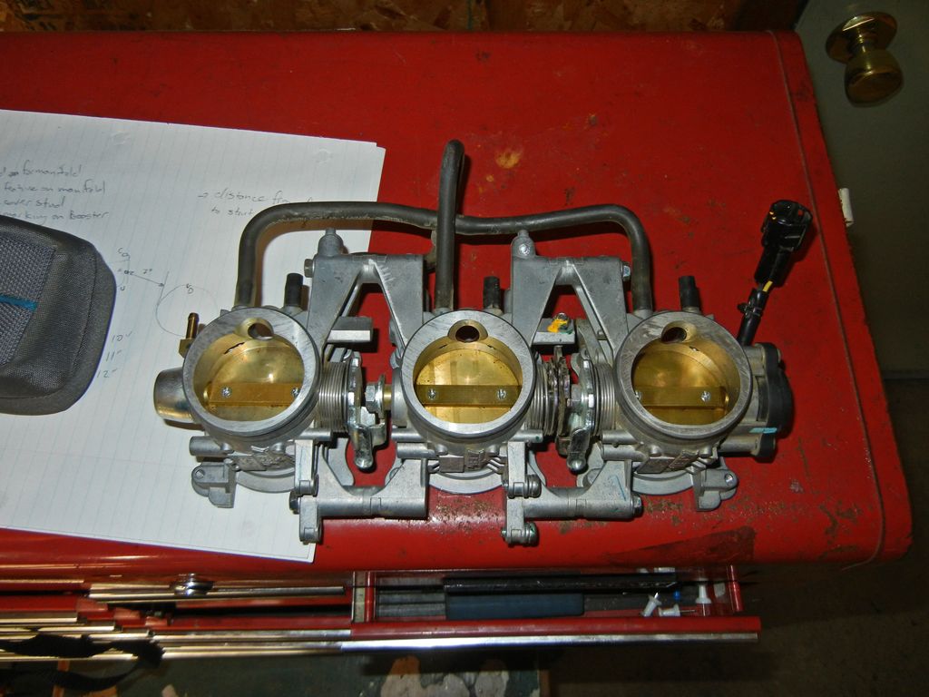
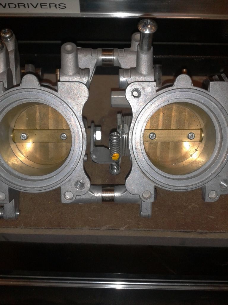
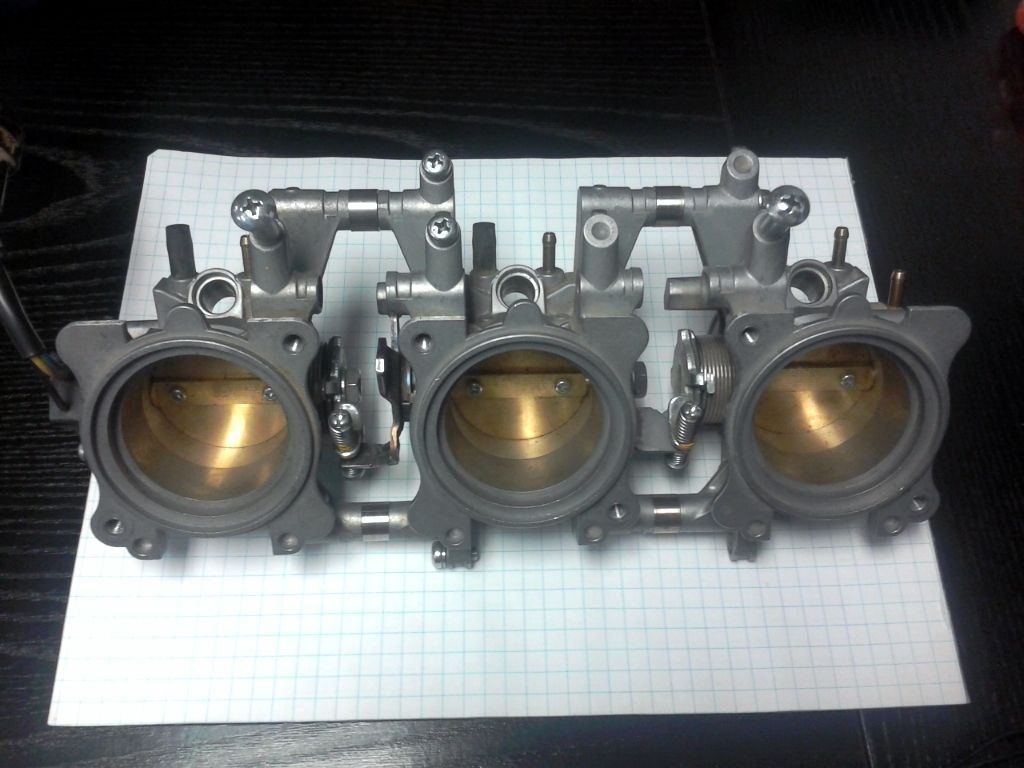
I was able to pick up two sets for $55 + another $55 or so for shipping so $110 (US dollars) for 6 throttle bodies. They are separable and look like this...
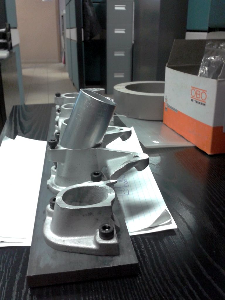
Then I set about hacking up the manifold from the motor I pulled when I swapped in my 2.8L stroker...
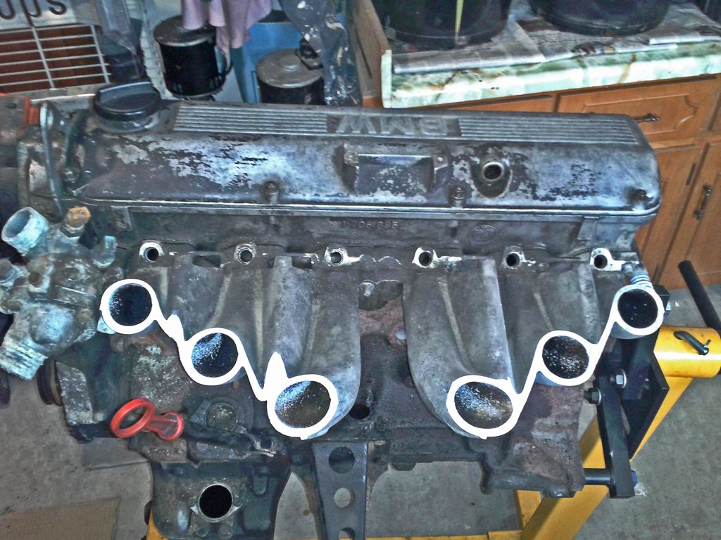
And that's when I had an epiphany.... I could mount the throttle bodies vertically and then cut my hood and run huge stacks out the top!!!
How gangster would that be......
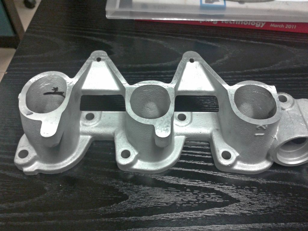
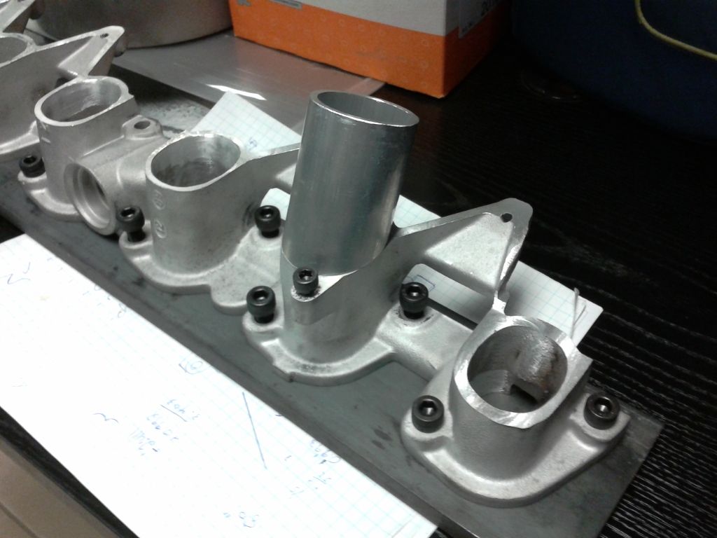
...not very gangster in my opinion so I continued hacking and after a little skim on the mill I ended up with this...
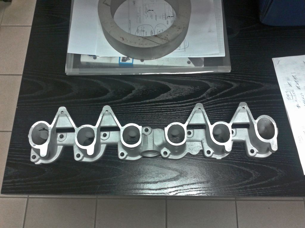
Now, as you can see the issue I had was that due to the angle on of the first and last runner the cross section of the cut is larger and that would pose a problem when going to weld on some new runner extensions. Using a straight edge I estimated roughly how far down I'd have to machine the runner for it to have roughly the same cross section. I'd like to retain the stock fuel rail mounting provisions if at all possible, so I'm only going to machine down the first and last runners and then make a decision as to whether or not the silicone couplers I plan on using will be able to compensate for the slight variation in angle on the two runners. The black line is roughly where I need to machine down to...
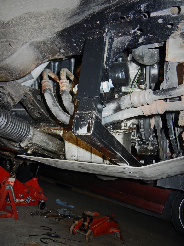
After that I wanted to take some measurements off of the car and develop a CAD model so I could come up with a rough design concept to check my clearances. Since it's hard to take measurements off of the car with all the wires and tubing in the engine bay in the way I decided to just use copper wire and touch off some key points relative to the manifold then cut the wire and attach it to the motor I had on the engine stand...
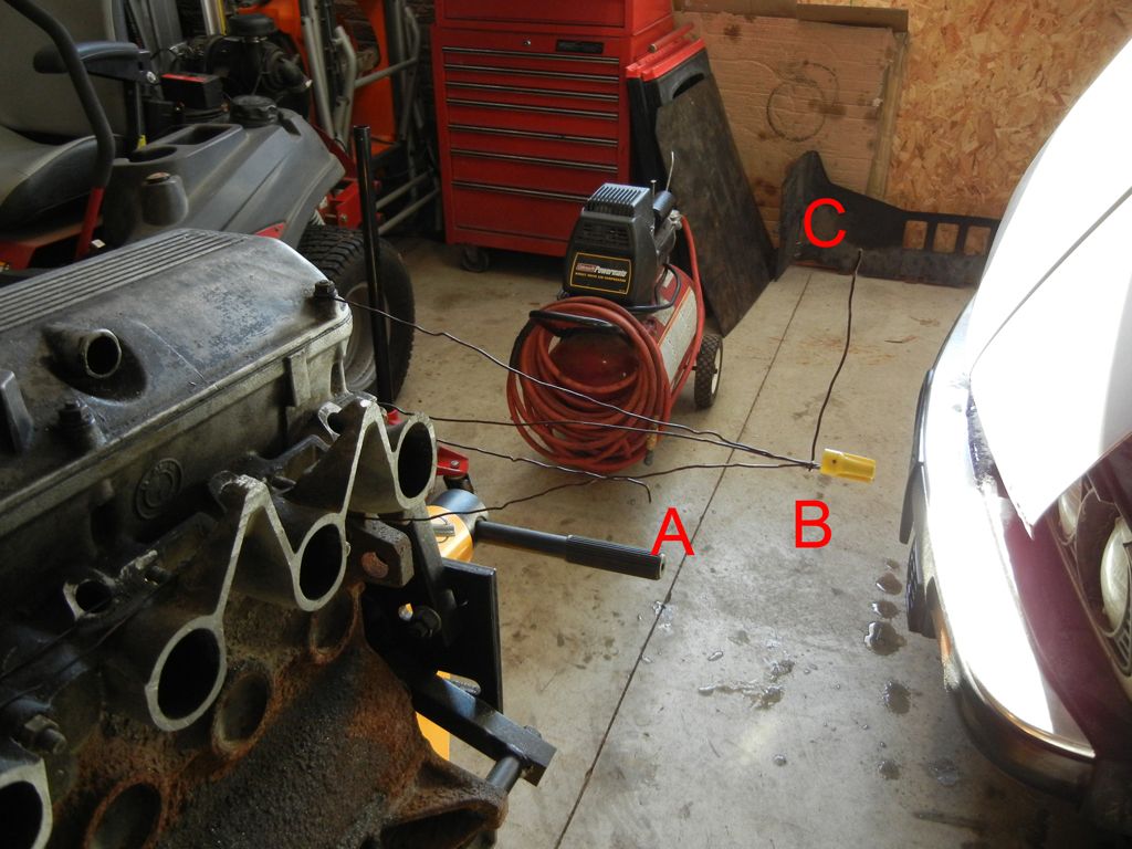
Point A (the horizontal piece with a small bend downwards) represents point on the brake booster that is closest to the intake manifold. Point B (the point where 3 wires come together) is a common point on the brake booster that will allow me to constrain the brake booster in my CAD model. Point B is also significant because I chose it by touching a wire off of a lower stud on the manifold and then laying it tangent to the brake booster. So as long as I can stay above the lower of the three wires I should be able to clear the brake booster. Finally Point C (the tip of the vertical wire) is a reference the lowest point on my strut brace that I could interfere with.
Then I took a side view holding the throttle bodies up at an angle that I thought might work and I imported it into autocad and scaled it so I could draw on it....

That way I was able to find roughly where the centre of the brake booster was as well as roughly what angle I will try out when I mock up the manifold. A 24 degree angle seems as though it will work.
The next step was to get my model going. I came across this drawing for the flange on some Swedish website for boosted cars...
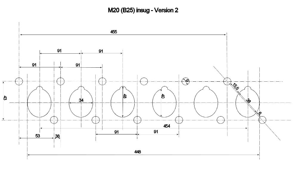
The rest of the measurements I just measured off of my manifold...

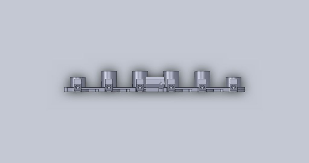
Adding some 1.75" x 0.125" wall tubing cut at a 24 degree angle. (The cross section of the 24 degree cut happens to match up fairly nicely with the cross section of the manifold). Also the tubes on the first and last ports are at a slightly lesser angle in order for the tips to match up.
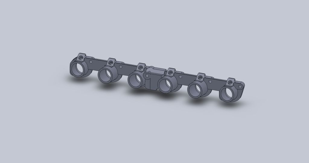
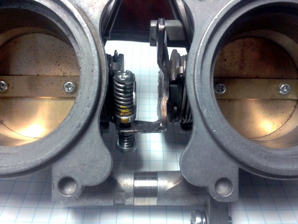
I roughly measured up the throttle bodies. In this picture they are spaced on 91mm centres just like the intake ports...


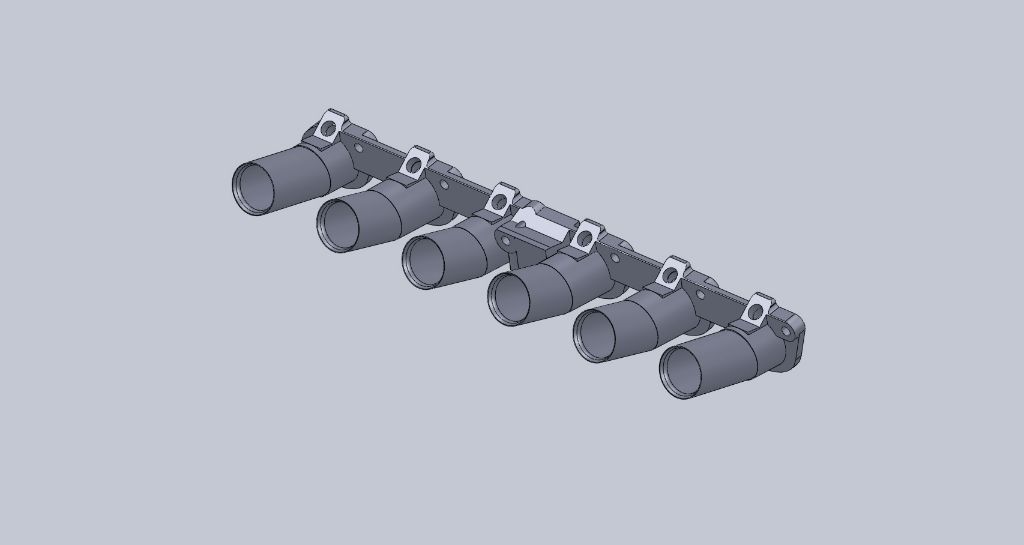
Putting it all together with some 2" to 1.75" silicone reducers looks something like this...
And with a rough estimate of the brake booster (I'm not actually sure of the placement of the booster depth wise but that's not really the limiting factor in this case)...

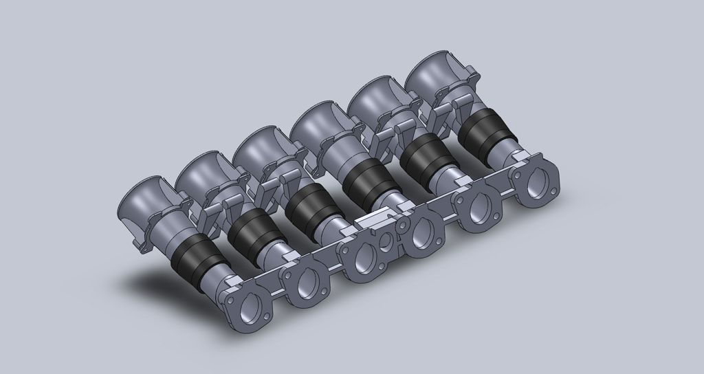
One observation that I had was that the outlet of the throttle body is actually roughly the same size as the cross section of the intake runner...
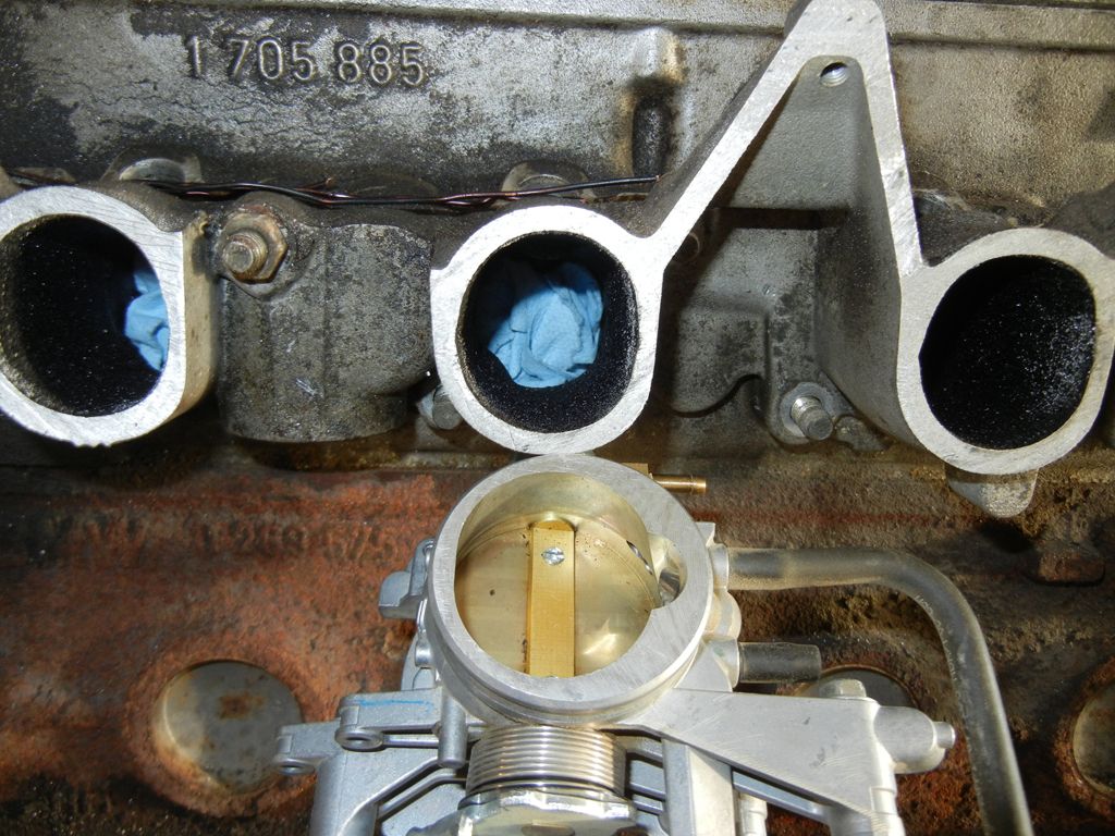
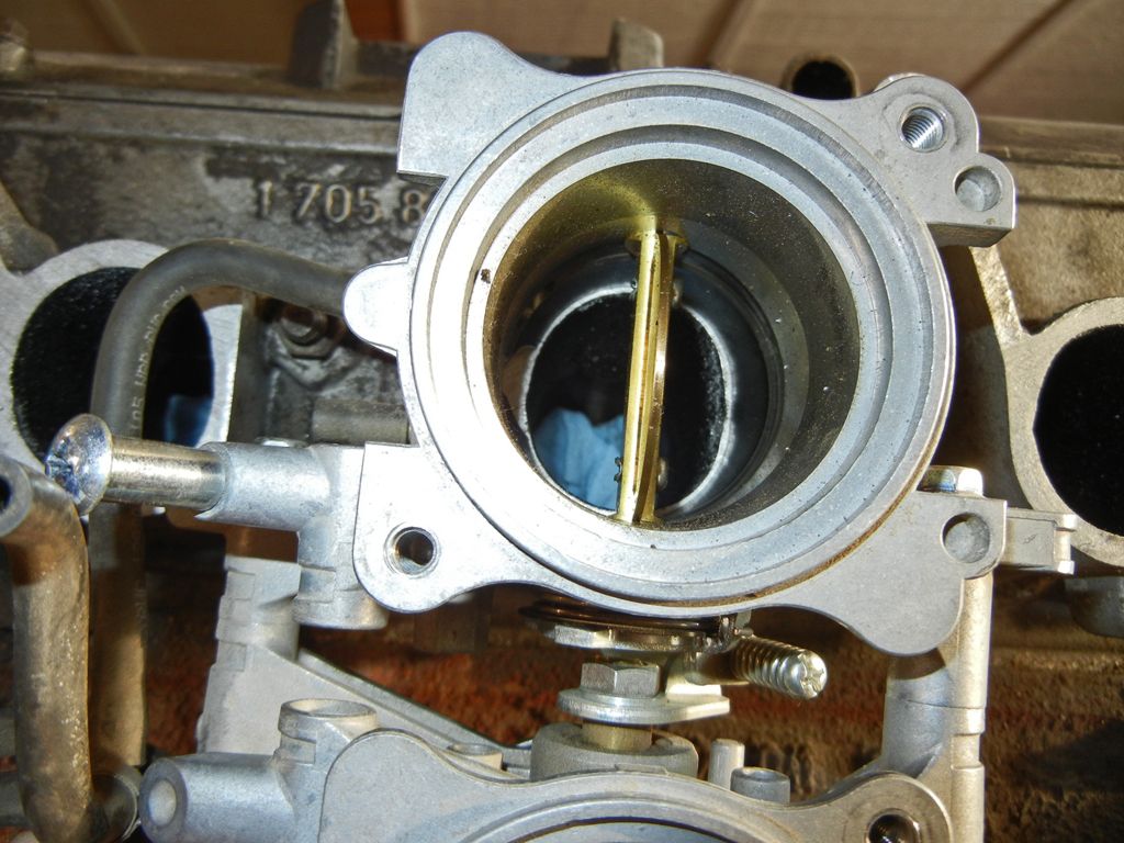
Unfortunately it's in the wrong orientation and off centre of the throttle body axis. It creates this situation in the transition...

I can blend the transitions so that going into the engine the air flow won't hit any steps, however any reversion will encounter a fairly big step at the exit of he throttle body. I'm not sure if this will have a positive or negative effect. It would be possible to bore out the throttle body so that it's round however I'm going to leave them be for now.
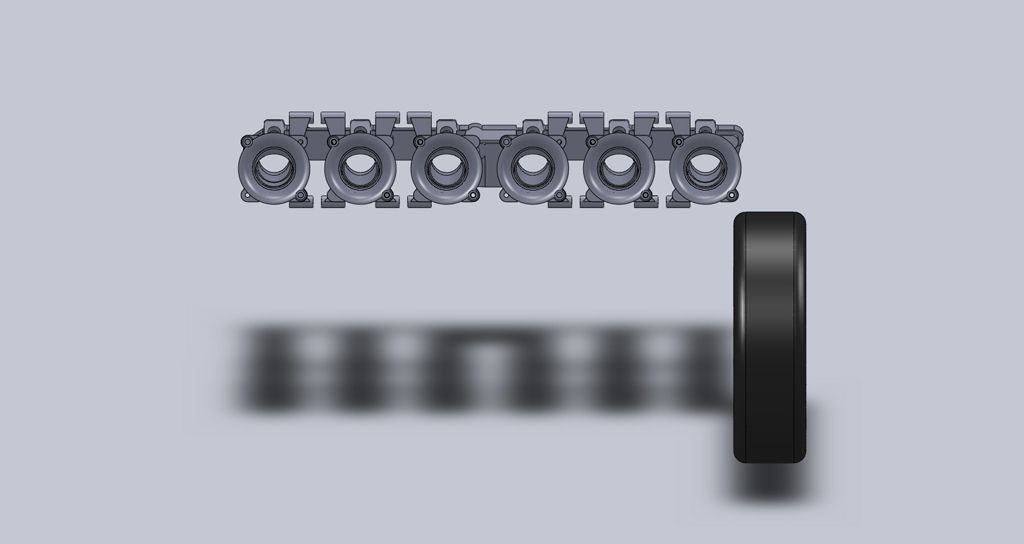
That pretty much brings me to where I am right now. I've ordered the silicone reducers as well as the aluminum tubing so it'll likely be a couple weeks before I'll have anything to update. However in the mean time I'm going to investigate potential methods of coupling both sets of throttle bodies and I'll work on making the spacers needed to space the throttle bodies as well as modifying the throttle syncing tabs to compensate for the spacing. One other consideration that I'm mashing around in my brain right now is making custom velocity stacks. I'm thinking of bringing them out at an angle towards the front of the car like this...
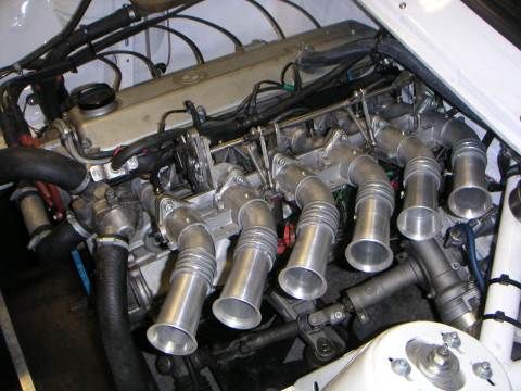
The reasoning is that it will allow me to have longer velocity stacks as well as afford me more space for air filters. However that will be on the back burner until I can get some test fitting done on the car.
I've been wanting to try my hand at a DIY ITB project for a little while now, and now that my 2.8L stroker has been up and running for a summer I figured that while it's away for the winter I'd try and hash out a design.
I've seen a handful of DIY M20 ITB set-ups on-line but I haven't come across very many well documented builds, and the one big thing that's usually missing is before and after dyno plots. I'm hoping to take my stroker to the dyno this spring and get some tuning done with the stock intake manifold, and then swap over to the ITBs and see what they can do.
My goals for this project are as follows:
- as always it's a budget build so try to keep the cost down by doing as much as I can on my own
- try to retain the stock brake booster if possible (most DIY set-ups I've seen are running a brake booster delete or remote booster)
- design the manifold so that it will be possible to try different size throttle bodies in the future if at all desired
- If I'm really feeling ambitious I may play with different length velocity stacks
So the first thing I started with was finding some throttle bodies on the cheap. From what I've read, people seem to say that 38-40mm throttle bodies are what should be used (That's a whole thread on it's own so I'm not going to get into it here). From what I've seen GSXR 750, or BMW K75/K100 throttle bodies are good picks because they are in that size range and separable. However, at the time I was looking on ebay for throttle bodies there wasn't much available that fell into the price range that I wanted (aka dirt cheap lol). Then I came across some 2006-2009 Triumph Daytona/675 throttle bodies which seemed plentiful and some sets could be had for dirt cheap. The motorcycle aficionados amongst you will know that those bikes are triples, so two sets would give me 6 throttle bodies. The throttle body diameter is 44mm which is on the larger side (according to what people say) but they were so cheap that I couldn't pass them up, and since the manifold design is going to be somewhat modular, I could always try some smaller throttle bodies later if these happen to be junk.
I was able to pick up two sets for $55 + another $55 or so for shipping so $110 (US dollars) for 6 throttle bodies. They are separable and look like this...
Then I set about hacking up the manifold from the motor I pulled when I swapped in my 2.8L stroker...
And that's when I had an epiphany.... I could mount the throttle bodies vertically and then cut my hood and run huge stacks out the top!!!
How gangster would that be......
...not very gangster in my opinion so I continued hacking and after a little skim on the mill I ended up with this...
Now, as you can see the issue I had was that due to the angle on of the first and last runner the cross section of the cut is larger and that would pose a problem when going to weld on some new runner extensions. Using a straight edge I estimated roughly how far down I'd have to machine the runner for it to have roughly the same cross section. I'd like to retain the stock fuel rail mounting provisions if at all possible, so I'm only going to machine down the first and last runners and then make a decision as to whether or not the silicone couplers I plan on using will be able to compensate for the slight variation in angle on the two runners. The black line is roughly where I need to machine down to...
After that I wanted to take some measurements off of the car and develop a CAD model so I could come up with a rough design concept to check my clearances. Since it's hard to take measurements off of the car with all the wires and tubing in the engine bay in the way I decided to just use copper wire and touch off some key points relative to the manifold then cut the wire and attach it to the motor I had on the engine stand...
Point A (the horizontal piece with a small bend downwards) represents point on the brake booster that is closest to the intake manifold. Point B (the point where 3 wires come together) is a common point on the brake booster that will allow me to constrain the brake booster in my CAD model. Point B is also significant because I chose it by touching a wire off of a lower stud on the manifold and then laying it tangent to the brake booster. So as long as I can stay above the lower of the three wires I should be able to clear the brake booster. Finally Point C (the tip of the vertical wire) is a reference the lowest point on my strut brace that I could interfere with.
Then I took a side view holding the throttle bodies up at an angle that I thought might work and I imported it into autocad and scaled it so I could draw on it....
That way I was able to find roughly where the centre of the brake booster was as well as roughly what angle I will try out when I mock up the manifold. A 24 degree angle seems as though it will work.
The next step was to get my model going. I came across this drawing for the flange on some Swedish website for boosted cars...
The rest of the measurements I just measured off of my manifold...
Adding some 1.75" x 0.125" wall tubing cut at a 24 degree angle. (The cross section of the 24 degree cut happens to match up fairly nicely with the cross section of the manifold). Also the tubes on the first and last ports are at a slightly lesser angle in order for the tips to match up.
I roughly measured up the throttle bodies. In this picture they are spaced on 91mm centres just like the intake ports...
Putting it all together with some 2" to 1.75" silicone reducers looks something like this...
And with a rough estimate of the brake booster (I'm not actually sure of the placement of the booster depth wise but that's not really the limiting factor in this case)...
One observation that I had was that the outlet of the throttle body is actually roughly the same size as the cross section of the intake runner...
Unfortunately it's in the wrong orientation and off centre of the throttle body axis. It creates this situation in the transition...
I can blend the transitions so that going into the engine the air flow won't hit any steps, however any reversion will encounter a fairly big step at the exit of he throttle body. I'm not sure if this will have a positive or negative effect. It would be possible to bore out the throttle body so that it's round however I'm going to leave them be for now.
That pretty much brings me to where I am right now. I've ordered the silicone reducers as well as the aluminum tubing so it'll likely be a couple weeks before I'll have anything to update. However in the mean time I'm going to investigate potential methods of coupling both sets of throttle bodies and I'll work on making the spacers needed to space the throttle bodies as well as modifying the throttle syncing tabs to compensate for the spacing. One other consideration that I'm mashing around in my brain right now is making custom velocity stacks. I'm thinking of bringing them out at an angle towards the front of the car like this...
The reasoning is that it will allow me to have longer velocity stacks as well as afford me more space for air filters. However that will be on the back burner until I can get some test fitting done on the car.


 [/img]