OBC Check panel Voltmeter install DIY guide
Posted: Tue Oct 06, 2015 12:17 am
I recently had a go at making my own check panel digital voltmeter for my E30 and posted some pictures up.
I then received a few PM's asking how it was done so as promised here is a write up for all of those who asked.
Please guys do this at your own risk, I purchased a spare from ebay and modified that one.
Also let me start by saying it is not a perfect conversion but it was the first try but still worked out well to the eye but I could and would be better if I tried it again as now I know what is involved.
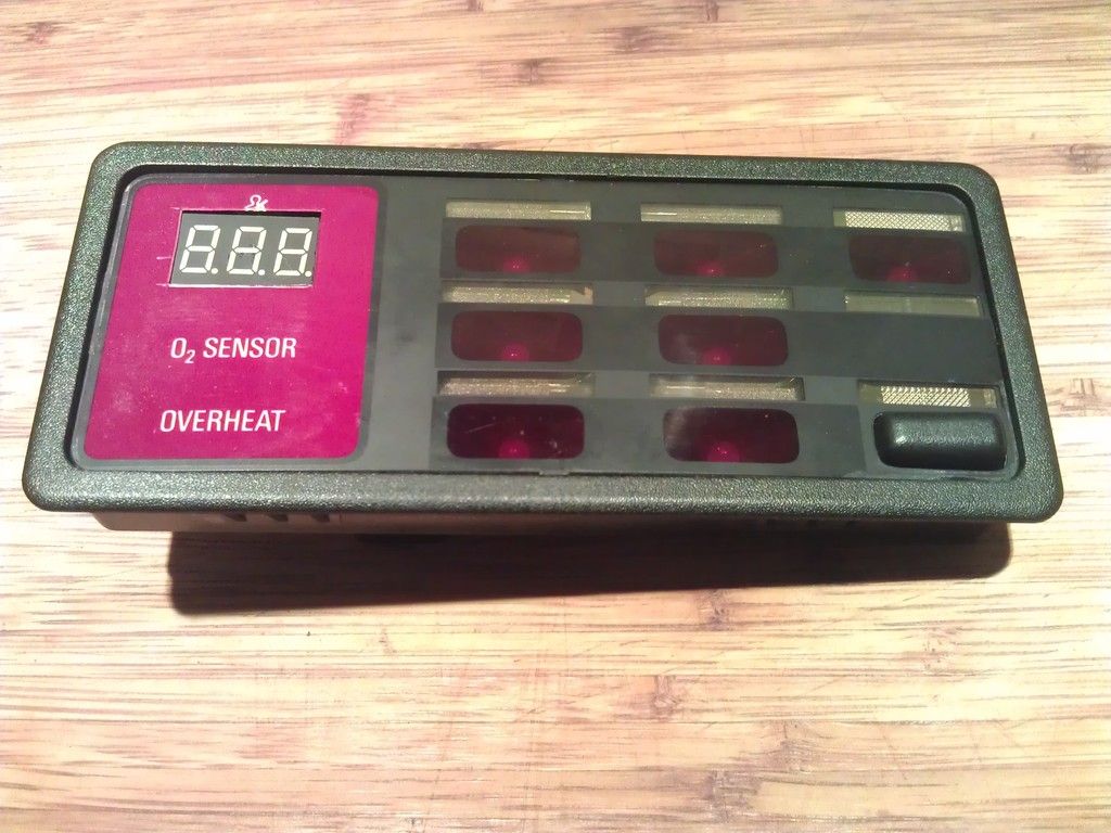
Here is what you should end up with, I have had to take my check panel apart again to take pictures for this guide so the steps are already finished.

Ok
I have seen 2 different types of check panel and there might be more but I used the type below, If you have something different I would presume the steps would be slightly different.
So I purchased a 2 wire red digital voltmeter 2.5/30V from ebay for something like £1 to £3 dimensions are 23x15x10mm
I then removed the 2 end tabs as they were getting in the way for me but for now leave them on and remove if required.

Next up was to start to dismantle the OBC panel.
For me at first look I thought that this was a sealed unit as the back is one mounlded unit, Upon close inspection I could see that the front actually would come apart so I began to try to figure this out and eventually I managed to open it without breaking anything as it is a bit tricky.
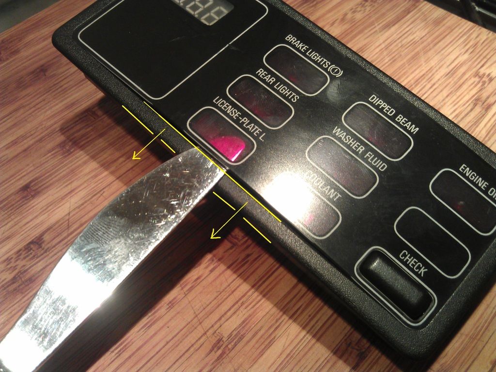
First you have to pull the sides away to get a small gap so you can do this by pulling it apart with both hands and then get a friend to slip in something flat (knife/Plastic wedge etc). Make sure it is in the bottom of the panel as shown.
Once the bottom is popped out then go to the top and pop the top out making sure not to break this small tab

Then once the sides are free you need to bend the top cover outwards so it curves and this would make it shorter in length and this will enable the end tabs to pop out free, Dont go too mad though the cover is fragile but it will flex.

Once out you can see the end tabs below.


Then you are left with the lower cover to remove, This is pretty simple and more or less the same as the first top cover but has some more flex and is easier to remove.
Note the small tabs when removed.
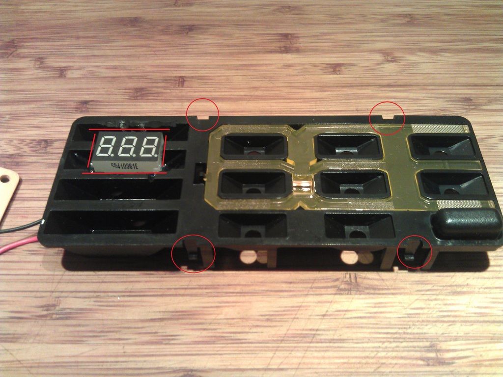
Now we are almost there, Again just a few small tabs note the 4 small rectangular holes and the plastic should pull out, Also the circuit board will come out with this, you can gently push from the rear, Also there was no need for me to remove the small bulb/bulbs from the rear but remove if required.

Note below 4 small tabs for removal.
Once this is removed the circuit board will be free and be moved aside.
Now the fun starts.
Position your voltmeter in the desired position on the left side, I wanted the position as per my pictures, Then mask off or scribe some guide lines and cut using a Dremel or something similar, If you do not own a Dremel it might be possible another way but just take your time and be safe.
Once your hole is cut make sure the voltmeter sits nice in the slot and does not stick out at all otherwise you will not get the unit back together, Now is the time to cut voltmeter tabs off if required (This is important) Also feed the voltmeter wires through one of the holes where the bulbs go or if your Check control has bulbs drill a new hole for the 2 wires.

Use suitable glue, I used Epoxy glue and make sure the voltmeter is sitting parallel otherwise it will look a mess.

Hopefully it should look like this once your glue has dried off, I suggest 24hrs.

Now for the soldering.
Ok have a look at the rear plastic cover where the wiring loom plugs into the unit and there should be some numbers printed on each corner 1,13,14,26 This corresponds to the pin location on the plug and unit.
Now the voltmeter has 2 wires Red + and black -
I connected as follows
Pin 9 Brown wire = Ground/Black wire On Voltmeter
Pin23 Violet/Green = Switched 12V red wire on Voltmeter
I wanted my voltmeter to only come on when I switched my ignition on as I do not want my voltmeter to drain my battery when not in use.
For anyone wanting to connect the voltmeter to constant live you can connect to pin 15 Red/Green or Red . But that would drain your battery.
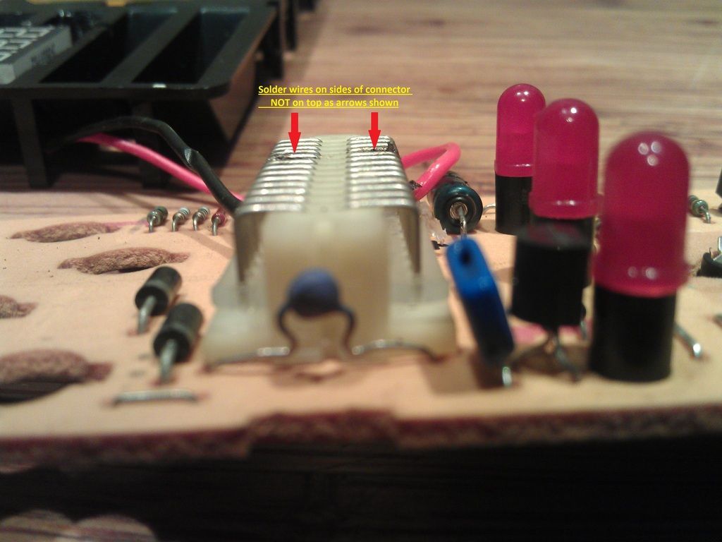
So now to solder it together, My 1st attempt went wrong as I soldered the wires to the top of the connector and then found out the wiring got in the way on re assembly, So the wires were soldered to the sides of the connector as shown, Also I tried to solder with no flux and made a bit of a mess, I eventually got flux paste and managed to make a good solder in the end. Also make sure no wire or connection when soldered touches any of the other pins this will short out your car etc.

Note not to solder here
Once your happy with soldering you can re assemble, Push the board and plastic cover back together but making sure the wiring does not get trapped between the plastic legs as again the unit will not go back together correctly,Picture below.
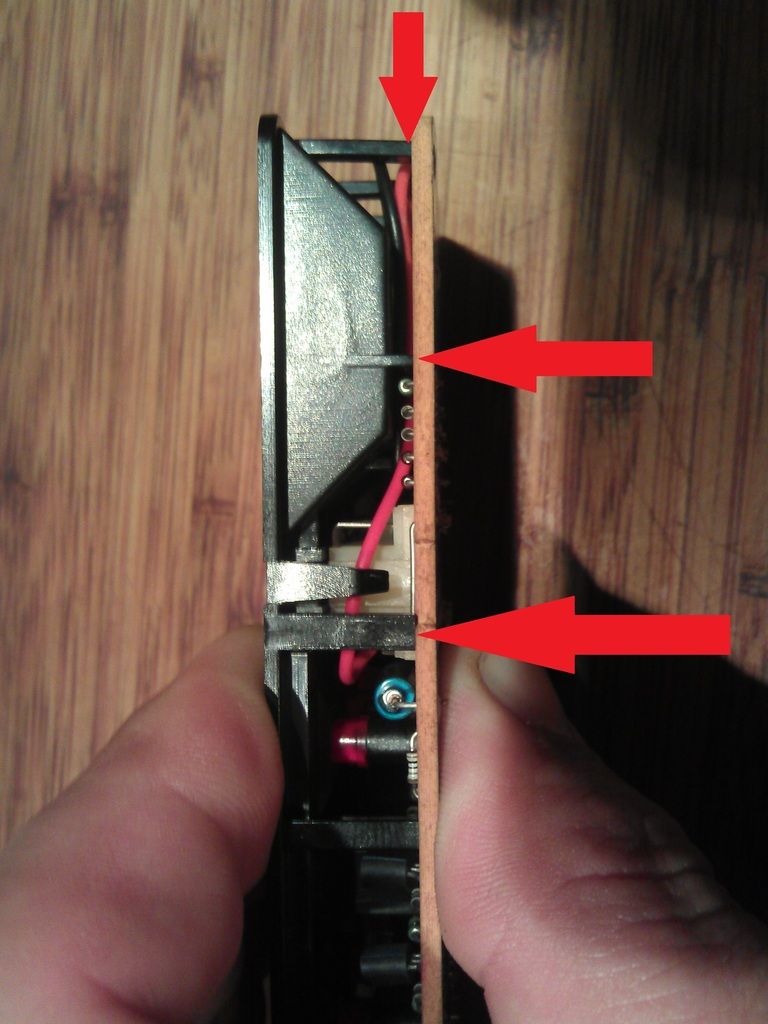
Once these are together ok you can re insert them back into the main plastic body making sure they do not separate and trap the voltmeter wires.
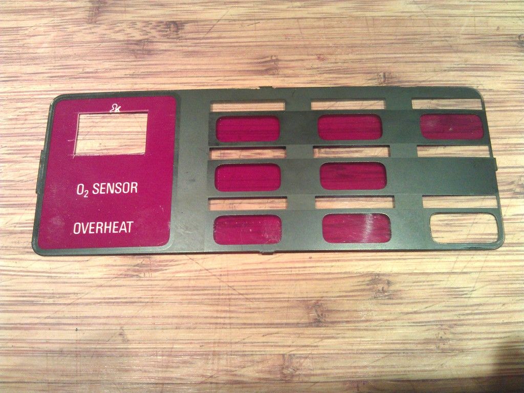
Now place the red cover over your voltmeter and carefully mark out where to cut your hole, the more time you spend on this the neater it is going to look, I used a stanley knife with a new blade and it cut fine.

I then received a few PM's asking how it was done so as promised here is a write up for all of those who asked.
Please guys do this at your own risk, I purchased a spare from ebay and modified that one.
Also let me start by saying it is not a perfect conversion but it was the first try but still worked out well to the eye but I could and would be better if I tried it again as now I know what is involved.
Here is what you should end up with, I have had to take my check panel apart again to take pictures for this guide so the steps are already finished.

Ok
I have seen 2 different types of check panel and there might be more but I used the type below, If you have something different I would presume the steps would be slightly different.
So I purchased a 2 wire red digital voltmeter 2.5/30V from ebay for something like £1 to £3 dimensions are 23x15x10mm
I then removed the 2 end tabs as they were getting in the way for me but for now leave them on and remove if required.

Next up was to start to dismantle the OBC panel.
For me at first look I thought that this was a sealed unit as the back is one mounlded unit, Upon close inspection I could see that the front actually would come apart so I began to try to figure this out and eventually I managed to open it without breaking anything as it is a bit tricky.
First you have to pull the sides away to get a small gap so you can do this by pulling it apart with both hands and then get a friend to slip in something flat (knife/Plastic wedge etc). Make sure it is in the bottom of the panel as shown.

Once the bottom is popped out then go to the top and pop the top out making sure not to break this small tab

Then once the sides are free you need to bend the top cover outwards so it curves and this would make it shorter in length and this will enable the end tabs to pop out free, Dont go too mad though the cover is fragile but it will flex.

Once out you can see the end tabs below.


Then you are left with the lower cover to remove, This is pretty simple and more or less the same as the first top cover but has some more flex and is easier to remove.

Note the small tabs when removed.

Now we are almost there, Again just a few small tabs note the 4 small rectangular holes and the plastic should pull out, Also the circuit board will come out with this, you can gently push from the rear, Also there was no need for me to remove the small bulb/bulbs from the rear but remove if required.

Note below 4 small tabs for removal.

Once this is removed the circuit board will be free and be moved aside.
Now the fun starts.
Position your voltmeter in the desired position on the left side, I wanted the position as per my pictures, Then mask off or scribe some guide lines and cut using a Dremel or something similar, If you do not own a Dremel it might be possible another way but just take your time and be safe.
Once your hole is cut make sure the voltmeter sits nice in the slot and does not stick out at all otherwise you will not get the unit back together, Now is the time to cut voltmeter tabs off if required (This is important) Also feed the voltmeter wires through one of the holes where the bulbs go or if your Check control has bulbs drill a new hole for the 2 wires.

Use suitable glue, I used Epoxy glue and make sure the voltmeter is sitting parallel otherwise it will look a mess.

Hopefully it should look like this once your glue has dried off, I suggest 24hrs.

Now for the soldering.
Ok have a look at the rear plastic cover where the wiring loom plugs into the unit and there should be some numbers printed on each corner 1,13,14,26 This corresponds to the pin location on the plug and unit.
Now the voltmeter has 2 wires Red + and black -
I connected as follows
Pin 9 Brown wire = Ground/Black wire On Voltmeter
Pin23 Violet/Green = Switched 12V red wire on Voltmeter
I wanted my voltmeter to only come on when I switched my ignition on as I do not want my voltmeter to drain my battery when not in use.
For anyone wanting to connect the voltmeter to constant live you can connect to pin 15 Red/Green or Red . But that would drain your battery.
So now to solder it together, My 1st attempt went wrong as I soldered the wires to the top of the connector and then found out the wiring got in the way on re assembly, So the wires were soldered to the sides of the connector as shown, Also I tried to solder with no flux and made a bit of a mess, I eventually got flux paste and managed to make a good solder in the end. Also make sure no wire or connection when soldered touches any of the other pins this will short out your car etc.

Note not to solder here

Once your happy with soldering you can re assemble, Push the board and plastic cover back together but making sure the wiring does not get trapped between the plastic legs as again the unit will not go back together correctly,Picture below.

Once these are together ok you can re insert them back into the main plastic body making sure they do not separate and trap the voltmeter wires.
Now place the red cover over your voltmeter and carefully mark out where to cut your hole, the more time you spend on this the neater it is going to look, I used a stanley knife with a new blade and it cut fine.


