Building a m20 bottom end..
Posted: Fri Sep 25, 2015 5:50 am
A little while ago I started a guid for people interested in building there own motors....
Aim is to show people it isn't that daunting and actually quite easy...
Enjoy
Building a m20 6 cylinder engine...
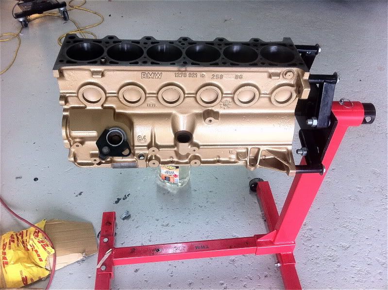
First thing to do is strip the engine down to its pants leaving just the engine block. Be sure to number the rods and pistons and place a little marker on them showing what direction the where removed from the block. It is absolutely critical that reassembly is the exact revers of how they were removed. You must mark the pistons the rods and the bearing caps, I put numbers and arrows with a paint marker so there can be no confusion.
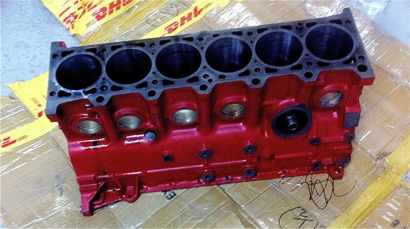
Send the block away to your machinist and have them clean, hone and reface it.
It should come back looking something like this.
Honing.
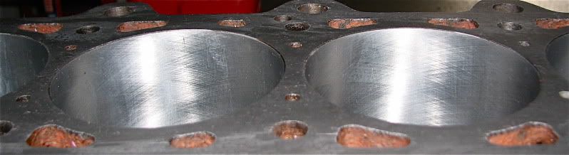
Refaced.
The next thing you want to do is thoroughly clean it, even though you had the machinist clean it I promise you it will be filthy dirty. You need to use
petrol, kerosene or turpentine. I used all three in that order and then finished with some prepsol/ wax and grease remover. You need to use a air compressor and flush out all the oil ways to ensure there is no swarf or blockages as this will kill your new engine in seconds.
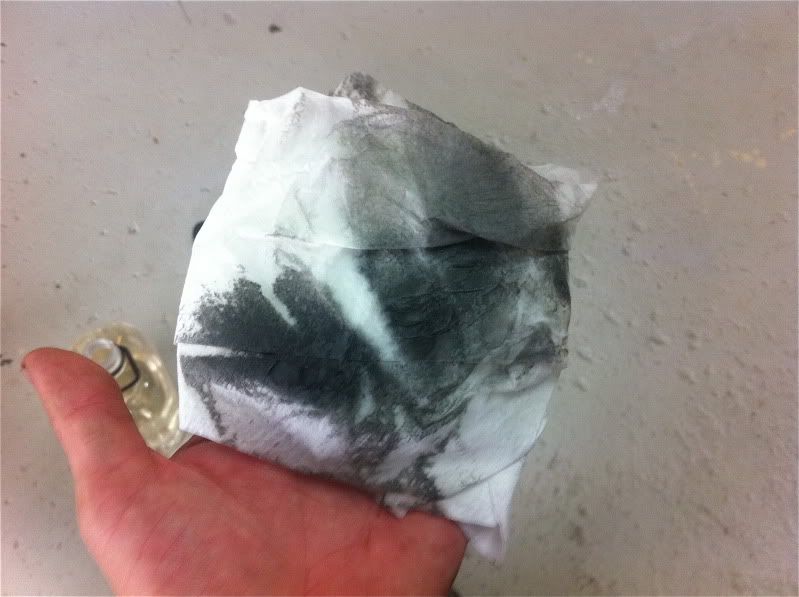
When you think its clean go over it again with tissue paper and when the tissue paper comes back clean with no grease or dirt you are ready to assemble.
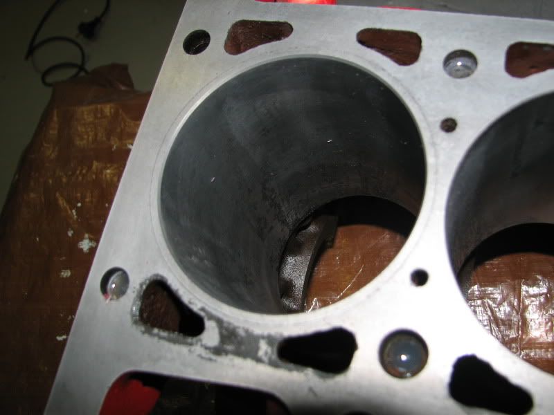
This is typically how it will be strait from the machine shop.
Time for a fresh coat of paint.
Now if you are using your old piston and rod combo you can skip tis step.
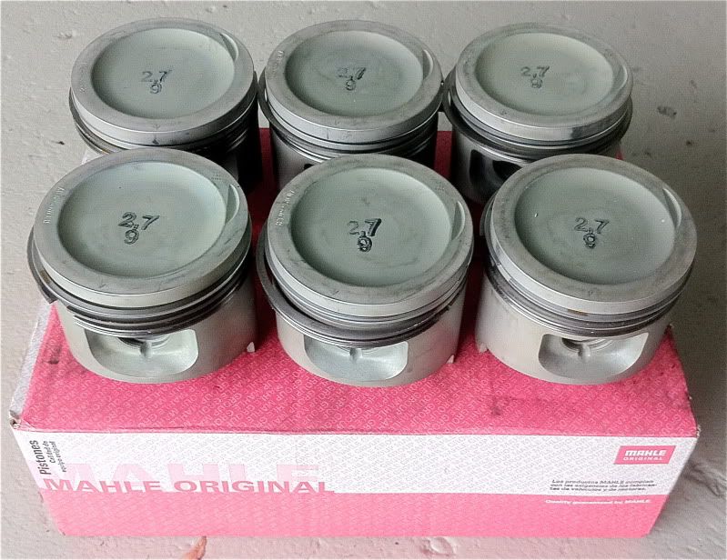
Six brand new mahle pistons.
First thing to do is remove the old pistons off the rods... Be sure to do it in order as it is very very important that the rods go back in the block the same order the where removed.
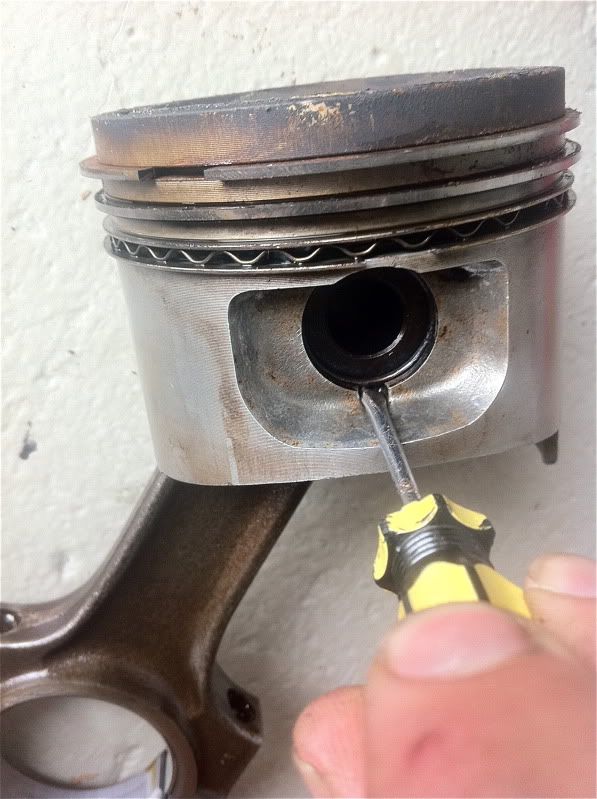
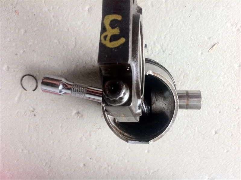
Removing the cirlcip.
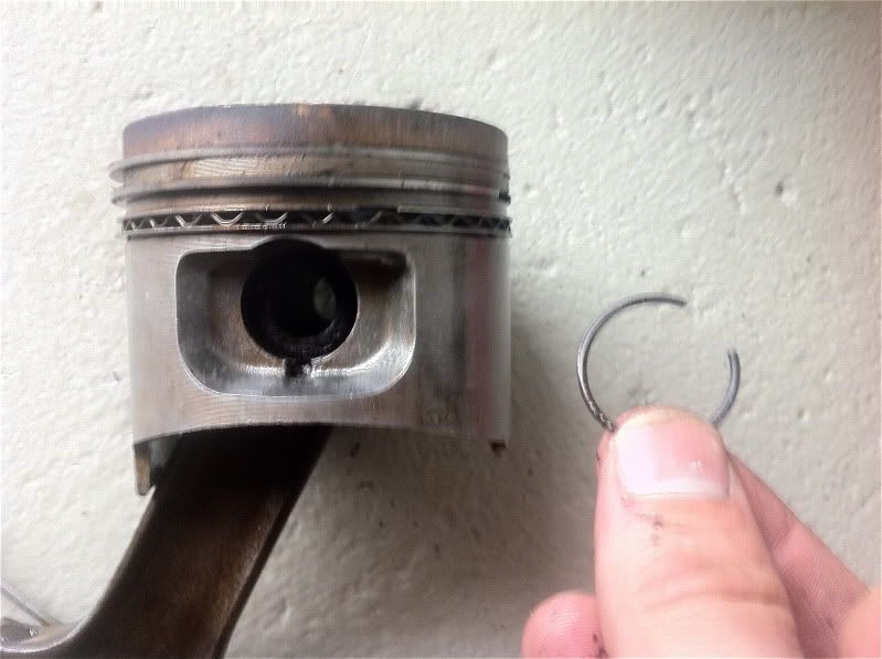
Nock the gudgeon pin through the piston using a suitable drift, be carefull not to damage anything... It makes it easier if you soak it in hot water first to let the metals expand a little.
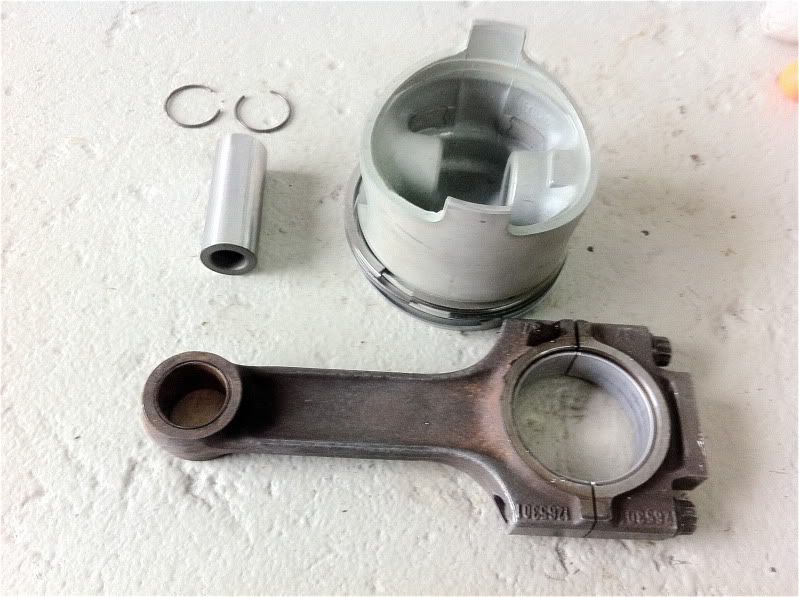
Ready to reassemble with new piston gudgeon pin and circlips.
The cirlcip goes in this little groove with the greatest of care and frustration, expect a few nicks off your fingers and circlips flying in all directions.
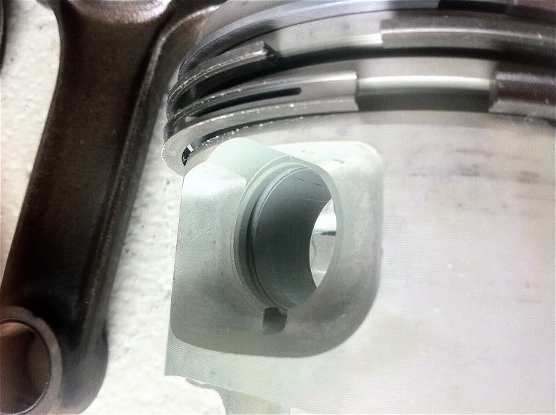
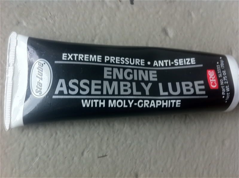
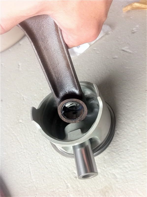
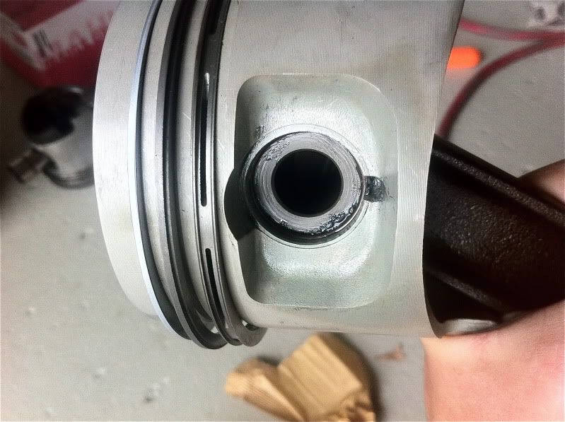
Once you get the first circlip in you need to grease the piston and gudgeon pin with pre assembly lube.
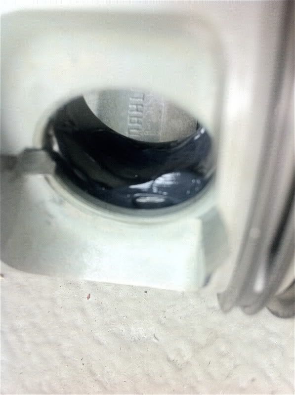
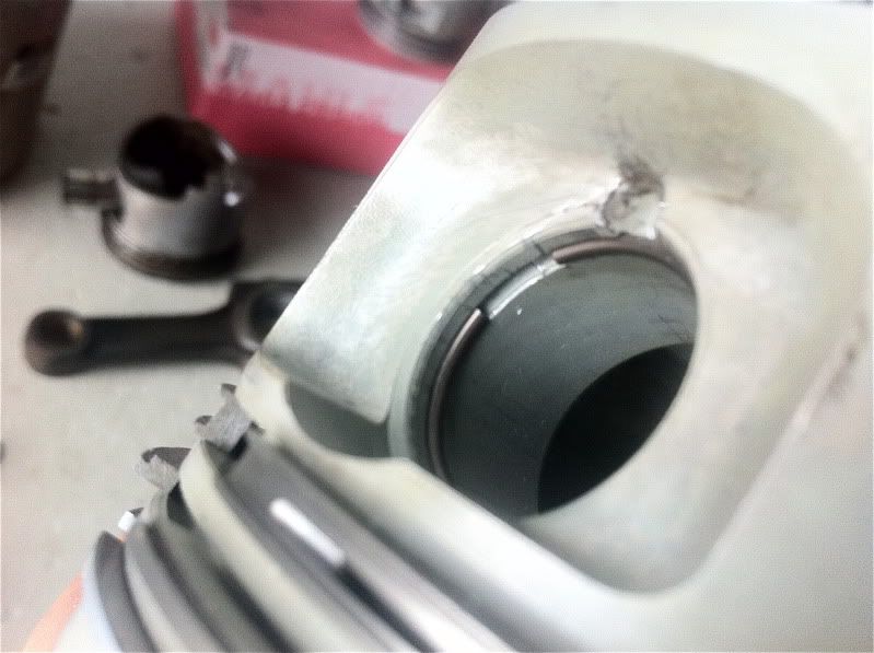
Now its time to mate the rod to the new piston, start by sliding the gudgeon pin through a little then dropping in the rod and then sliding it all home.. You need to slide it all the way to the end where the first circlip installed earlier acts as a stopper.
Now add the second of the two circlips and you now have a completed piston rod combo. 5 more to go.
Now this is over its time ti turn your attention to the crank.
being clean is vital, everything must be as clean as possible and since we have already cleaned our block we just have to make sure the crank is spotless too, Oak it in a tub of petrol, kerosene or turpentine and clean it with rags and a blower.
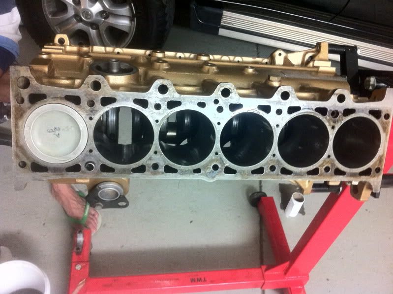
Turn the block over on the stand and it should look like this.
Now we need to add the bearings. They only go in one way but be careful not to bend them.
Some more pre assembly lube on the bearing faces.
Time to drop in the crank, be very careful as even though they are heavy and steal they are fragile and if dropped they will break, Its best to use two people.
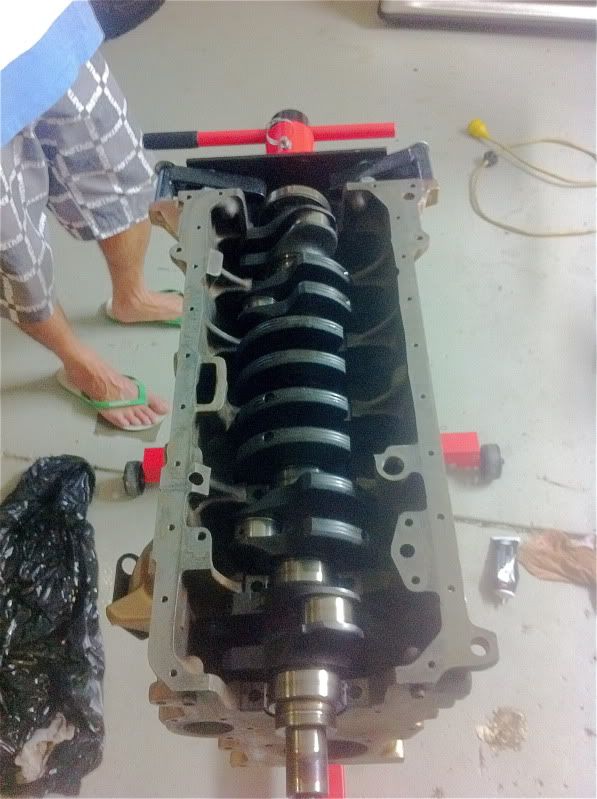
Some pre assembly lube on the crank.
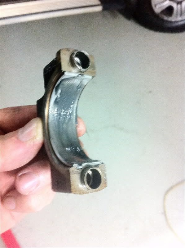
And put the main bearing caps on with the other side of the crank bearing.
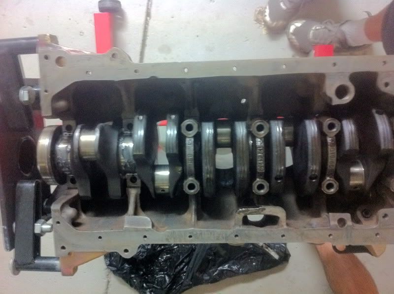
When them down be sure to use some anti seize on the threads. I dont torque them up only nip them up.
Once there all on and nipped up rotate the crank so number one cylinder is at TDC so the crank is pointing up in number one cylinder.
Prepare the piston and rod with some pre assembly lube on your new rod bearings. Put your ring compressor around the piston, Im told to keep the ring gaps away from the thrust face. Try and line the ring gaps up with the gudgeon pins.
And Nock your first piston home.
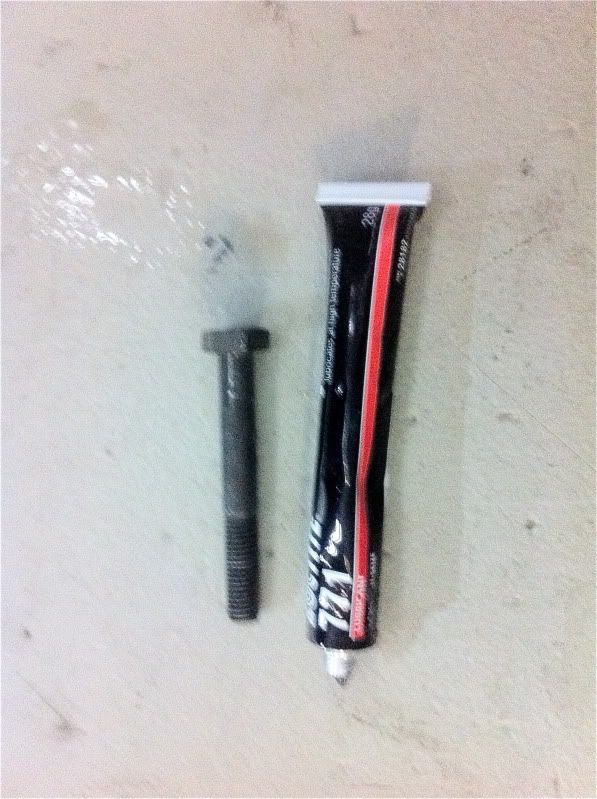
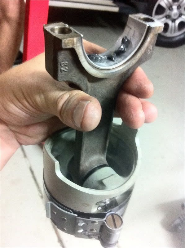
Some pre assembly lube on the rod cap, Be sure to put the cap on the right way around. (this is where your markings come in handy)
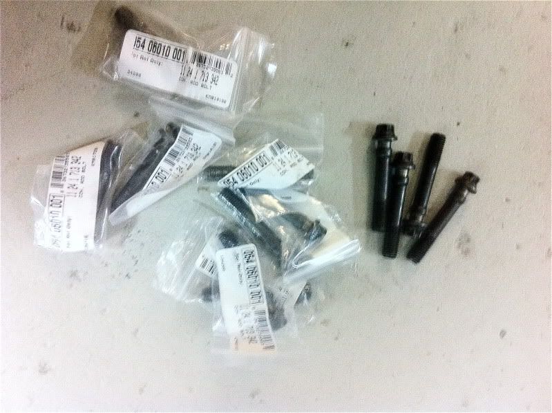
Bolt your rod cap down with new rod bolts.. They are stretch type soe they need replaing every single time they are removed (one time use) Use some anti seize on the bolt threads and just nip them up for now.
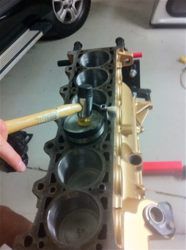
Rotate your crank so its pointing up in cylinder number two. and then repeat the process through all six pistons
Nocking the piston through the bore with the ring compressor using a rubber mallet.
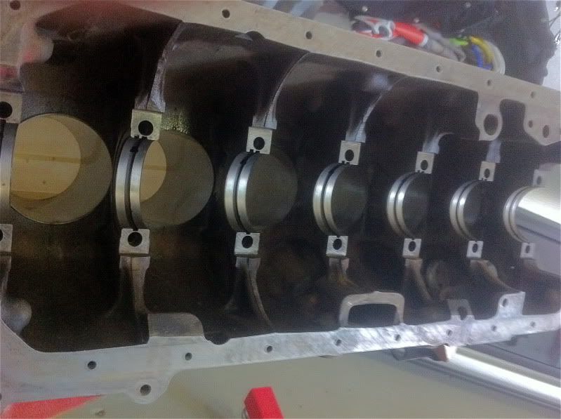
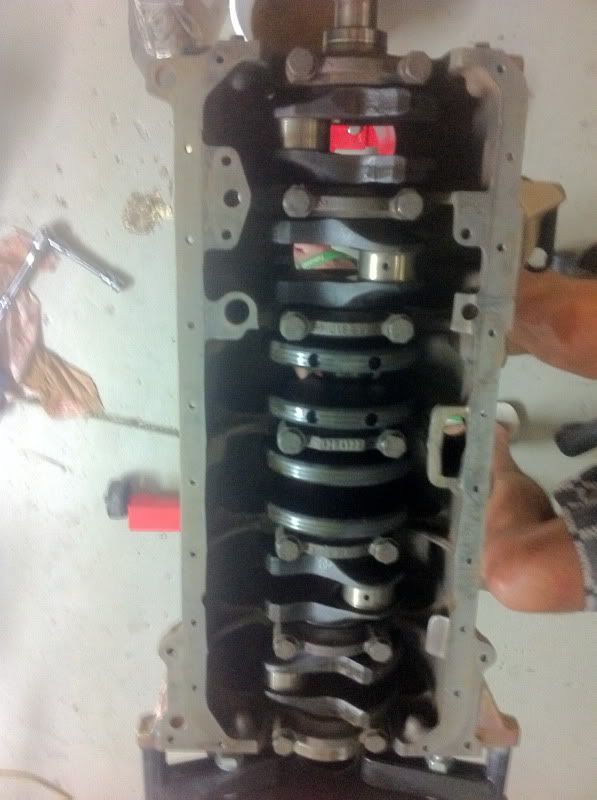
Once we have all six pistons and rods home its time to do it all up tight.
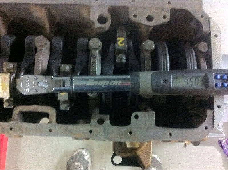
The crank bearing cap bolts get done up to 45ft-pnds starting from the middle and working your way to the ends.
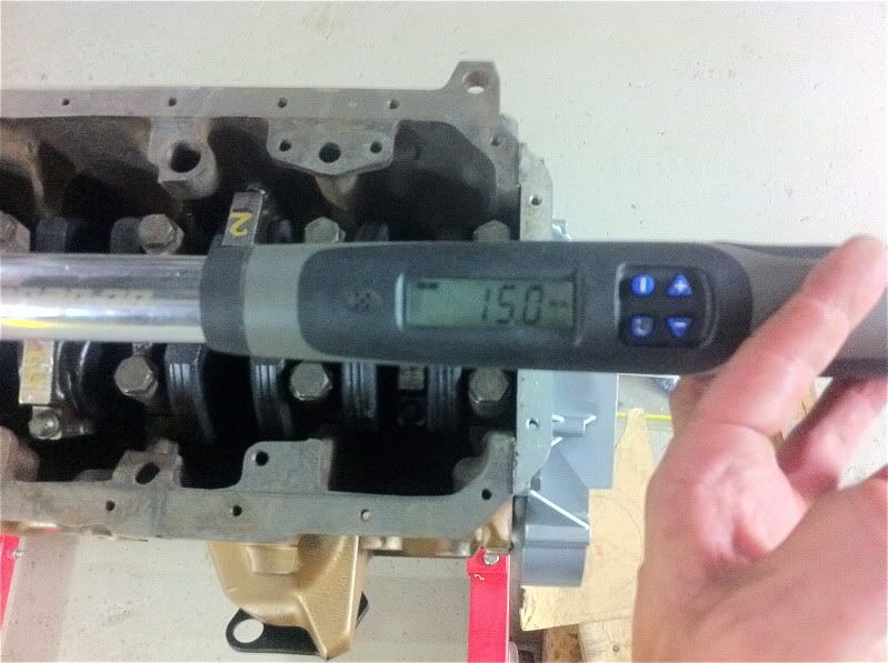
The rod bearing cap bolts all get done up to 15ft-pnds starting in the middle and working your way to the ends.
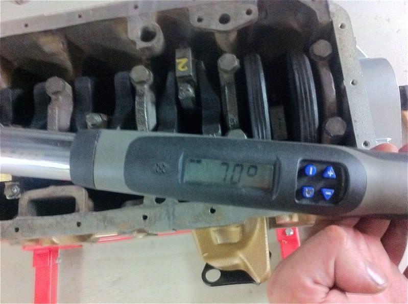
The the rod bearing cap bolts get done up a additional 70 degrees starting in the middle working your way to the ends.
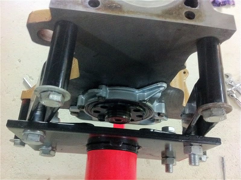
Now add the oil pump and do that up to 16ft-pnds
Once its all done up to specs its time to turn it over and rotate the whole thing.. Its should all spin pretty easy with a little bit of effort... (that is is you ordered the correct size bearings)
@@@@@@@@@@@@@@
Now that thats all done its time to prepare the front and rear engine plates. The rear one carries the rear main seal and the front one doubles as the timing case, it also carries two oil seals one for the crank and the other for the oil drive.
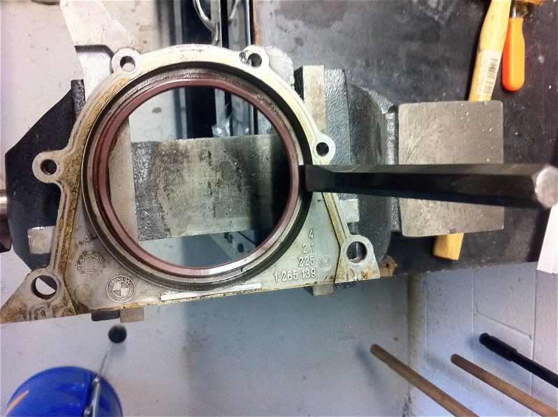
First thing to do is nock out the seal in the rear engine plate, use a blunt chisel and work your way around being very carful not to damage the plate. If you damage it you might end up with a oil leak so take your time... If you have a big socket or pipe you can press it our which is the best method.. ( I didnt have anything that big)
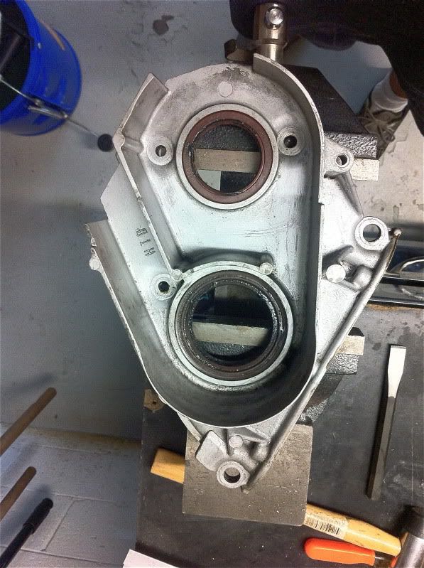
Same goes for the front timing case, For this one I used a socket on the smaller seal and part of the engine pulley to press it out in the vice.
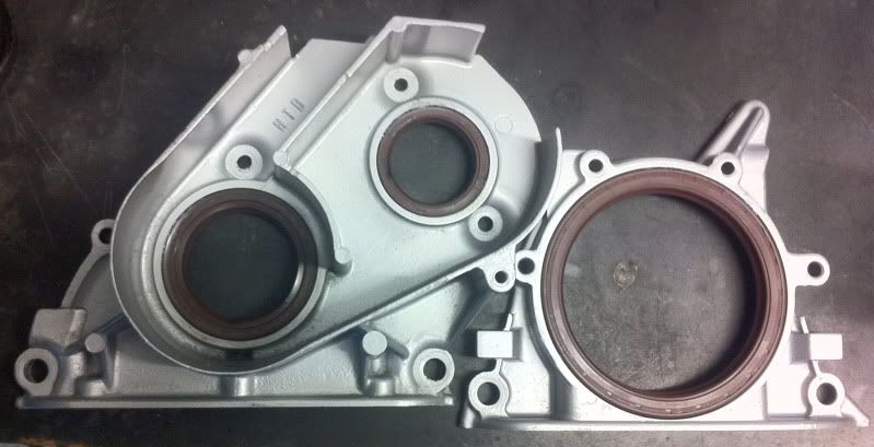
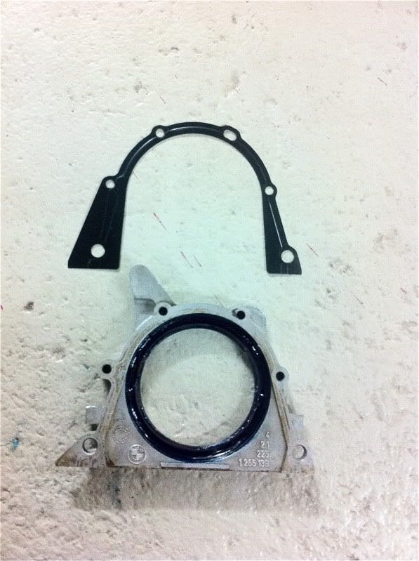
Both plates with their new seals with a fresh coat of paint ready to be re installed.
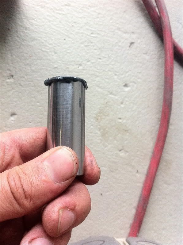
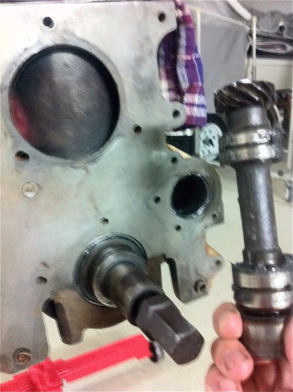
Next thing to do is slide the oil pump shaft in its home with some pre assembly lube.
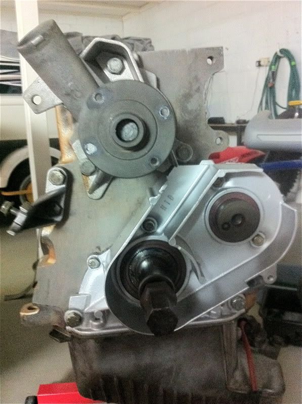
And then install the timing case on the front of the engine with a brand new gasket, be carful not to snare the oil seals as if they get damages you will have leaks.. I pack everything up with grease to make it easier. While your at it put the water pump on with its gasket.
Then the rear plate with its unique little metal gasket.
Bolt them all down with the 10 and 13 mm bolts, The 10mm ones get torqued to 11 ft-pnds and the 13 mm ones get torqued to 16ft-pnds
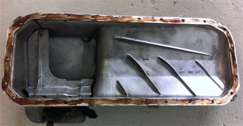
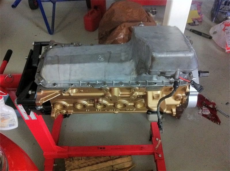
Now its time to prep the sump, I use a gasket sealant aswel as the gasket... I find the sealant holds the gasket when lining everything up and makes life a little easier, its also meant to fill in the finest of imperfections between the gasket and sump meaning no chance of leeks.
Bolt it all up using the 10mm bolts to 11ft-pnds.
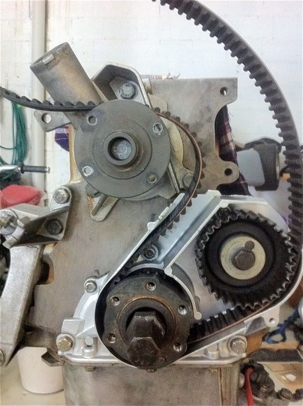
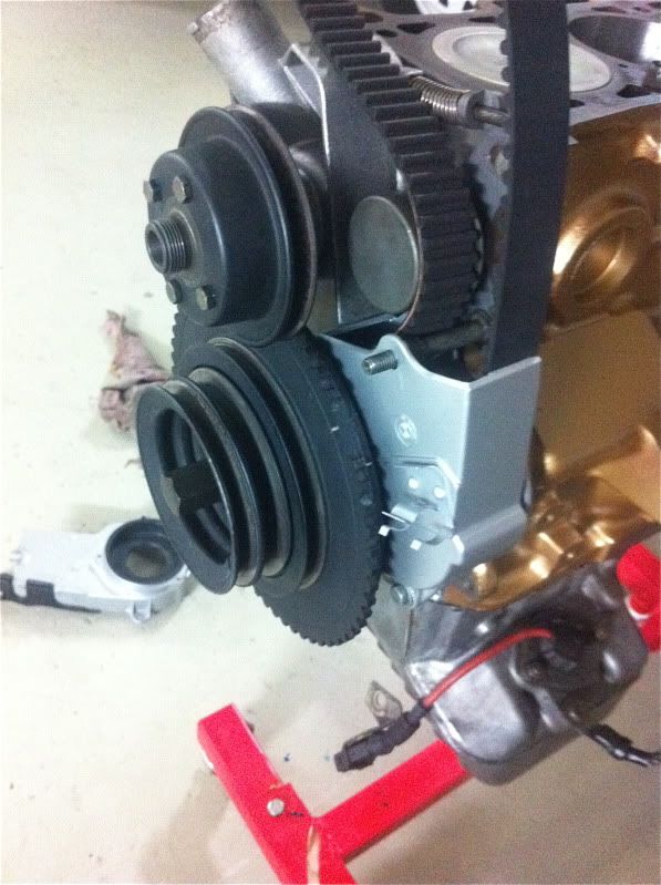
Now add the small crank pulley sliding it over the key way in the crank Also the oil pump pulley and timing belt.
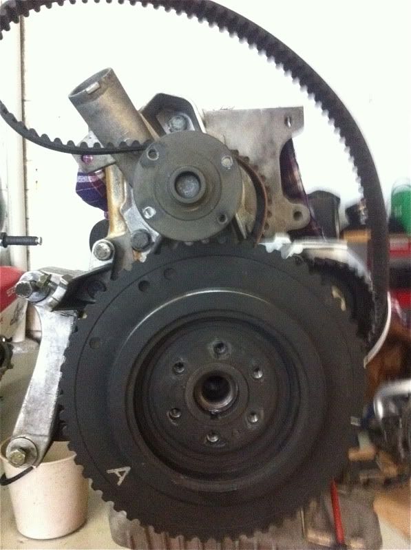
Now add the toothed timing wheel.
And now its time for the water pump, alternator, power steering and A/C pulleys.
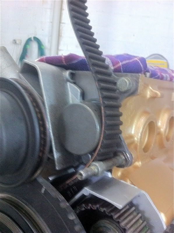
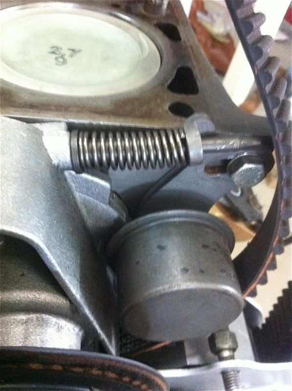
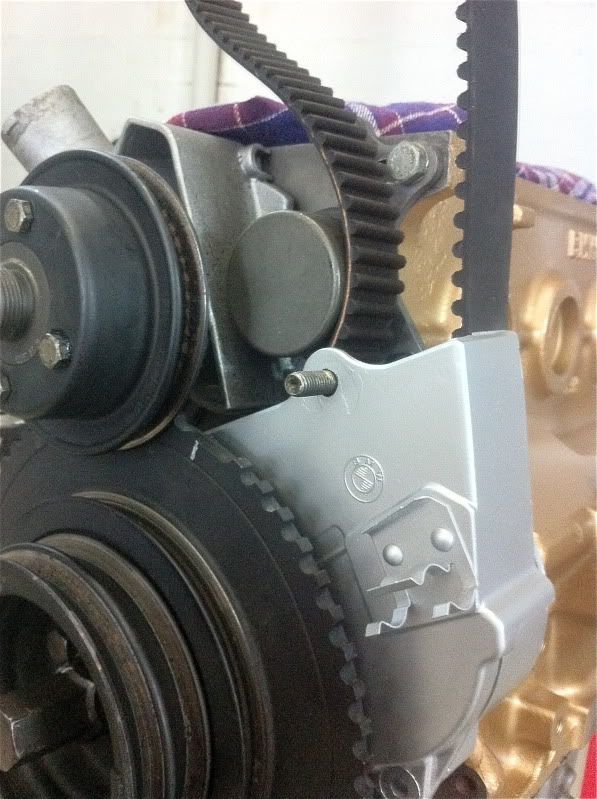
Now bolt your new tensioner in place with its new spring,
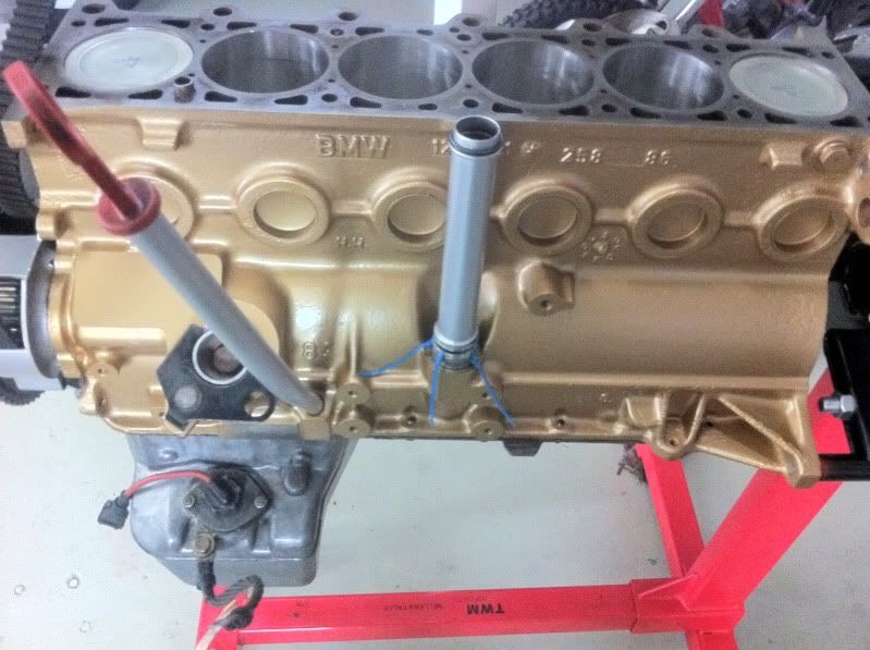
Might wanna add the dipstick and breather tube.
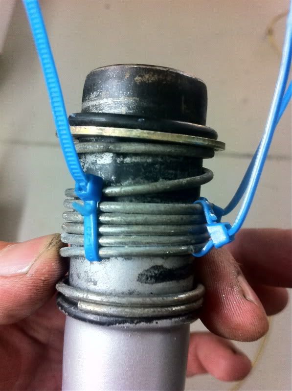
When adding the breather tube be sure to give it two new O rings and cable tie the spring down.
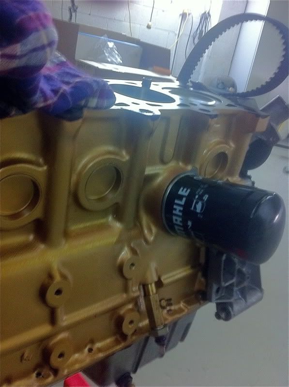
Might aswell bolt on the oil filter and oil pressure switch. In this motor I have added a T piece for a oil pressure gauge.
The bottom timing covers turn.
And now its ready to time up the bottom end ready for the head.
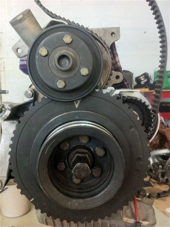
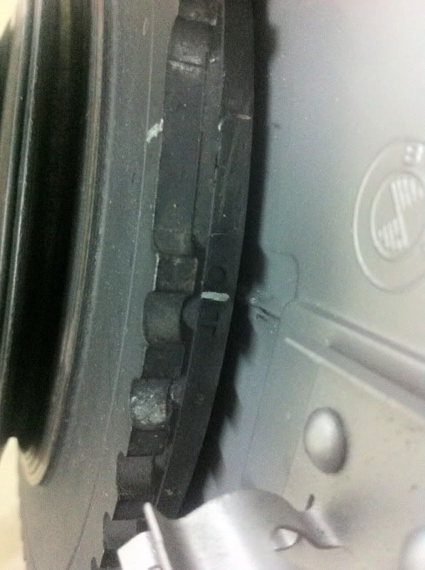
The toothed timing wheel has a marker on it, and its indicated with the marking O l T, I have highlighted it with white marker. The white line must line up with a marking on the timing cover.
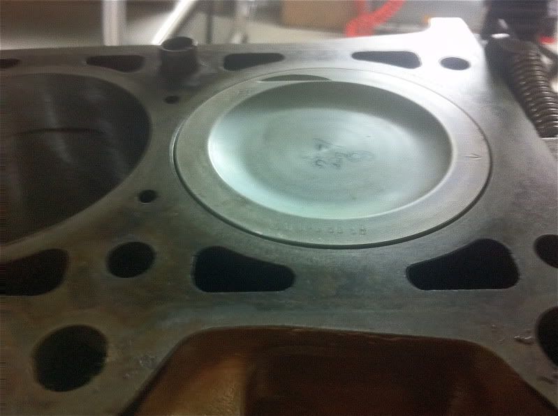
You will know when its right as piston one and six will be right up the top of their bores.
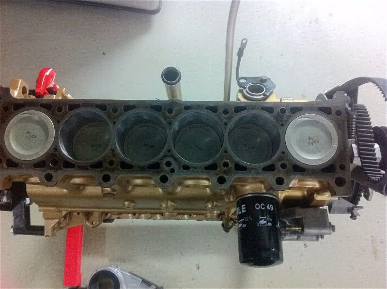
As this is a high comp engine the pistons protrude just a little out of the bores. This will be taken up by the head gasket.
And thats your bottom end done and complete, top end to come.
Aim is to show people it isn't that daunting and actually quite easy...
Enjoy
Building a m20 6 cylinder engine...
First thing to do is strip the engine down to its pants leaving just the engine block. Be sure to number the rods and pistons and place a little marker on them showing what direction the where removed from the block. It is absolutely critical that reassembly is the exact revers of how they were removed. You must mark the pistons the rods and the bearing caps, I put numbers and arrows with a paint marker so there can be no confusion.
Send the block away to your machinist and have them clean, hone and reface it.
It should come back looking something like this.
Honing.
Refaced.
The next thing you want to do is thoroughly clean it, even though you had the machinist clean it I promise you it will be filthy dirty. You need to use
petrol, kerosene or turpentine. I used all three in that order and then finished with some prepsol/ wax and grease remover. You need to use a air compressor and flush out all the oil ways to ensure there is no swarf or blockages as this will kill your new engine in seconds.
When you think its clean go over it again with tissue paper and when the tissue paper comes back clean with no grease or dirt you are ready to assemble.
This is typically how it will be strait from the machine shop.
Time for a fresh coat of paint.
Now if you are using your old piston and rod combo you can skip tis step.
Six brand new mahle pistons.
First thing to do is remove the old pistons off the rods... Be sure to do it in order as it is very very important that the rods go back in the block the same order the where removed.
Removing the cirlcip.
Nock the gudgeon pin through the piston using a suitable drift, be carefull not to damage anything... It makes it easier if you soak it in hot water first to let the metals expand a little.
Ready to reassemble with new piston gudgeon pin and circlips.
The cirlcip goes in this little groove with the greatest of care and frustration, expect a few nicks off your fingers and circlips flying in all directions.
Once you get the first circlip in you need to grease the piston and gudgeon pin with pre assembly lube.
Now its time to mate the rod to the new piston, start by sliding the gudgeon pin through a little then dropping in the rod and then sliding it all home.. You need to slide it all the way to the end where the first circlip installed earlier acts as a stopper.
Now add the second of the two circlips and you now have a completed piston rod combo. 5 more to go.
Now this is over its time ti turn your attention to the crank.
being clean is vital, everything must be as clean as possible and since we have already cleaned our block we just have to make sure the crank is spotless too, Oak it in a tub of petrol, kerosene or turpentine and clean it with rags and a blower.
Turn the block over on the stand and it should look like this.
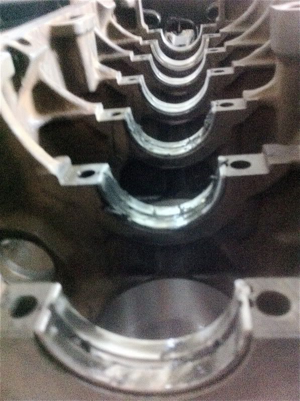
Now we need to add the bearings. They only go in one way but be careful not to bend them.
Some more pre assembly lube on the bearing faces.
Time to drop in the crank, be very careful as even though they are heavy and steal they are fragile and if dropped they will break, Its best to use two people.
Some pre assembly lube on the crank.
And put the main bearing caps on with the other side of the crank bearing.
When them down be sure to use some anti seize on the threads. I dont torque them up only nip them up.
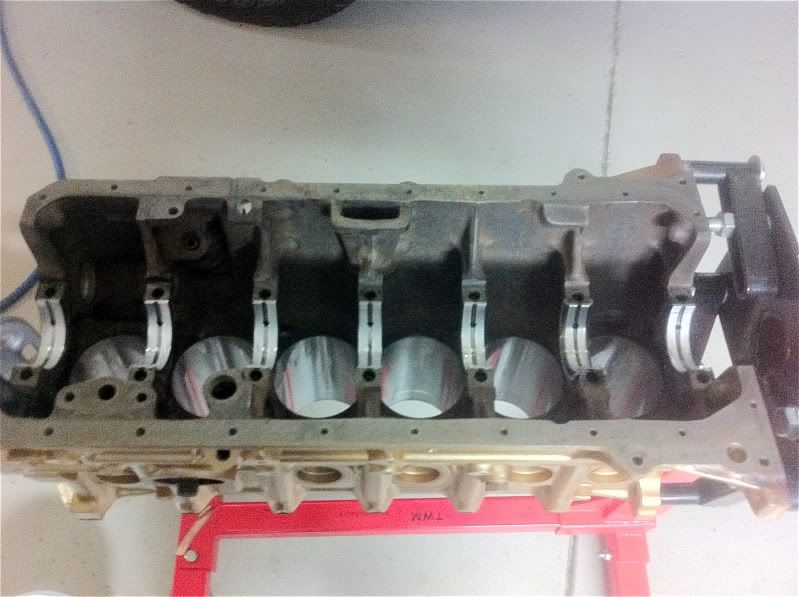
Once there all on and nipped up rotate the crank so number one cylinder is at TDC so the crank is pointing up in number one cylinder.
Prepare the piston and rod with some pre assembly lube on your new rod bearings. Put your ring compressor around the piston, Im told to keep the ring gaps away from the thrust face. Try and line the ring gaps up with the gudgeon pins.
And Nock your first piston home.
Some pre assembly lube on the rod cap, Be sure to put the cap on the right way around. (this is where your markings come in handy)
Bolt your rod cap down with new rod bolts.. They are stretch type soe they need replaing every single time they are removed (one time use) Use some anti seize on the bolt threads and just nip them up for now.
Rotate your crank so its pointing up in cylinder number two. and then repeat the process through all six pistons
Nocking the piston through the bore with the ring compressor using a rubber mallet.
Once we have all six pistons and rods home its time to do it all up tight.
The crank bearing cap bolts get done up to 45ft-pnds starting from the middle and working your way to the ends.
The rod bearing cap bolts all get done up to 15ft-pnds starting in the middle and working your way to the ends.
The the rod bearing cap bolts get done up a additional 70 degrees starting in the middle working your way to the ends.
Now add the oil pump and do that up to 16ft-pnds
Once its all done up to specs its time to turn it over and rotate the whole thing.. Its should all spin pretty easy with a little bit of effort... (that is is you ordered the correct size bearings)
@@@@@@@@@@@@@@
Now that thats all done its time to prepare the front and rear engine plates. The rear one carries the rear main seal and the front one doubles as the timing case, it also carries two oil seals one for the crank and the other for the oil drive.
First thing to do is nock out the seal in the rear engine plate, use a blunt chisel and work your way around being very carful not to damage the plate. If you damage it you might end up with a oil leak so take your time... If you have a big socket or pipe you can press it our which is the best method.. ( I didnt have anything that big)
Same goes for the front timing case, For this one I used a socket on the smaller seal and part of the engine pulley to press it out in the vice.
Both plates with their new seals with a fresh coat of paint ready to be re installed.
Next thing to do is slide the oil pump shaft in its home with some pre assembly lube.
And then install the timing case on the front of the engine with a brand new gasket, be carful not to snare the oil seals as if they get damages you will have leaks.. I pack everything up with grease to make it easier. While your at it put the water pump on with its gasket.
Then the rear plate with its unique little metal gasket.
Bolt them all down with the 10 and 13 mm bolts, The 10mm ones get torqued to 11 ft-pnds and the 13 mm ones get torqued to 16ft-pnds
Now its time to prep the sump, I use a gasket sealant aswel as the gasket... I find the sealant holds the gasket when lining everything up and makes life a little easier, its also meant to fill in the finest of imperfections between the gasket and sump meaning no chance of leeks.
Bolt it all up using the 10mm bolts to 11ft-pnds.
Now add the small crank pulley sliding it over the key way in the crank Also the oil pump pulley and timing belt.
Now add the toothed timing wheel.
And now its time for the water pump, alternator, power steering and A/C pulleys.
Now bolt your new tensioner in place with its new spring,
Might wanna add the dipstick and breather tube.
When adding the breather tube be sure to give it two new O rings and cable tie the spring down.
Might aswell bolt on the oil filter and oil pressure switch. In this motor I have added a T piece for a oil pressure gauge.
The bottom timing covers turn.
And now its ready to time up the bottom end ready for the head.
The toothed timing wheel has a marker on it, and its indicated with the marking O l T, I have highlighted it with white marker. The white line must line up with a marking on the timing cover.
You will know when its right as piston one and six will be right up the top of their bores.
As this is a high comp engine the pistons protrude just a little out of the bores. This will be taken up by the head gasket.
And thats your bottom end done and complete, top end to come.