Megasquirting Your M20
This Page Is a work in Progress by Gruelius. I am not responsible for any incorrect information (feel free to update it).
I recently completed a megasquirt fuel + spark conversion on my Ljet m20b23. I first converted it to motronic and then set it up for wasted spark. This guide will be a general guide, i will also add specifics for series 1 e30 owners and ljet e30 owners. While i will list possible options this guide will be tailored for Motronic 1.3 single coil and wasted spark setups.
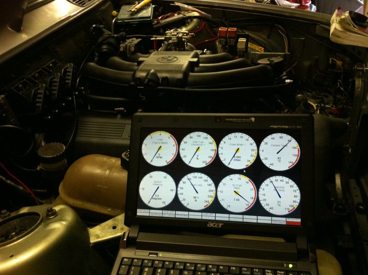
Ignore the buggered AFR IAT and CLT values, they werent connected :P
Contents
Possible Combinations
Fuel Only (Possible on Ljet cars without any modification as dizzy handles ignition, works with ANY MS ecu).
Fuel + Single coil spark (Requires Full Motronic 1.3 conversion for Ljet/Motronic cars).
Fuel + Wasted spark (requires motronic 1.3 harness and triggerwheel on ljet cars).
Motronic 1.3 to Megasquirt
Parts Required
MS II ecu (While MS1 can run ignition with megasquirt Extra this guide is for ms2 extra).
MS2 Extra firmware.
M50 TPS and adapter (while not required, very helpful for tuning).
LC-1 wideband (i would consider essential but a narrowband could be used, would need a external wideband for tuning).
idle driver board.
Wasted Spark
coil driver board (before purchasing another board please read the wasted spark section).
Making the adapter
I wont go into too much detail here as it has been covered many times by many people. It can be installed into the case or outside the case, i prefer to just create a harness adapter and have the ecu seperate as i am not too good with fiddly stuff. If doing wasted spark do not use the SPARKA output of the megasquirt ecu.
This is a photo of how i made my adapter (showing coil boards too)

From [1] run by chris325ix
(While that guide is correct, I would and did wire the cps ground to #2, the megamanual hints towards it being a seperate ground in future revisions of MS)

DIYEFI also show how it can be installed very well inside the case. I would recommend chris325ix's wiring table over their pinout http://wiki.diyefi.co.uk/Converting_a_Motronic_ECU_Box_to_Megasquirt
You will also need to trigger the main relay to turn on (the Motronic 1.3 ecu has a constant 12v feed for a battery backup and turns on the main relay when it recieves the ignition signal).
Main Relay Triggering
There are two ways to do it (Both listed here [2]), wire up a transistor based circuit or just modify the relay wiring. I have tried both and had NO luck with the transistor setup. People have gotten it to work but after a week of messing about i tried the modified relay holder method and it worked fine.
Idle Control Valve
In order to use the factory 3 wire idle control valve you need an adapter board. I decided to purchase the glensgarage board as it was well documented and the premade pcb was top quality including all required fasteners. Can be purchased here [3].
Board website is here http://www.glensgarage.com/3wire/
For the required settings please refer to the Setting section
Wasted Spark
With Wasted spark you will be using non factory coils. There are two types of coils, ones with logic boards allready inside them and ones that require ignitors. The coilpack i decided to use was a GM V6 coilpack which are quite cheap and readily available at australian yards.
For wasted spark all that is needed is the extra coil drivers and wiring to them. while it is possible to just use the default sparkA output and the 2 spare outputs of the glensgarage idle board, I ended up using a seperate coil driver board. This was because the ECU i got from DIYautotune by default does not have a transistor installed for the sparkA output.
The wiring is dependant on the MS ecu you are using. A great guide is provided by DIYautotune here [4].
| Output | V2.2 Input | V3 Input | V3.57 Input |
| Spark A | Right of R25 | Top of R26 | U1 pin 7 |
| Spark B | Right of R28 | Top of R29 | U1 pin 8 |
| Spark C | Right of R26 | Top of R27 | U1 pin 9 |
Especially for the 3.57 boards i recommend the wiring from the ecu to the coil drivers not be done through the DB37 connector as it would require further messing about inside the ecu.
Using the GM V6 Coilpack the internal electronics are to be gutted as we will just be using it for its coils and the coil holder

As for leads i just grabbed a bunch of premade lengths from the bosch stand at my local cheap autostore.
Oxygen Sensor
The LC1 can be wired into the stock harness. I did not take pictures but i just cut the connector off a bosch narrowband and used that. The example i had had four wires, to whites a grey and a black.
The wiring i was told was Grey = Earth, Black = signal, White = Power. I cannot confirm this yet as the ecu has not been run with this lc1 setup yet.
Settings
This is best done by looking at the website [www.megamanual.com] and other popular tunes. It is quite simple, just make sure when doing wasted spark you have the right outputs selected. For the trigger wheel the settings are 60 teeth 2 missing and use 84 degrees as your tooth #1 angle.
