Stripping and Rebuilding an M20 Cylinder Head
In this guide, we will show you the correct procedure for stripping and rebuilding an M20 Cylinder Head. This includes 2.0, 2.3, 2.5 litre engines. For the benefit of the guide, we will be using an M20 2.5 head.
- Required Tools
- Female Torx Socket
- Old Timing Belt.
- Lockable Grips
- 8mm Spanner
- 10mm Spanner
- 3mm Allen Key
- 11mm Deep 1/4" Drive Socket
- Short 1/4" Drive Extension Bar
- Feeler Gauges
- Valve Spring Compressor
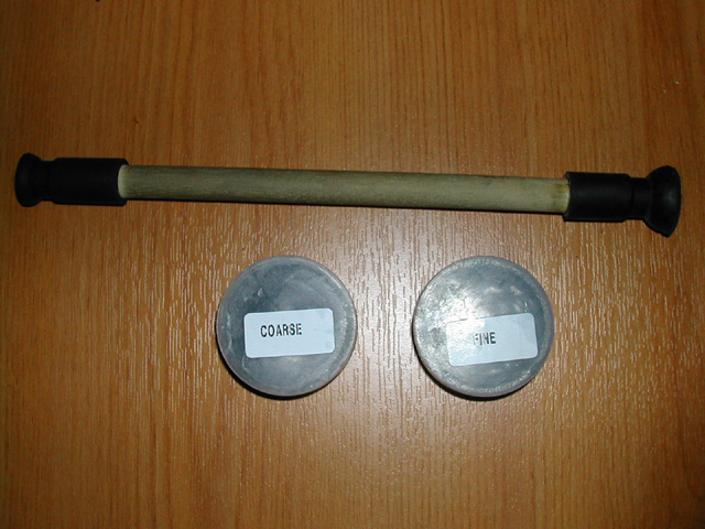
- Valve Grinding Stick & Paste
- Suitable drift (1/2" Drive Extension)
- Hammer
- Magnetic Ended Screw Driver
- Spark Plug Wrench
Stripping
Before doing anything else, it's preferable to place the head on a workmate or similar work bench with a gap in the middle because as you turn the valve train over, the valves will hit if you have it on a flat surface. Now remove the spark plugs with a suitable plug wrench.
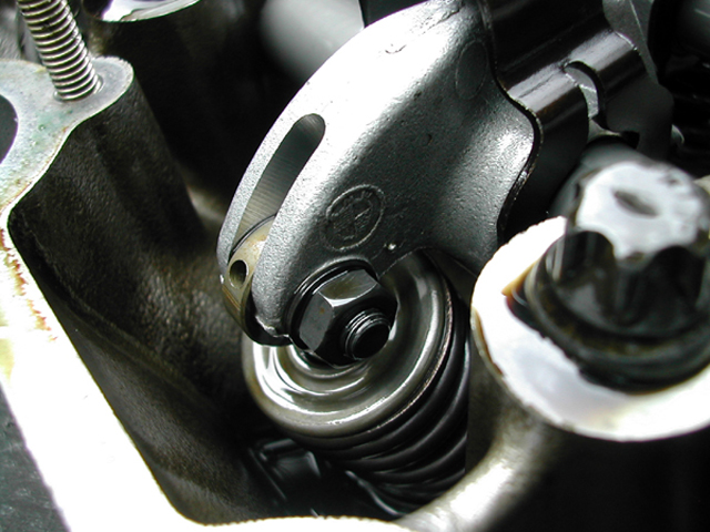
The first thing to do is slacken off all the valve eccentrics. Use a 10mm spanner and loosen the nut on each rocker pictured below.
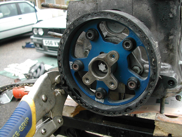
Once you've slackened off the eccentrics, we need to remove the top pulley so that we can remove the rocker shafts. This is done by securing the pulley with an old timing belt and a pair of lockable pliers, you will now be able to remove the torx bolt holding the pulley in place.
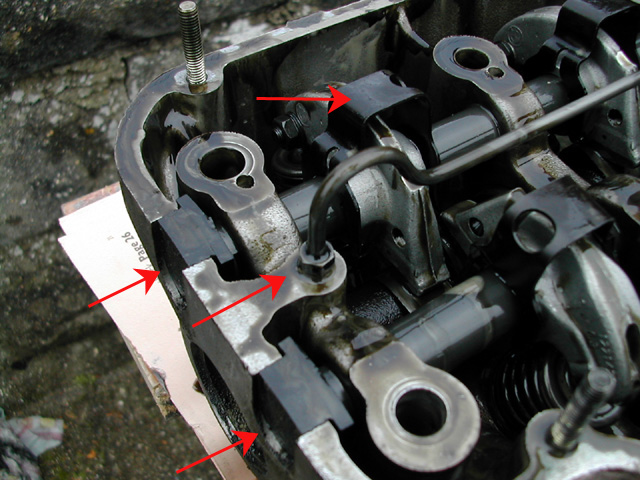
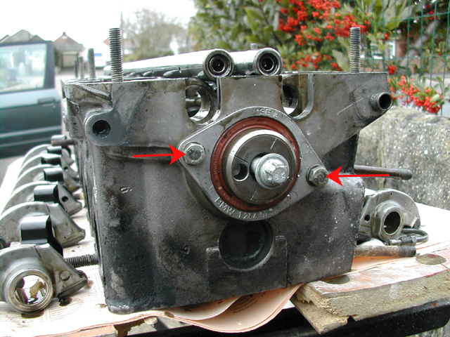
Once the front pulley has been removed, unclip all 12 rocker retaining clips. These can be eased off with a screw driver of pulled off by hand. Also remove the rocker shaft end seals (4) and the oil spray bar which is attached with 2 x 8mm nuts. All parts to be removed are arrowed on the image below.
The next part of the procedure is to remove the rockers and shafts. I usually work with the pulley end of the head to my right. Concentrate on removing one rocker shaft at a time. We will be removing the exhaust side rocker shaft to begin with. Place the pulley bolt back into the end of the camshaft so that you turn the camshaft. Keep turning the bolt until it fully tightens.
Before removing the rocker shafts, give them a careful going over to check for any nicks, gouges or scratches that might damage the shaft bores as they are removed from the head.
IMPORTANT NOTE: Remember that you will only be able to turn the camshaft in a clockwise direction from now on. Attempts to turn in a counter clockwise direction will just remove the torx bolt.
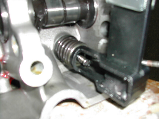
Rotate the camshaft until exhaust rocker number 6 is under full load. You can tell this because the camshaft lobe will be pointing upwards and you will be able to feel the other rockers will not be under tension because they will move back and forth slightly. Please see the diagram which shows a cross section view of how exhaust rocker number 6 should look at this time. For reference, cylinder number 1 is the cylinder nearest the top pulley end of the head and number 6 is the opposite end.
Next remove the rocker shaft retaining plate, this should come free with some gentle persuasion using a flat bladed screw driver.
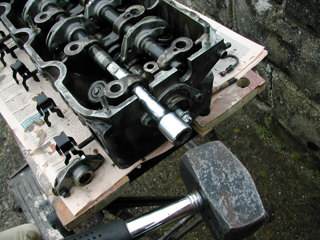
Take a suitable drift, I found that a 1/2" drive extension bar was the perfect size. Use a hammer to knock the exhaust rocker shaft out from the right hand side of the cylinder head. You only need to knock it a short distance, just enough so that you can slide the number 1 exhaust rocker from it's shaft.
Once the first rocker is removed, you will need to turn the camshaft so that the exhaust lobe for rocker number 1 is in the same position as before. It will not be pushing on a rocker as before because you have removed this rocker. Before turning the camshaft, ensure that the rockers are all centred over their respective camshaft lobes because they can easily be moved when you drift the rocker shaft out. When the camshaft for exhaust rocker number 1 is at full lift, you will find that the remaining rockers on the exhaust side will be under no tension. You should now be able to pull the rocker shaft out using your hands. Remember to keep the rockers in the correct order in which they were removed. It's a good idea to mark them with a permanent pen.
Repeat the above procedure for the inlet rocker shaft and remove this also, you should now be left with the camshaft and valves left in place for removal.
NOTE: You can now place the cylinder head on a flat surface if you wish because all valves will now be closed.
Now that the rockers and shafts have been removed, we can take the camshaft out. Remove the 2 x 10mm bolts holding the end plate in place then carefully prise the plate free with a flat bladed screw driver. Once the plate has been removed, the camshaft will slide out.
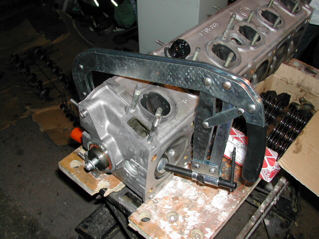
The final thing to do is to remove the valves. These are held in place with a spring assembly which needs to be compressed using a Valve Spring Compressor in order for them to be removed. Turn the cylinder head on it's side and then compress the valve spring with the compressor. When you have compressed the valve spring you will be able to use a magnetic screw driver to remove the valve retaining collets from the end of the valve stem.
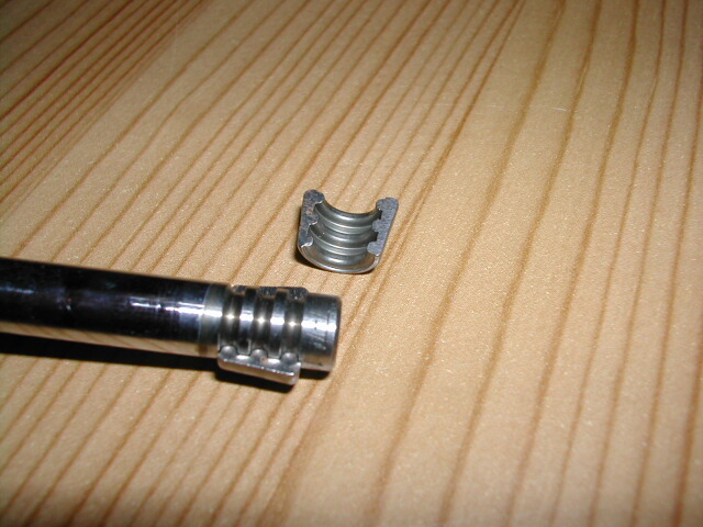
You can see from the below picture how the collets clasp around the end of the valve stem.
Once you have removed the collets, slacken off the valve spring compressor and remove the springs. The valve should now slide out from the underside of the head.
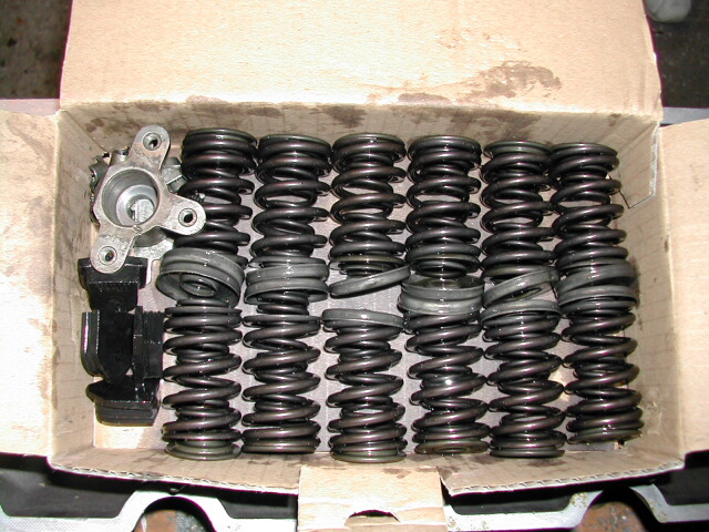
Once again, it's important to mark the valves and keep the springs in order so that they can be replaced in the same order in which they were removed. Repeat this procedure for each valve in turn and then keep all springs and components in a box or a safe place.
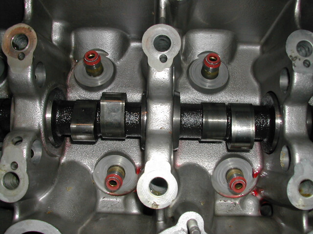
The final part of stripping the cylinder head is to remove the old valve stem oil seals. These are the red coloured seals in the picture below and can be easily removed with a pair of long-nosed pliers. Once these are removed you will be left with a bare cylinder head casting.
Rebuilding
Preparing the Cylinder Head for Re-Assembly
Before you actually rebuild the head, it's a good idea to carry out a few routine checks and maintenance to check that the head is in good order.
Firstly take the cylinder head to a machine shop and request that they check the tolerances of the valve guides (take your valves with you), check the face of the head for warps, have it pressure tested for cracks. If all is okay then request for it to be "chemically dipped" and "refaced". A chemical dip removes all carbon deposits an generally cleans the head up to a new finish again. You'll probably notice that your current cylinder head is stained brown. A reface is where a very thin surface is removed from the face of the cylinder head giving you a nice smooth finish ready for you to mount your gasket against.
When you get the head back from the machine shop you should re-grind the valve seats. If you look around the rim of the valve where it contacts the head when it opens and closes, you will notice that it's most probably very shiny which is bad for a good seal. Anyone can regrind valve faces but you will need a grinding kit which consists of grinding paste and a grinding stick. These can be bought very cheaply from any motor factors.
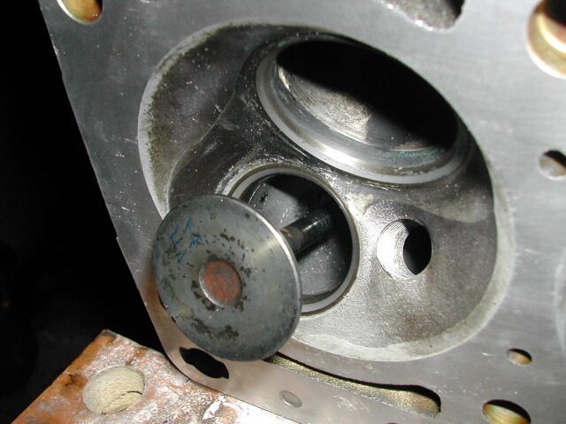
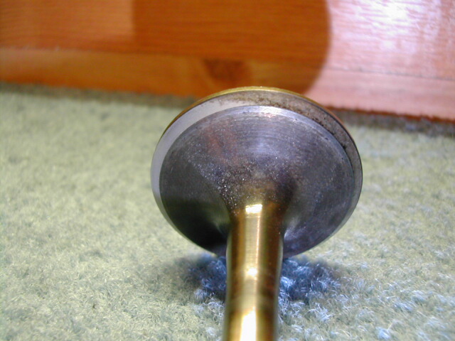
You can see from the below picture the difference between a valve which has been freshly re-ground and an untouched valve. Even new valves need grinding in to obtain the correct seal against the cylinder head. If you look at the below picture, you will see that the left hand side of this valve has a smooth dull grey finish, this is what the entire rim of the valve should look like after a re-grind. There should be no spots or shiny places.
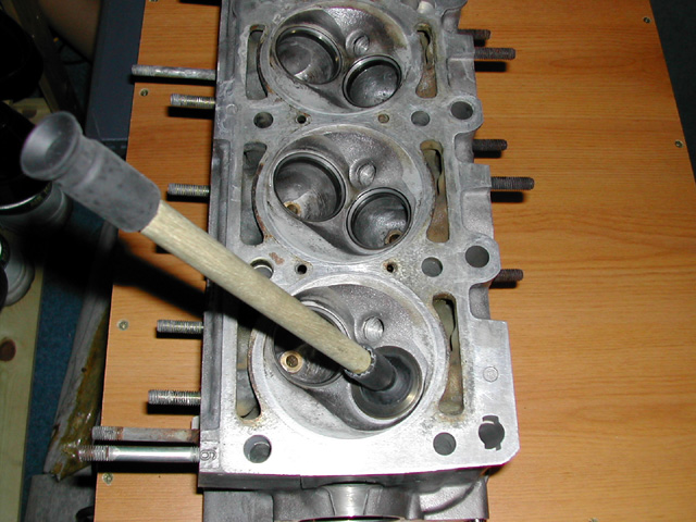
To regrind a valve, the procedure is actually very simple. Take a small dab of the fine grinding paste and cover the rim of the valve with it. Next place the valve in the correct port on the upturned cylinder head and stick the grinding stick to the valve. Now simply rub the stick back and forth between your hands to grind the two surfaces together. Keep checking and add more paste if necessary. Stop once you see both surfaces (the valve and the head) have a smooth dull grey finish. Repeat for all 12 valves.
NOTE: Ensure that all grinding paste is thoroughly cleaned away before re-assembly of the head.
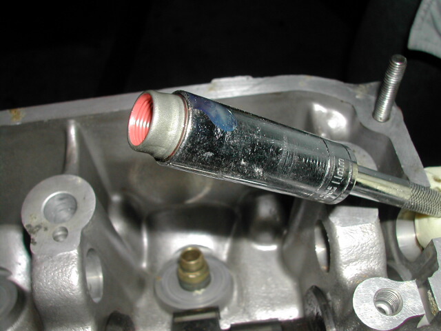
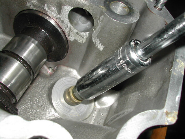
It's important to install new Valve Stem Oil Seals before replacing the valves. There is a special tool available for installing these seals but a deep 1/4" Drive 11mm socket fits perfectly. Begin by wetting the inside of the valve stem oil seal with some new oil to allow easier fitting. Place the seal on the end of the 11mm socket and then use a firm force to push the seal into place making sure that you keep the seal straight.
Reassembling the Cylinder Head
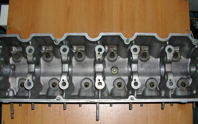
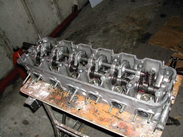
Reassembly of the cylinder head is very much the reverse procedure for stripping it. Begin by reinstalling all valves and springs in the correct order. The worst part is refitting the valve collets and getting them to stay in place and I've found that dipping them in some clean oil helps them stick to the valve stem. You can also re-install the camshaft at this point, smother all moving surfaces with Engine Assembly Lube and slide the camshaft back in place. It's a good idea to replace the camshaft end seal and o-ring as these are a common source of leaks and are easy to change while the head is off and in this state. At this stage, the head should look like this.
Now is a good time to check that the re-ground valves are sealing properly. Place the head on a bench and then tip a spoonful of fuel down each port in turn and check for any leaks underneath. If you've done it correctly the fuel will not leak through. If you have any which are leaking then it's advisable to remove and regrind again until you reach a satisfactory seal.
The next job is to replace the rockers and rocker shafts. We will start with the exhaust shaft first. Turn the cam until the lobe for exhaust rocker 6 is at full lift, you should now be able to slide the shaft back through (from the right hand side) slipping on the first five rockers as you go. Stop before you get to number six. Now make sure that all rockers are sitting over their respective cam lobes and turn the camshaft so that number one rocker is at full lift. Once again use a suitable drift to knock the shaft all the way in and slide on rocker number 6 at the same time.
Repeat this procedure with the inlet side rocker shaft and rockers. Make sure that when you install the rocker shafts, the notches for the retaining plate are lined up. Re-install the retaining plate, rocker retaining clips and rocker shaft end seals. Also replace the oil spray bar and refit the top pulley.
Now is an ideal time to adjust your valve clearances, please see the tech article for the procedure for doing this. It makes life much easier to do this while the head is off the car.
